2003 JEEP GRAND CHEROKEE Message system
[x] Cancel search: Message systemPage 1426 of 2199

(3) Apply a small amount of clean engine oil to
o-rings.
(4) Position filter/regulator to body and install 2
bolts. Tighten bolts to 3 N´m (30 in. lbs.) torque.
(5) Connect 3 fittings. Refer to Quick-Connect Fit-
tings.
(6) Connect negative battery cable to battery.
(7) Start engine and check for leaks.
FUEL LEVEL SENDING UNIT /
SENSOR
DESCRIPTION
The fuel gauge sending unit (fuel level sensor) is
attached to the side of the fuel pump module. The
sending unit consists of a float, an arm, and a vari-
able resistor track (card).
OPERATION
The fuel pump module has 4 different circuits
(wires). Two of these circuits are used for the fuel
gauge sending unit for fuel gauge operation, and for
certain OBD II emission requirements. The other 2
wires are used for electric fuel pump operation.
For Fuel Gauge Operation:A constant input
voltage source of about 12 volts (battery voltage) is
supplied to the resistor track on the fuel gauge send-
ing unit. This is fed directly from the Powertrain
Control Module (PCM).NOTE: For diagnostic pur-
poses, this 12V power source can only be veri-fied with the circuit opened (fuel pump module
electrical connector unplugged). With the con-
nectors plugged, output voltages will vary from
about 0.6 volts at FULL, to about 8.6 volts at
EMPTY (about 8.6 volts at EMPTY for Jeep
models, and about 7.0 volts at EMPTY for
Dodge Truck models).The resistor track is used to
vary the voltage (resistance) depending on fuel tank
float level. As fuel level increases, the float and arm
move up, which decreases voltage. As fuel level
decreases, the float and arm move down, which
increases voltage. The varied voltage signal is
returned back to the PCM through the sensor return
circuit.
Both of the electrical circuits between the fuel
gauge sending unit and the PCM are hard-wired (not
multi-plexed). After the voltage signal is sent from
the resistor track, and back to the PCM, the PCM
will interpret the resistance (voltage) data and send
a message across the multi-plex bus circuits to the
instrument panel cluster. Here it is translated into
the appropriate fuel gauge level reading. Refer to
Instrument Panel for additional information.
For OBD II Emission Monitor Requirements:
The PCM will monitor the voltage output sent from
the resistor track on the sending unit to indicate fuel
level. The purpose of this feature is to prevent the
OBD II system from recording/setting false misfire
and fuel system monitor diagnostic trouble codes.
The feature is activated if the fuel level in the tank
is less than approximately 15 percent of its rated
capacity. If equipped with a Leak Detection Pump
(EVAP system monitor), this feature will also be acti-
vated if the fuel level in the tank is more than
approximately 85 percent of its rated capacity.
DIAGNOSIS AND TESTING - FUEL LEVEL
SENDING UNIT
The fuel level sending unit contains a variable
resistor (track). As the float moves up or down, elec-
trical resistance will change. Refer to Instrument
Panel and Gauges for Fuel Gauge testing. To test the
gauge sending unit only, it must be removed from
vehicle. The unit is part of the fuel pump module.
Refer to Fuel Pump Module Removal/Installation for
procedures. Measure the resistance across the send-
ing unit terminals. With float in up position, resis-
tance should be 20 ohms (+/- 5%). With float in down
position, resistance should be 270 ohms (+/- 5%).
REMOVAL
The fuel gauge sending unit (fuel level sensor) and
float assembly is located on the side of fuel pump
module (Fig. 6). The fuel pump module is located
within the fuel tank.
Fig. 5 Fuel Filter/Fuel Pressure Regulator Removal/
Installation
1 - FUEL FILTER/FUEL PRESSURE REGULATOR
2 - MOUNTING BOLTS (2)
WJFUEL DELIVERY 14 - 7
FUEL FILTER/PRESSURE REGULATOR (Continued)
Page 1491 of 2199

KEY-IN IGNITION SWITCH
DESCRIPTION
The key-in ignition switch is concealed within and
integral to the ignition switch, which is mounted on
the steering column. The key-in ignition switch is
actuated by the ignition lock cylinder mechanism,
and is hard wired between a body ground and the
Body Control Module (BCM) through the instrument
panel wire harness.
The key-in ignition switch cannot be adjusted or
repaired and, if faulty or damaged, the entire igni-
tion switch unit must be replaced,(Refer to 19 -
STEERING/COLUMN/LOCK CYLINDER HOUSING
- REMOVAL). For complete circuit diagrams, refer to
Body Control Modulein the Contents of Wiring
Diagrams.
OPERATION
The key-in ignition switch closes a path to ground
for the BCM when the ignition key is inserted in the
ignition lock cylinder, and opens the ground path
when the key is removed from the ignition lock cyl-
inder. The BCM monitors the key-in ignition switch
status through an internal pull-up, then sends the
proper switch status messages to other electronic
modules over the Programmable Communications
Interface (PCI) data bus network. The key-in ignition
switch status is also used by the BCM as an input
for chime warning system operation.
DIAGNOSIS AND TESTING
KEY-IN IGNITION SWITCH
For complete circuit diagrams, refer toBody Con-
trol Modulein the Contents of Wiring Diagrams.
WARNING: ON VEHICLES EQUIPPED WITH AIR-
BAGS, REFER TO GROUP 8M - PASSIVE
RESTRAINT SYSTEMS BEFORE ATTEMPTING ANY
STEERING WHEEL, STEERING COLUMN, OR
INSTRUMENT PANEL COMPONENT DIAGNOSIS OR
SERVICE. FAILURE TO TAKE THE PROPER PRE-
CAUTIONS COULD RESULT IN ACCIDENTAL AIR-
BAG DEPLOYMENT AND POSSIBLE PERSONAL
INJURY.(1) Disconnect and isolate the battery negative
cable. Disconnect the instrument panel wire harness
connector from the key-in ignition switch connector
receptacle on the ignition switch. Check for continu-
ity between the key-in ignition switch sense and
ground terminals of the key-in ignition switch con-
nector receptacle. There should be continuity with
the key inserted in the ignition lock cylinder, and no
continuity with the key removed from the ignition
lock cylinder. If OK, go to Step 2. If not OK, replace
the faulty ignition switch unit.
(2) Check for continuity between the ground cir-
cuit cavity of the instrument panel wire harness con-
nector for the key-in ignition switch and a good
ground. There should be continuity. If OK, go to Step
3. If not OK, repair the open ground circuit to ground
as required.
(3) Disconnect the gray 26-way instrument panel
wire harness connector from the Body Control Mod-
ule (BCM) connector receptacle. Check for continuity
between the key-in ignition switch sense circuit cav-
ity of the instrument panel wire harness connector
for the key-in ignition switch and a good ground.
There should be no continuity. If OK, go to Step 4. If
not OK, repair the shorted key-in ignition switch
sense circuit as required.
(4) Check for continuity between the key-in igni-
tion switch sense circuit cavities of the instrument
panel wire harness connector for the key-in ignition
switch and the gray 26-way instrument panel wire
harness connector for the BCM. There should be con-
tinuity. If OK, use a DRB scan tool and the proper
Diagnostic Procedures manual to test the BCM. If
not OK, repair the open key-in ignition switch sense
circuit as required.
LOCK CYLINDER
REMOVAL
The ignition key must be in the key cylinder for
cylinder removal. The key cylinder must be removed
first before removing ignition switch.
(1) Disconnect negative battery cable at battery.
(2) If equipped with an automatic transmission,
place shifter in PARK position.
(3) Rotate key to ON position.
19 - 14 COLUMNWJ
Page 2095 of 2199
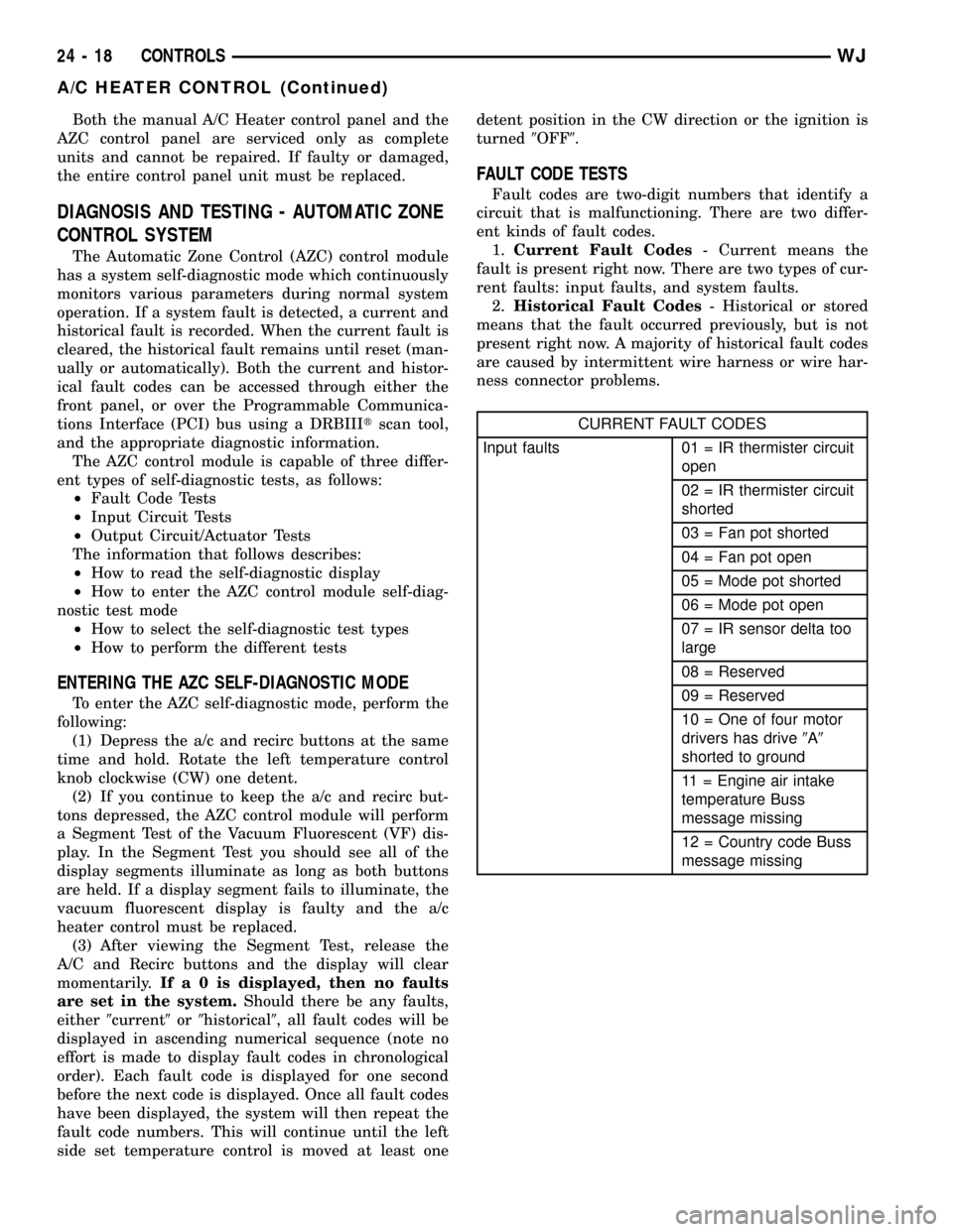
Both the manual A/C Heater control panel and the
AZC control panel are serviced only as complete
units and cannot be repaired. If faulty or damaged,
the entire control panel unit must be replaced.
DIAGNOSIS AND TESTING - AUTOMATIC ZONE
CONTROL SYSTEM
The Automatic Zone Control (AZC) control module
has a system self-diagnostic mode which continuously
monitors various parameters during normal system
operation. If a system fault is detected, a current and
historical fault is recorded. When the current fault is
cleared, the historical fault remains until reset (man-
ually or automatically). Both the current and histor-
ical fault codes can be accessed through either the
front panel, or over the Programmable Communica-
tions Interface (PCI) bus using a DRBIIItscan tool,
and the appropriate diagnostic information.
The AZC control module is capable of three differ-
ent types of self-diagnostic tests, as follows:
²Fault Code Tests
²Input Circuit Tests
²Output Circuit/Actuator Tests
The information that follows describes:
²How to read the self-diagnostic display
²How to enter the AZC control module self-diag-
nostic test mode
²How to select the self-diagnostic test types
²How to perform the different tests
ENTERING THE AZC SELF-DIAGNOSTIC MODE
To enter the AZC self-diagnostic mode, perform the
following:
(1) Depress the a/c and recirc buttons at the same
time and hold. Rotate the left temperature control
knob clockwise (CW) one detent.
(2) If you continue to keep the a/c and recirc but-
tons depressed, the AZC control module will perform
a Segment Test of the Vacuum Fluorescent (VF) dis-
play. In the Segment Test you should see all of the
display segments illuminate as long as both buttons
are held. If a display segment fails to illuminate, the
vacuum fluorescent display is faulty and the a/c
heater control must be replaced.
(3) After viewing the Segment Test, release the
A/C and Recirc buttons and the display will clear
momentarily.Ifa0isdisplayed, then no faults
are set in the system.Should there be any faults,
either9current9or9historical9, all fault codes will be
displayed in ascending numerical sequence (note no
effort is made to display fault codes in chronological
order). Each fault code is displayed for one second
before the next code is displayed. Once all fault codes
have been displayed, the system will then repeat the
fault code numbers. This will continue until the left
side set temperature control is moved at least onedetent position in the CW direction or the ignition is
turned9OFF9.
FAULT CODE TESTS
Fault codes are two-digit numbers that identify a
circuit that is malfunctioning. There are two differ-
ent kinds of fault codes.
1.Current Fault Codes- Current means the
fault is present right now. There are two types of cur-
rent faults: input faults, and system faults.
2.Historical Fault Codes- Historical or stored
means that the fault occurred previously, but is not
present right now. A majority of historical fault codes
are caused by intermittent wire harness or wire har-
ness connector problems.
CURRENT FAULT CODES
Input faults 01 = IR thermister circuit
open
02 = IR thermister circuit
shorted
03 = Fan pot shorted
04 = Fan pot open
05 = Mode pot shorted
06 = Mode pot open
07 = IR sensor delta too
large
08 = Reserved
09 = Reserved
10 = One of four motor
drivers has drive9A9
shorted to ground
11 = Engine air intake
temperature Buss
message missing
12 = Country code Buss
message missing
24 - 18 CONTROLSWJ
A/C HEATER CONTROL (Continued)
Page 2096 of 2199
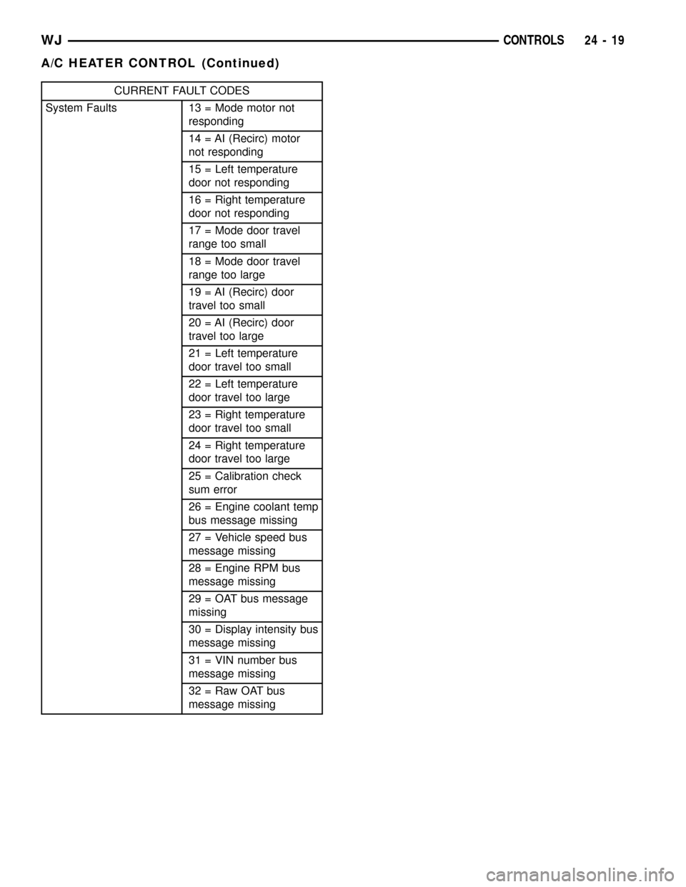
CURRENT FAULT CODES
System Faults 13 = Mode motor not
responding
14 = AI (Recirc) motor
not responding
15 = Left temperature
door not responding
16 = Right temperature
door not responding
17 = Mode door travel
range too small
18 = Mode door travel
range too large
19 = AI (Recirc) door
travel too small
20 = AI (Recirc) door
travel too large
21 = Left temperature
door travel too small
22 = Left temperature
door travel too large
23 = Right temperature
door travel too small
24 = Right temperature
door travel too large
25 = Calibration check
sum error
26 = Engine coolant temp
bus message missing
27 = Vehicle speed bus
message missing
28 = Engine RPM bus
message missing
29 = OAT bus message
missing
30 = Display intensity bus
message missing
31 = VIN number bus
message missing
32 = Raw OAT bus
message missing
WJCONTROLS 24 - 19
A/C HEATER CONTROL (Continued)
Page 2097 of 2199
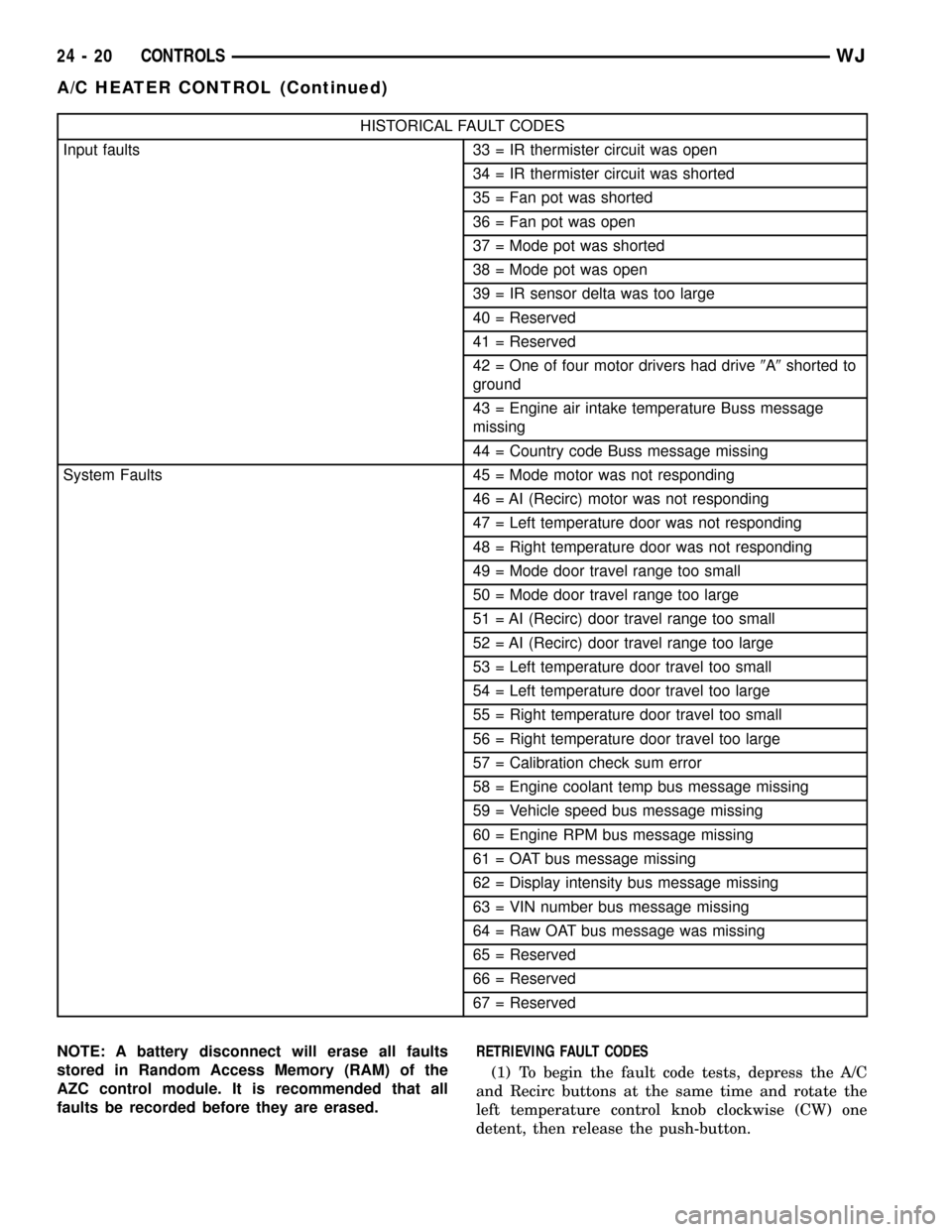
HISTORICAL FAULT CODES
Input faults 33 = IR thermister circuit was open
34 = IR thermister circuit was shorted
35 = Fan pot was shorted
36 = Fan pot was open
37 = Mode pot was shorted
38 = Mode pot was open
39 = IR sensor delta was too large
40 = Reserved
41 = Reserved
42 = One of four motor drivers had drive9A9shorted to
ground
43 = Engine air intake temperature Buss message
missing
44 = Country code Buss message missing
System Faults 45 = Mode motor was not responding
46 = AI (Recirc) motor was not responding
47 = Left temperature door was not responding
48 = Right temperature door was not responding
49 = Mode door travel range too small
50 = Mode door travel range too large
51 = AI (Recirc) door travel range too small
52 = AI (Recirc) door travel range too large
53 = Left temperature door travel too small
54 = Left temperature door travel too large
55 = Right temperature door travel too small
56 = Right temperature door travel too large
57 = Calibration check sum error
58 = Engine coolant temp bus message missing
59 = Vehicle speed bus message missing
60 = Engine RPM bus message missing
61 = OAT bus message missing
62 = Display intensity bus message missing
63 = VIN number bus message missing
64 = Raw OAT bus message was missing
65 = Reserved
66 = Reserved
67 = Reserved
NOTE: A battery disconnect will erase all faults
stored in Random Access Memory (RAM) of the
AZC control module. It is recommended that all
faults be recorded before they are erased.RETRIEVING FAULT CODES
(1) To begin the fault code tests, depress the A/C
and Recirc buttons at the same time and rotate the
left temperature control knob clockwise (CW) one
detent, then release the push-button.
24 - 20 CONTROLSWJ
A/C HEATER CONTROL (Continued)
Page 2164 of 2199
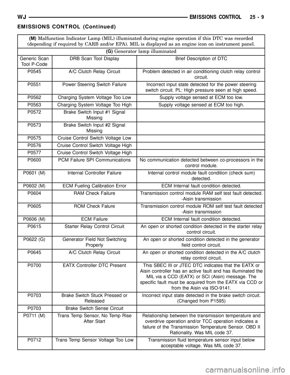
(M)Malfunction Indicator Lamp (MIL) illuminated during engine operation if this DTC was recorded
(depending if required by CARB and/or EPA). MIL is displayed as an engine icon on instrument panel.
(G)Generator lamp illuminated
Generic Scan
Tool P-CodeDRB Scan Tool Display Brief Description of DTC
P0545 A/C Clutch Relay Circuit Problem detected in air conditioning clutch relay control
circuit.
P0551 Power Steering Switch Failure Incorrect input state detected for the power steering
switch circuit. PL: High pressure seen at high speed.
P0562 Charging System Voltage Too Low Supply voltage sensed at ECM too low.
P0563 Charging System Voltage Too High Supply voltage sensed at ECM too high.
P0572 Brake Switch Input #1 Signal
Missing
P0573 Brake Switch Input #2 Signal
Missing
P0575 Cruise Control Switch Voltage Low
P0576 Cruise Control Switch Voltage High
P0577 Cruise Control Switch Voltage High
P0600 PCM Failure SPI Communications No communication detected between co-processors in the
control module.
P0601 (M) Internal Controller Failure Internal control module fault condition (check sum)
detected.
P0602 (M) ECM Fueling Calibration Error ECM Internal fault condition detected.
P0604 RAM Check Failure Transmission control module RAM self test fault detected.
-Aisin transmission
P0605 ROM Check Falure Transmission control module ROM self test fault detected
-Aisin transmission
P0606 (M) ECM Failure ECM Internal fault condition detected.
P0615 Starter Relay Control Circuit An open or shorted condition detected in the starter relay
control circuit.
P0622 (G) Generator Field Not Switching
ProperlyAn open or shorted condition detected in the generator
field control circuit.
P0645 A/C Clutch Relay Circuit An open or shorted condition detected in the A/C clutch
relay control circuit.
P0700 EATX Controller DTC Present This SBEC III or JTEC DTC indicates that the EATX or
Aisin controller has an active fault and has illuminated the
MIL via a CCD (EATX) or SCI (Aisin) message. The
specific fault must be acquired from the EATX via CCD or
from the Aisin via ISO-9141.
P0703 Brake Switch Stuck Pressed or
ReleasedIncorrect input state detected in the brake switch circuit.
(Changed from P1595)
P0703 Brake Switch Sense Circuit
P0711 (M) Trans Temp Sensor, No Temp Rise
After StartRelationship between the transmission temperature and
overdrive operation and/or TCC operation indicates a
failure of the Transmission Temperature Sensor. OBD II
Rationality. Was MIL code 37.
P0712 Trans Temp Sensor Voltage Too Low Transmission fluid temperature sensor input below
acceptable voltage. Was MIL code 37.
WJEMISSIONS CONTROL 25 - 9
EMISSIONS CONTROL (Continued)
Page 2169 of 2199
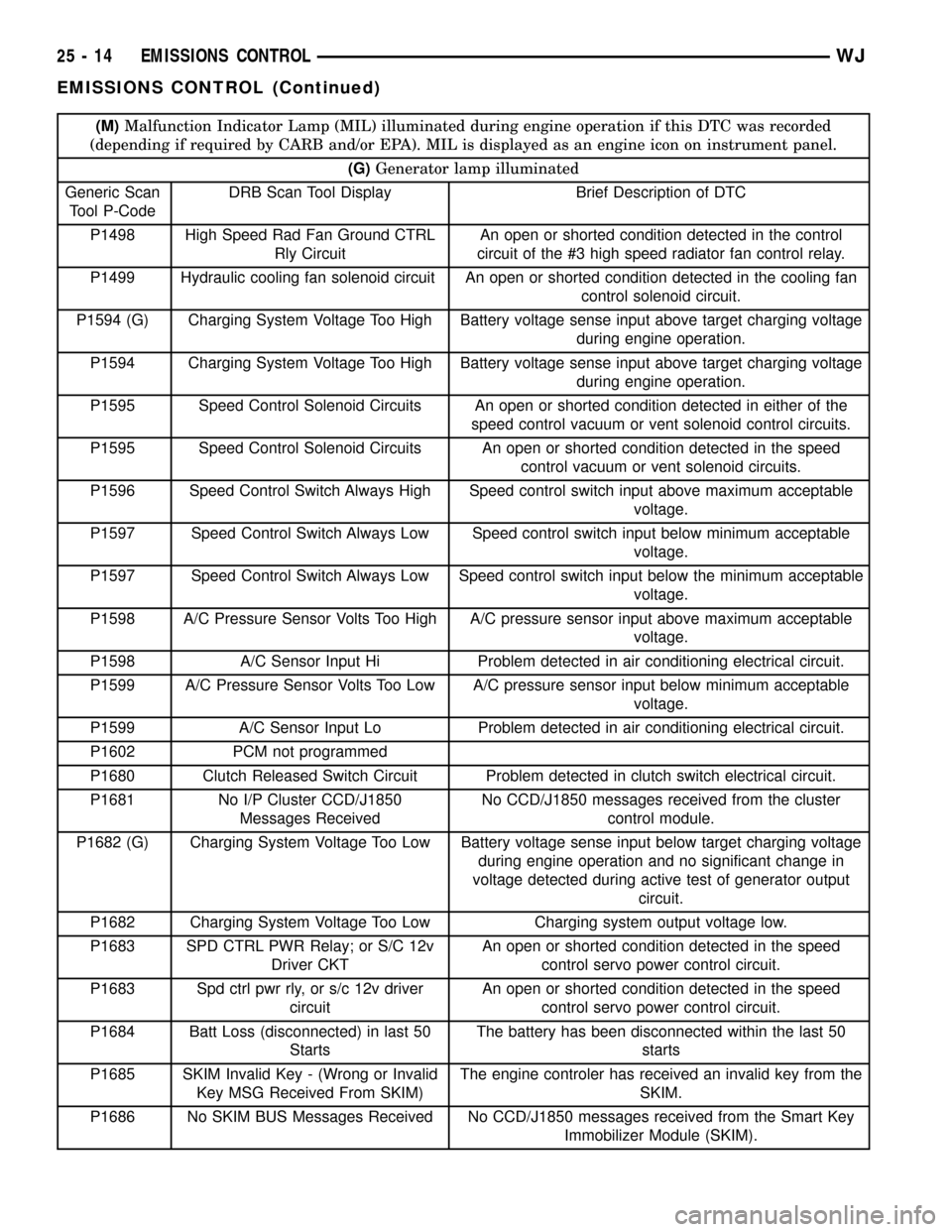
(M)Malfunction Indicator Lamp (MIL) illuminated during engine operation if this DTC was recorded
(depending if required by CARB and/or EPA). MIL is displayed as an engine icon on instrument panel.
(G)Generator lamp illuminated
Generic Scan
Tool P-CodeDRB Scan Tool Display Brief Description of DTC
P1498 High Speed Rad Fan Ground CTRL
Rly CircuitAn open or shorted condition detected in the control
circuit of the #3 high speed radiator fan control relay.
P1499 Hydraulic cooling fan solenoid circuit An open or shorted condition detected in the cooling fan
control solenoid circuit.
P1594 (G) Charging System Voltage Too High Battery voltage sense input above target charging voltage
during engine operation.
P1594 Charging System Voltage Too High Battery voltage sense input above target charging voltage
during engine operation.
P1595 Speed Control Solenoid Circuits An open or shorted condition detected in either of the
speed control vacuum or vent solenoid control circuits.
P1595 Speed Control Solenoid Circuits An open or shorted condition detected in the speed
control vacuum or vent solenoid circuits.
P1596 Speed Control Switch Always High Speed control switch input above maximum acceptable
voltage.
P1597 Speed Control Switch Always Low Speed control switch input below minimum acceptable
voltage.
P1597 Speed Control Switch Always Low Speed control switch input below the minimum acceptable
voltage.
P1598 A/C Pressure Sensor Volts Too High A/C pressure sensor input above maximum acceptable
voltage.
P1598 A/C Sensor Input Hi Problem detected in air conditioning electrical circuit.
P1599 A/C Pressure Sensor Volts Too Low A/C pressure sensor input below minimum acceptable
voltage.
P1599 A/C Sensor Input Lo Problem detected in air conditioning electrical circuit.
P1602 PCM not programmed
P1680 Clutch Released Switch Circuit Problem detected in clutch switch electrical circuit.
P1681 No I/P Cluster CCD/J1850
Messages ReceivedNo CCD/J1850 messages received from the cluster
control module.
P1682 (G) Charging System Voltage Too Low Battery voltage sense input below target charging voltage
during engine operation and no significant change in
voltage detected during active test of generator output
circuit.
P1682 Charging System Voltage Too Low Charging system output voltage low.
P1683 SPD CTRL PWR Relay; or S/C 12v
Driver CKTAn open or shorted condition detected in the speed
control servo power control circuit.
P1683 Spd ctrl pwr rly, or s/c 12v driver
circuitAn open or shorted condition detected in the speed
control servo power control circuit.
P1684 Batt Loss (disconnected) in last 50
StartsThe battery has been disconnected within the last 50
starts
P1685 SKIM Invalid Key - (Wrong or Invalid
Key MSG Received From SKIM)The engine controler has received an invalid key from the
SKIM.
P1686 No SKIM BUS Messages Received No CCD/J1850 messages received from the Smart Key
Immobilizer Module (SKIM).
25 - 14 EMISSIONS CONTROLWJ
EMISSIONS CONTROL (Continued)
Page 2170 of 2199
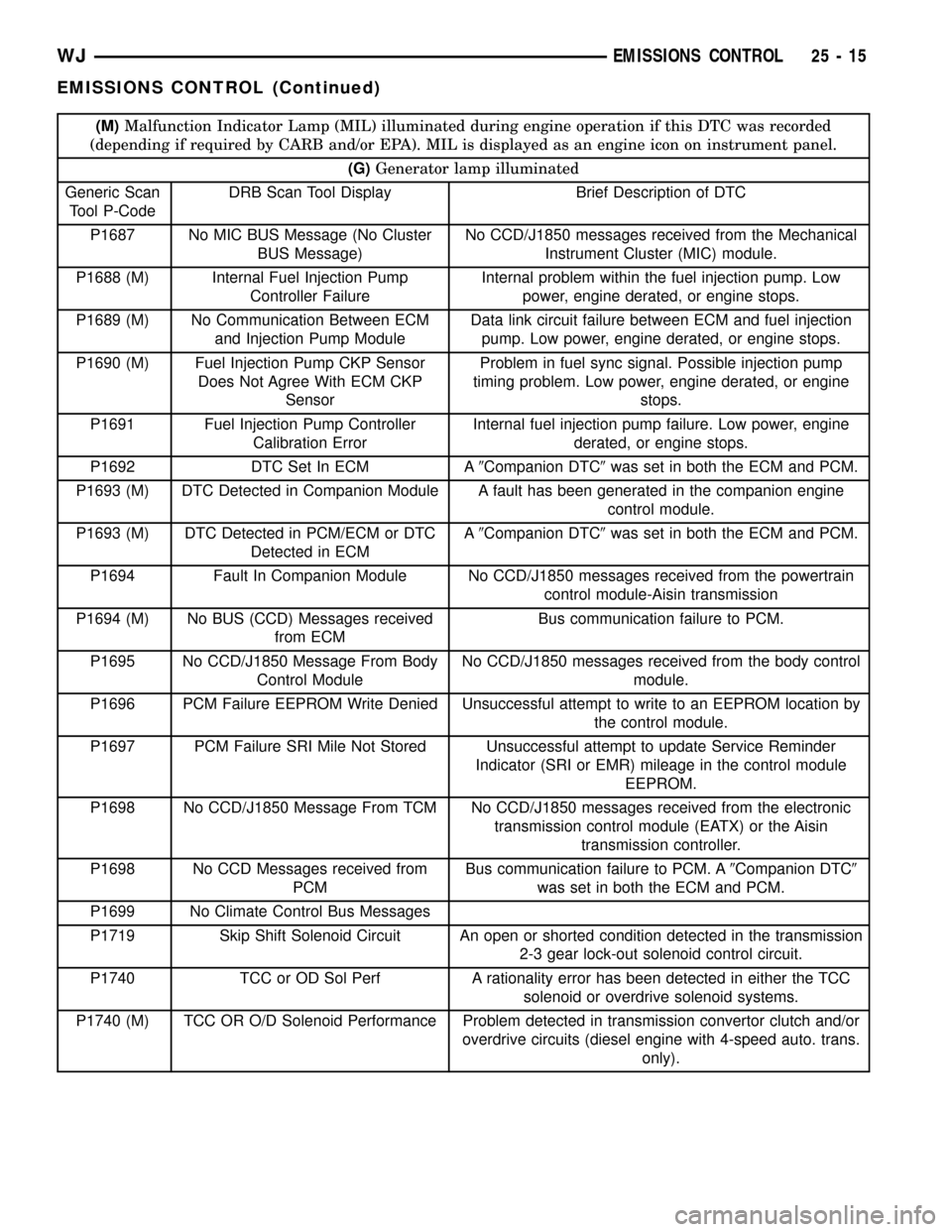
(M)Malfunction Indicator Lamp (MIL) illuminated during engine operation if this DTC was recorded
(depending if required by CARB and/or EPA). MIL is displayed as an engine icon on instrument panel.
(G)Generator lamp illuminated
Generic Scan
Tool P-CodeDRB Scan Tool Display Brief Description of DTC
P1687 No MIC BUS Message (No Cluster
BUS Message)No CCD/J1850 messages received from the Mechanical
Instrument Cluster (MIC) module.
P1688 (M) Internal Fuel Injection Pump
Controller FailureInternal problem within the fuel injection pump. Low
power, engine derated, or engine stops.
P1689 (M) No Communication Between ECM
and Injection Pump ModuleData link circuit failure between ECM and fuel injection
pump. Low power, engine derated, or engine stops.
P1690 (M) Fuel Injection Pump CKP Sensor
Does Not Agree With ECM CKP
SensorProblem in fuel sync signal. Possible injection pump
timing problem. Low power, engine derated, or engine
stops.
P1691 Fuel Injection Pump Controller
Calibration ErrorInternal fuel injection pump failure. Low power, engine
derated, or engine stops.
P1692 DTC Set In ECM A9Companion DTC9was set in both the ECM and PCM.
P1693 (M) DTC Detected in Companion Module A fault has been generated in the companion engine
control module.
P1693 (M) DTC Detected in PCM/ECM or DTC
Detected in ECMA9Companion DTC9was set in both the ECM and PCM.
P1694 Fault In Companion Module No CCD/J1850 messages received from the powertrain
control module-Aisin transmission
P1694 (M) No BUS (CCD) Messages received
from ECMBus communication failure to PCM.
P1695 No CCD/J1850 Message From Body
Control ModuleNo CCD/J1850 messages received from the body control
module.
P1696 PCM Failure EEPROM Write Denied Unsuccessful attempt to write to an EEPROM location by
the control module.
P1697 PCM Failure SRI Mile Not Stored Unsuccessful attempt to update Service Reminder
Indicator (SRI or EMR) mileage in the control module
EEPROM.
P1698 No CCD/J1850 Message From TCM No CCD/J1850 messages received from the electronic
transmission control module (EATX) or the Aisin
transmission controller.
P1698 No CCD Messages received from
PCMBus communication failure to PCM. A9Companion DTC9
was set in both the ECM and PCM.
P1699 No Climate Control Bus Messages
P1719 Skip Shift Solenoid Circuit An open or shorted condition detected in the transmission
2-3 gear lock-out solenoid control circuit.
P1740 TCC or OD Sol Perf A rationality error has been detected in either the TCC
solenoid or overdrive solenoid systems.
P1740 (M) TCC OR O/D Solenoid Performance Problem detected in transmission convertor clutch and/or
overdrive circuits (diesel engine with 4-speed auto. trans.
only).
WJEMISSIONS CONTROL 25 - 15
EMISSIONS CONTROL (Continued)