2003 JEEP GRAND CHEROKEE Lock cylinder
[x] Cancel search: Lock cylinderPage 1273 of 2199
ENGINE BLOCK
CLEANING
Thoroughly clean the oil pan and engine block gas-
ket surfaces.
Use compressed air to clean out:
²The galley at the oil filter adaptor hole.
²The front and rear oil galley holes.
²The feed holes for the crankshaft main bearings.
Once the block has been completely cleaned, apply
Loctite PST pipe sealant with Teflon 592 to the
threads of the front and rear oil galley plugs. Tighten
the plugs to 34 N´m (25 ft. lbs.) torque.
INSPECTION
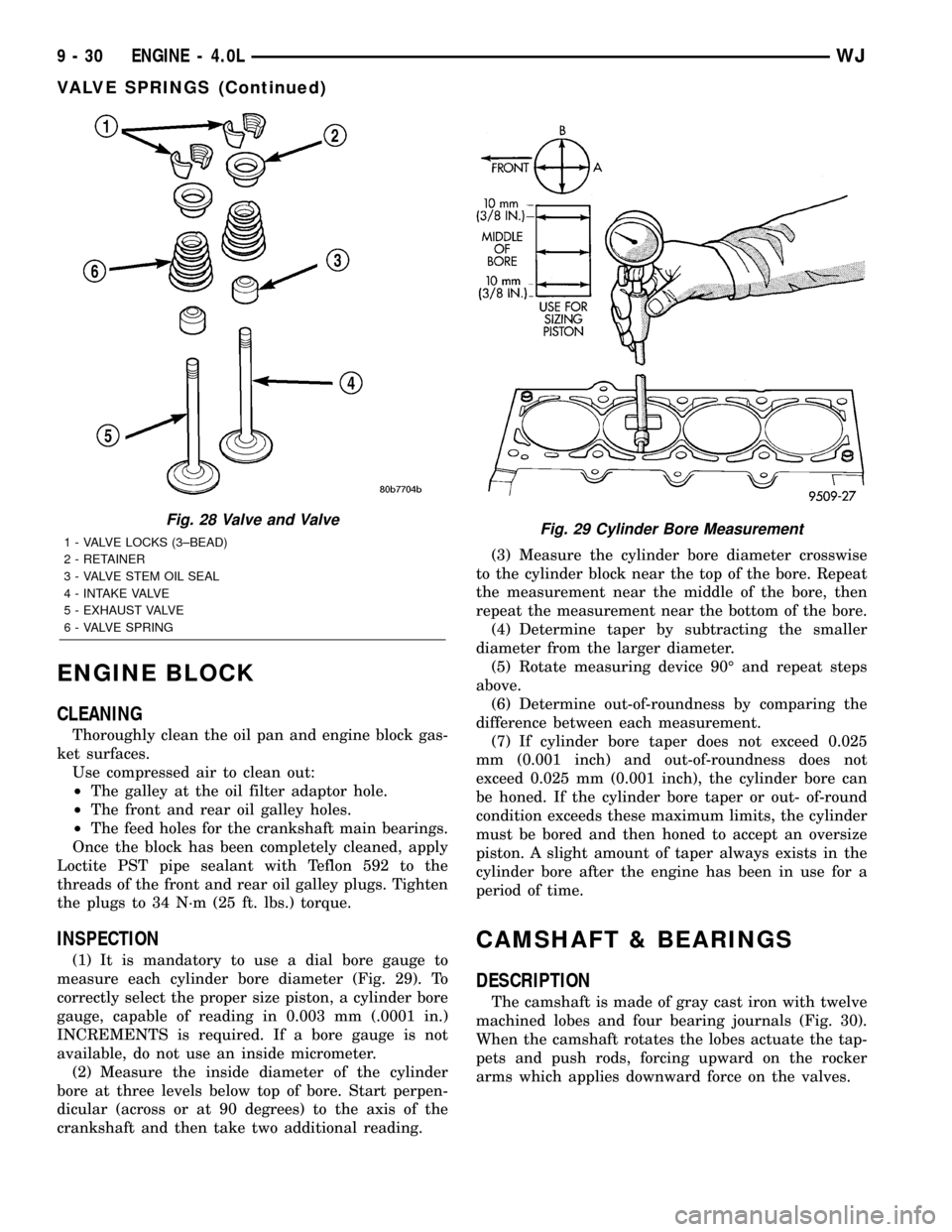
(1) It is mandatory to use a dial bore gauge to
measure each cylinder bore diameter (Fig. 29). To
correctly select the proper size piston, a cylinder bore
gauge, capable of reading in 0.003 mm (.0001 in.)
INCREMENTS is required. If a bore gauge is not
available, do not use an inside micrometer.
(2) Measure the inside diameter of the cylinder
bore at three levels below top of bore. Start perpen-
dicular (across or at 90 degrees) to the axis of the
crankshaft and then take two additional reading.(3) Measure the cylinder bore diameter crosswise
to the cylinder block near the top of the bore. Repeat
the measurement near the middle of the bore, then
repeat the measurement near the bottom of the bore.
(4) Determine taper by subtracting the smaller
diameter from the larger diameter.
(5) Rotate measuring device 90É and repeat steps
above.
(6) Determine out-of-roundness by comparing the
difference between each measurement.
(7) If cylinder bore taper does not exceed 0.025
mm (0.001 inch) and out-of-roundness does not
exceed 0.025 mm (0.001 inch), the cylinder bore can
be honed. If the cylinder bore taper or out- of-round
condition exceeds these maximum limits, the cylinder
must be bored and then honed to accept an oversize
piston. A slight amount of taper always exists in the
cylinder bore after the engine has been in use for a
period of time.
CAMSHAFT & BEARINGS
DESCRIPTION
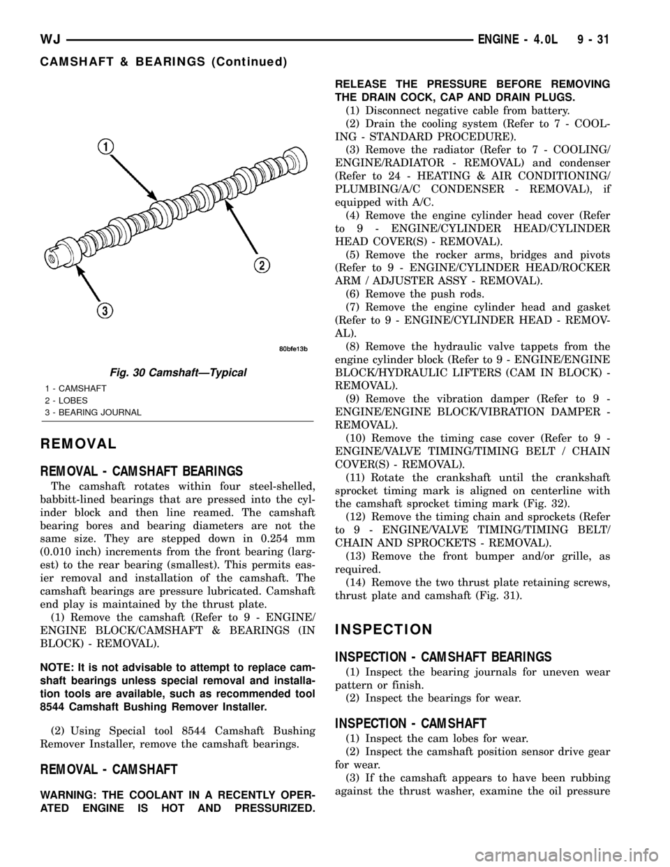
The camshaft is made of gray cast iron with twelve
machined lobes and four bearing journals (Fig. 30).
When the camshaft rotates the lobes actuate the tap-
pets and push rods, forcing upward on the rocker
arms which applies downward force on the valves.
Fig. 28 Valve and Valve
1 - VALVE LOCKS (3±BEAD)
2 - RETAINER
3 - VALVE STEM OIL SEAL
4 - INTAKE VALVE
5 - EXHAUST VALVE
6 - VALVE SPRINGFig. 29 Cylinder Bore Measurement
9 - 30 ENGINE - 4.0LWJ
VALVE SPRINGS (Continued)
Page 1274 of 2199
REMOVAL
REMOVAL - CAMSHAFT BEARINGS
The camshaft rotates within four steel-shelled,
babbitt-lined bearings that are pressed into the cyl-
inder block and then line reamed. The camshaft
bearing bores and bearing diameters are not the
same size. They are stepped down in 0.254 mm
(0.010 inch) increments from the front bearing (larg-
est) to the rear bearing (smallest). This permits eas-
ier removal and installation of the camshaft. The
camshaft bearings are pressure lubricated. Camshaft
end play is maintained by the thrust plate.
(1) Remove the camshaft (Refer to 9 - ENGINE/
ENGINE BLOCK/CAMSHAFT & BEARINGS (IN
BLOCK) - REMOVAL).
NOTE: It is not advisable to attempt to replace cam-
shaft bearings unless special removal and installa-
tion tools are available, such as recommended tool
8544 Camshaft Bushing Remover Installer.
(2) Using Special tool 8544 Camshaft Bushing
Remover Installer, remove the camshaft bearings.
REMOVAL - CAMSHAFT
WARNING: THE COOLANT IN A RECENTLY OPER-
ATED ENGINE IS HOT AND PRESSURIZED.RELEASE THE PRESSURE BEFORE REMOVING
THE DRAIN COCK, CAP AND DRAIN PLUGS.
(1) Disconnect negative cable from battery.
(2) Drain the cooling system (Refer to 7 - COOL-
ING - STANDARD PROCEDURE).
(3) Remove the radiator (Refer to 7 - COOLING/
ENGINE/RADIATOR - REMOVAL) and condenser
(Refer to 24 - HEATING & AIR CONDITIONING/
PLUMBING/A/C CONDENSER - REMOVAL), if
equipped with A/C.
(4) Remove the engine cylinder head cover (Refer
to 9 - ENGINE/CYLINDER HEAD/CYLINDER
HEAD COVER(S) - REMOVAL).
(5) Remove the rocker arms, bridges and pivots
(Refer to 9 - ENGINE/CYLINDER HEAD/ROCKER
ARM / ADJUSTER ASSY - REMOVAL).
(6) Remove the push rods.
(7) Remove the engine cylinder head and gasket
(Refer to 9 - ENGINE/CYLINDER HEAD - REMOV-
AL).
(8) Remove the hydraulic valve tappets from the
engine cylinder block (Refer to 9 - ENGINE/ENGINE
BLOCK/HYDRAULIC LIFTERS (CAM IN BLOCK) -
REMOVAL).
(9) Remove the vibration damper (Refer to 9 -
ENGINE/ENGINE BLOCK/VIBRATION DAMPER -
REMOVAL).
(10) Remove the timing case cover (Refer to 9 -
ENGINE/VALVE TIMING/TIMING BELT / CHAIN
COVER(S) - REMOVAL).
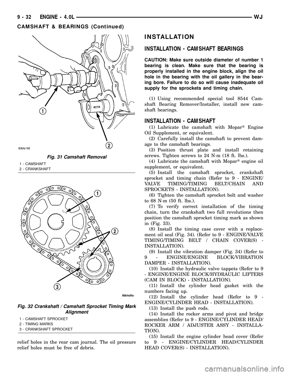
(11) Rotate the crankshaft until the crankshaft
sprocket timing mark is aligned on centerline with
the camshaft sprocket timing mark (Fig. 32).
(12) Remove the timing chain and sprockets (Refer
to 9 - ENGINE/VALVE TIMING/TIMING BELT/
CHAIN AND SPROCKETS - REMOVAL).
(13) Remove the front bumper and/or grille, as
required.
(14) Remove the two thrust plate retaining screws,
thrust plate and camshaft (Fig. 31).
INSPECTION
INSPECTION - CAMSHAFT BEARINGS
(1) Inspect the bearing journals for uneven wear
pattern or finish.
(2) Inspect the bearings for wear.
INSPECTION - CAMSHAFT
(1) Inspect the cam lobes for wear.
(2) Inspect the camshaft position sensor drive gear
for wear.
(3) If the camshaft appears to have been rubbing
against the thrust washer, examine the oil pressure
Fig. 30 CamshaftÐTypical
1 - CAMSHAFT
2 - LOBES
3 - BEARING JOURNAL
WJENGINE - 4.0L 9 - 31
CAMSHAFT & BEARINGS (Continued)
Page 1275 of 2199
relief holes in the rear cam journal. The oil pressure
relief holes must be free of debris.
INSTALLATION
INSTALLATION - CAMSHAFT BEARINGS
CAUTION: Make sure outside diameter of number 1
bearing is clean. Make sure that the bearing is
properly installed in the engine block, align the oil
hole in the bearing with the oil gallery in the bear-
ing bore. Failure to do so will cause inadequate oil
supply for the sprockets and timing chain.
(1) Using recommended special tool 8544 Cam-
shaft Bearing Remover/Installer, install new cam-
shaft bearings.
INSTALLATION - CAMSHAFT
(1) Lubricate the camshaft with MopartEngine
Oil Supplement, or equivalent.
(2) Carefully install the camshaft to prevent dam-
age to the camshaft bearings.
(3) Position thrust plate and install retaining
screws. Tighten screws to 24 N´m (18 ft. lbs.).
(4) Lubricate the camshaft with Mopartengine oil
supplement, or equivalent.
(5) Install the camshaft sprocket, crankshaft
sprocket and timing chain (Refer to 9 - ENGINE/
VALVE TIMING/TIMING BELT/CHAIN AND
SPROCKETS - INSTALLATION).
(6) Tighten the camshaft sprocket bolt and washer
to 68 N´m (50 ft. lbs.).
(7) To verify correct installation of the timing
chain, turn the crankshaft two full revolutions then
position the camshaft sprocket timing mark as shown
in (Fig. 33).
(8) Install the timing case cover with a replace-
ment oil seal (Fig. 34). (Refer to 9 - ENGINE/VALVE
TIMING/TIMING BELT / CHAIN COVER(S) -
INSTALLATION).
(9) Install the vibration damper (Fig. 34) (Refer to
9 - ENGINE/ENGINE BLOCK/VIBRATION
DAMPER - INSTALLATION).
(10) Install the hydraulic valve tappets (Refer to 9
- ENGINE/ENGINE BLOCK/HYDRAULIC LIFTERS
(CAM IN BLOCK) - INSTALLATION).
(11) Install the cylinder head gasket with the
numbers facing up.
(12) Install the cylinder head (Refer to 9 -
ENGINE/CYLINDER HEAD - INSTALLATION).
(13) Install the push rods.
(14) Install the rocker arms and pivot and bridge
assemblies (Refer to 9 - ENGINE/CYLINDER HEAD/
ROCKER ARM / ADJUSTER ASSY - INSTALLA-
TION).
(15) Install the engine cylinder head cover (Refer
to 9 - ENGINE/CYLINDER HEAD/CYLINDER
HEAD COVER(S) - INSTALLATION).
Fig. 31 Camshaft Removal
1 - CAMSHAFT
2 - CRANKSHAFT
Fig. 32 Crankshaft / Camshaft Sprocket Timing Mark
Alignment
1 - CAMSHAFT SPROCKET
2 - TIMING MARKS
3 - CRANKSHAFT SPROCKET
9 - 32 ENGINE - 4.0LWJ
CAMSHAFT & BEARINGS (Continued)
Page 1279 of 2199
CRANKSHAFT MAIN
BEARINGS
STANDARD PROCEDURE - FITTING
CRANKSHAFT MAIN BEARINGS
FITTING BEARINGS (CRANKSHAFT INSTALLED)
The main bearing caps, numbered (front to rear)
from 1 through 7 have an arrow to indicate the for-
ward position. The upper main bearing inserts are
grooved to provide oil channels while the lower
inserts are smooth.
Each bearing insert pair is selectively fitted to its
respective journal to obtain the specified operating
clearance. In production, the select fit is obtained by
using various-sized color-coded bearing insert pairs
as listed in the Main Bearing Fitting Chart. The
bearing color code appears on the edge of the insert.
The size is not stamped on bearing inserts used
for engine production.
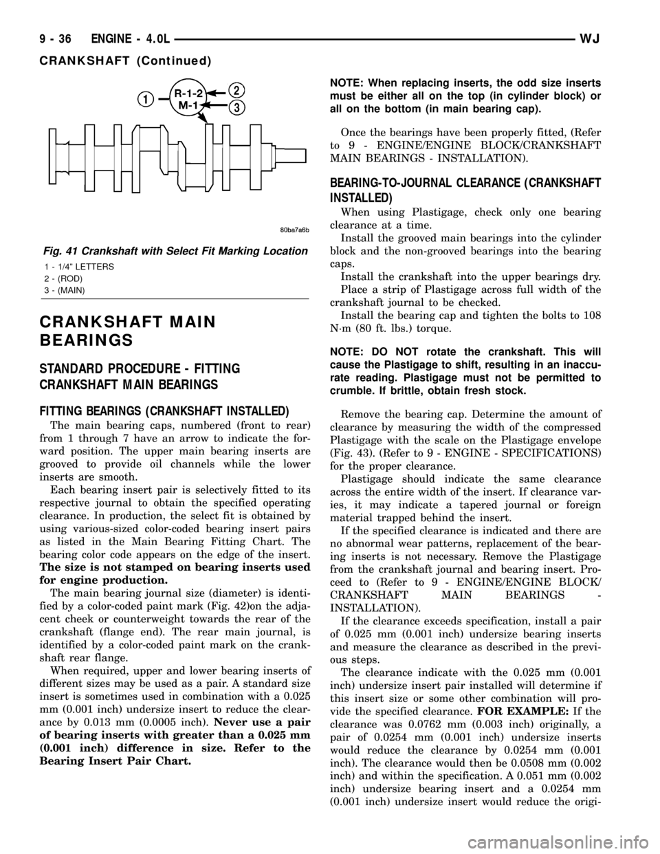
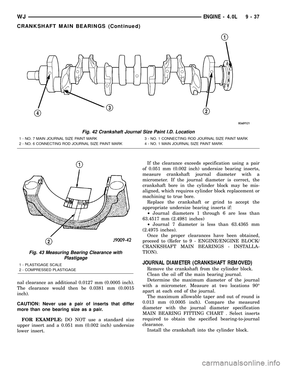
The main bearing journal size (diameter) is identi-
fied by a color-coded paint mark (Fig. 42)on the adja-
cent cheek or counterweight towards the rear of the
crankshaft (flange end). The rear main journal, is
identified by a color-coded paint mark on the crank-
shaft rear flange.
When required, upper and lower bearing inserts of
different sizes may be used as a pair. A standard size
insert is sometimes used in combination with a 0.025
mm (0.001 inch) undersize insert to reduce the clear-
ance by 0.013 mm (0.0005 inch).Never use a pair
of bearing inserts with greater than a 0.025 mm
(0.001 inch) difference in size. Refer to the
Bearing Insert Pair Chart.NOTE: When replacing inserts, the odd size inserts
must be either all on the top (in cylinder block) or
all on the bottom (in main bearing cap).
Once the bearings have been properly fitted, (Refer
to 9 - ENGINE/ENGINE BLOCK/CRANKSHAFT
MAIN BEARINGS - INSTALLATION).
BEARING-TO-JOURNAL CLEARANCE (CRANKSHAFT
INSTALLED)
When using Plastigage, check only one bearing
clearance at a time.
Install the grooved main bearings into the cylinder
block and the non-grooved bearings into the bearing
caps.
Install the crankshaft into the upper bearings dry.
Place a strip of Plastigage across full width of the
crankshaft journal to be checked.
Install the bearing cap and tighten the bolts to 108
N´m (80 ft. lbs.) torque.
NOTE: DO NOT rotate the crankshaft. This will
cause the Plastigage to shift, resulting in an inaccu-
rate reading. Plastigage must not be permitted to
crumble. If brittle, obtain fresh stock.
Remove the bearing cap. Determine the amount of
clearance by measuring the width of the compressed
Plastigage with the scale on the Plastigage envelope
(Fig. 43). (Refer to 9 - ENGINE - SPECIFICATIONS)
for the proper clearance.
Plastigage should indicate the same clearance
across the entire width of the insert. If clearance var-
ies, it may indicate a tapered journal or foreign
material trapped behind the insert.
If the specified clearance is indicated and there are
no abnormal wear patterns, replacement of the bear-
ing inserts is not necessary. Remove the Plastigage
from the crankshaft journal and bearing insert. Pro-
ceed to (Refer to 9 - ENGINE/ENGINE BLOCK/
CRANKSHAFT MAIN BEARINGS -
INSTALLATION).
If the clearance exceeds specification, install a pair
of 0.025 mm (0.001 inch) undersize bearing inserts
and measure the clearance as described in the previ-
ous steps.
The clearance indicate with the 0.025 mm (0.001
inch) undersize insert pair installed will determine if
this insert size or some other combination will pro-
vide the specified clearance.FOR EXAMPLE:If the
clearance was 0.0762 mm (0.003 inch) originally, a
pair of 0.0254 mm (0.001 inch) undersize inserts
would reduce the clearance by 0.0254 mm (0.001
inch). The clearance would then be 0.0508 mm (0.002
inch) and within the specification. A 0.051 mm (0.002
inch) undersize bearing insert and a 0.0254 mm
(0.001 inch) undersize insert would reduce the origi-
Fig. 41 Crankshaft with Select Fit Marking Location
1 - 1/4º LETTERS
2 - (ROD)
3 - (MAIN)
9 - 36 ENGINE - 4.0LWJ
CRANKSHAFT (Continued)
Page 1280 of 2199
nal clearance an additional 0.0127 mm (0.0005 inch).
The clearance would then be 0.0381 mm (0.0015
inch).
CAUTION: Never use a pair of inserts that differ
more than one bearing size as a pair.
FOR EXAMPLE:DO NOT use a standard size
upper insert and a 0.051 mm (0.002 inch) undersize
lower insert.If the clearance exceeds specification using a pair
of 0.051 mm (0.002 inch) undersize bearing inserts,
measure crankshaft journal diameter with a
micrometer. If the journal diameter is correct, the
crankshaft bore in the cylinder block may be mis-
aligned, which requires cylinder block replacement or
machining to true bore.
Replace the crankshaft or grind to accept the
appropriate undersize bearing inserts if:
²Journal diameters 1 through 6 are less than
63.4517 mm (2.4981 inches)
²Journal 7 diameter is less than 63.4365 mm
(2.4975 inches).
Once the proper clearances have been obtained,
proceed to (Refer to 9 - ENGINE/ENGINE BLOCK/
CRANKSHAFT MAIN BEARINGS - INSTALLA-
TION).
JOURNAL DIAMETER (CRANKSHAFT REMOVED)
Remove the crankshaft from the cylinder block.
Clean the oil off the main bearing journal.
Determine the maximum diameter of the journal
with a micrometer. Measure at two locations 90É
apart at each end of the journal.
The maximum allowable taper and out of round is
0.013 mm (0.0005 inch). Compare the measured
diameter with the journal diameter specification
MAIN BEARING FITTING CHART . Select inserts
required to obtain the specified bearing-to-journal
clearance.
Install the crankshaft into the cylinder block.
Fig. 42 Crankshaft Journal Size Paint I.D. Location
1 - NO. 7 MAIN JOURNAL SIZE PAINT MARK
2 - NO. 6 CONNECTING ROD JOURNAL SIZE PAINT MARK3 - NO. 1 CONNECTING ROD JOURNAL SIZE PAINT MARK
4 - NO. 1 MAIN JOURNAL SIZE PAINT MARK
Fig. 43 Measuring Bearing Clearance with
Plastigage
1 - PLASTIGAGE SCALE
2 - COMPRESSED PLASTIGAGE
WJENGINE - 4.0L 9 - 37
CRANKSHAFT MAIN BEARINGS (Continued)
Page 1283 of 2199
INSPECTION
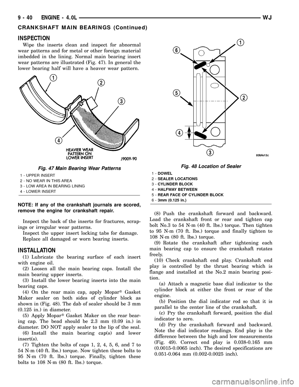
Wipe the inserts clean and inspect for abnormal
wear patterns and for metal or other foreign material
imbedded in the lining. Normal main bearing insert
wear patterns are illustrated (Fig. 47). In general the
lower bearing half will have a heaver wear pattern.
NOTE: If any of the crankshaft journals are scored,
remove the engine for crankshaft repair.
Inspect the back of the inserts for fractures, scrap-
ings or irregular wear patterns.
Inspect the upper insert locking tabs for damage.
Replace all damaged or worn bearing inserts.
INSTALLATION
(1) Lubricate the bearing surface of each insert
with engine oil.
(2) Loosen all the main bearing caps. Install the
main bearing upper inserts.
(3) Install the lower bearing inserts into the main
bearing caps.
(4) On the rear main cap, apply MopartGasket
Maker sealer on both sides of cylinder block as
shown in (Fig. 48). The dab of sealer should be 3 mm
(0.125 in.) in diameter.
(5) Apply MopartGasket Maker on the rear bear-
ing cap. The bead should be 2.3 mm (0.09 in.) in
diameter. DO NOT apply sealer to the lip of the seal.
(6) Install the main bearing cap(s) and lower
insert(s).
(7) Tighten the bolts of caps 1, 2, 4, 5, 6, and 7 to
54 N´m (40 ft. lbs.) torque. Now tighten these bolts to
95 N´m (70 ft. lbs.) torque. Finally, tighten these
bolts to 108 N´m (80 ft. lbs.) torque.(8) Push the crankshaft forward and backward.
Load the crankshaft front or rear and tighten cap
bolt No.3 to 54 N´m (40 ft. lbs.) torque. Then tighten
to 95 N´m (70 ft. lbs.) torque and finally tighten to
108 N´m (80 ft. lbs.) torque.
(9) Rotate the crankshaft after tightening each
main bearing cap to ensure the crankshaft rotates
freely.
(10) Check crankshaft end play. Crankshaft end
play is controlled by the thrust bearing which is
flange and installed at the No.2 main bearing posi-
tion.
(a) Attach a magnetic base dial indicator to the
cylinder block at either the front or rear of the
engine.
(b) Position the dial indicator rod so that it is
parallel to the center line of the crankshaft.
(c) Pry the crankshaft forward, position the dial
indicator to zero.
(d) Pry the crankshaft forward and backward.
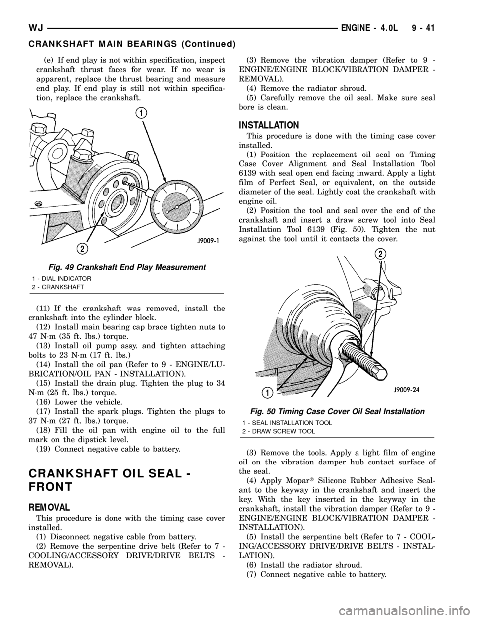
Note the dial indicator readings. End play is the
difference between the high and low measurements
(Fig. 49). Correct end play is 0.038-0.165 mm
(0.0015-0.0065 inch). The desired specifications are
0.051-0.064 mm (0.002-0.0025 inch).
Fig. 47 Main Bearing Wear Patterns
1 - UPPER INSERT
2 - NO WEAR IN THIS AREA
3 - LOW AREA IN BEARING LINING
4 - LOWER INSERT
Fig. 48 Location of Sealer
1-DOWEL
2-SEALER LOCATIONS
3-CYLINDER BLOCK
4-HALFWAY BETWEEN
5-REAR FACE OF CYLINDER BLOCK
6-3mm (0.125 in.)
9 - 40 ENGINE - 4.0LWJ
CRANKSHAFT MAIN BEARINGS (Continued)
Page 1284 of 2199
(e) If end play is not within specification, inspect
crankshaft thrust faces for wear. If no wear is
apparent, replace the thrust bearing and measure
end play. If end play is still not within specifica-
tion, replace the crankshaft.
(11) If the crankshaft was removed, install the
crankshaft into the cylinder block.
(12) Install main bearing cap brace tighten nuts to
47 N´m (35 ft. lbs.) torque.
(13) Install oil pump assy. and tighten attaching
bolts to 23 N´m (17 ft. lbs.)
(14) Install the oil pan (Refer to 9 - ENGINE/LU-
BRICATION/OIL PAN - INSTALLATION).
(15) Install the drain plug. Tighten the plug to 34
N´m (25 ft. lbs.) torque.
(16) Lower the vehicle.
(17) Install the spark plugs. Tighten the plugs to
37 N´m (27 ft. lbs.) torque.
(18) Fill the oil pan with engine oil to the full
mark on the dipstick level.
(19) Connect negative cable to battery.
CRANKSHAFT OIL SEAL -
FRONT
REMOVAL
This procedure is done with the timing case cover
installed.
(1) Disconnect negative cable from battery.
(2) Remove the serpentine drive belt (Refer to 7 -
COOLING/ACCESSORY DRIVE/DRIVE BELTS -
REMOVAL).(3) Remove the vibration damper (Refer to 9 -
ENGINE/ENGINE BLOCK/VIBRATION DAMPER -
REMOVAL).
(4) Remove the radiator shroud.
(5) Carefully remove the oil seal. Make sure seal
bore is clean.
INSTALLATION
This procedure is done with the timing case cover
installed.
(1) Position the replacement oil seal on Timing
Case Cover Alignment and Seal Installation Tool
6139 with seal open end facing inward. Apply a light
film of Perfect Seal, or equivalent, on the outside
diameter of the seal. Lightly coat the crankshaft with
engine oil.
(2) Position the tool and seal over the end of the
crankshaft and insert a draw screw tool into Seal
Installation Tool 6139 (Fig. 50). Tighten the nut
against the tool until it contacts the cover.
(3) Remove the tools. Apply a light film of engine
oil on the vibration damper hub contact surface of
the seal.
(4) Apply MopartSilicone Rubber Adhesive Seal-
ant to the keyway in the crankshaft and insert the
key. With the key inserted in the keyway in the
crankshaft, install the vibration damper (Refer to 9 -
ENGINE/ENGINE BLOCK/VIBRATION DAMPER -
INSTALLATION).
(5) Install the serpentine belt (Refer to 7 - COOL-
ING/ACCESSORY DRIVE/DRIVE BELTS - INSTAL-
LATION).
(6) Install the radiator shroud.
(7) Connect negative cable to battery.
Fig. 49 Crankshaft End Play Measurement
1 - DIAL INDICATOR
2 - CRANKSHAFT
Fig. 50 Timing Case Cover Oil Seal Installation
1 - SEAL INSTALLATION TOOL
2 - DRAW SCREW TOOL
WJENGINE - 4.0L 9 - 41
CRANKSHAFT MAIN BEARINGS (Continued)
Page 1285 of 2199
CRANKSHAFT OIL SEAL -
REAR
REMOVAL
The crankshaft rear main bearing oil seal consists
of two half pieces of viton with a single lip that effec-
tively seals the rear of the crankshaft. Replace the
upper and lower seal halves as a unit to ensure leak-
free operation.
(1) Remove transmission inspection cover.
(2) Remove oil pan. (Refer to 9 - ENGINE/LUBRI-
CATION/OIL PAN - REMOVAL)
(3) Remove main bearing cap brace.
(4) Remove rear main bearing cap (No.7).
(5) Push upper seal out of the groove. Ensure that
the crankshaft and seal groove are not damaged.
(6) Remove lower half of the seal from the bearing
cap.
INSTALLATION
The crankshaft rear main bearing oil seal consists
of two half pieces of viton with a single lip that effec-
tively seals the rear of the crankshaft. Replace the
upper and lower seal halves as a unit to ensure leak-
free operation.
(1) Wipe the seal surface area of the crankshaft
until it is clean.
(2) Apply a thin coat of engine oil.
(3) Coat lip of the seal with engine oil.
(4) Carefully position the upper seal into the
groove in the cylinder block. The lip of the seal faces
toward the front of the engine.
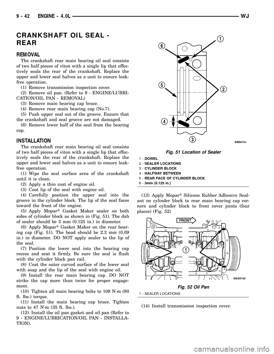
(5) Apply MopartGasket Maker sealer on both
sides of cylinder block as shown in (Fig. 51). The dab
of sealer should be 3 mm (0.125 in.) in diameter.
(6) Apply MopartGasket Maker on the rear bear-
ing cap (Fig. 51). The bead should be 2.3 mm (0.09
in.) in diameter. DO NOT apply sealer to the lip of
the seal.
(7) Position the lower seal into the bearing cap
recess and seat it firmly. Be sure the seal is flush
with the cylinder block pan rail.
(8) Coat the outer curved surface of the lower seal
with soap and the lip of the seal with engine oil.
(9) Install the rear main bearing cap. DO NOT
strike the cap more than twice for proper engage-
ment.
(10) Tighten all main bearing bolts to 108 N´m (80
ft. lbs.) torque.
(11) Install the main bearing cap brace. Tighten
nuts to 47 N´m (35 ft. lbs.).
(12) Install the oil pan gasket and oil pan (Refer to
9 - ENGINE/LUBRICATION/OIL PAN - INSTALLA-
TION).(13) Apply MopartSilicone Rubber Adhesive Seal-
ant on cylinder block to rear main bearing cap cor-
ners and cylinder block to front cover joints (four
places) (Fig. 52)
(14) Install transmission inspection cover.
Fig. 51 Location of Sealer
1-DOWEL
2-SEALER LOCATIONS
3-CYLINDER BLOCK
4-HALFWAY BETWEEN
5-REAR FACE OF CYLINDER BLOCK
6-3mm (0.125 in.)
Fig. 52 Oil Pan
1 - SEALER LOCATIONS
9 - 42 ENGINE - 4.0LWJ