2003 JEEP GRAND CHEROKEE Short to ground
[x] Cancel search: Short to groundPage 1242 of 2199

the vehicle. The power outlet base and mount are
secured by a snap fit within the quarter trim panel.
A plastic protective cap snaps into the power outlet
base when the power outlet is not being used, and
hangs from the power outlet base mount by an inte-
gral bail strap while the power outlet is in use. While
the power outlet is very similar to a cigar lighter
base unit, it does not include the two small spring-
clip retainers inside the bottom of the receptacle
shell that are used to secure the cigar lighter heating
element to the insulated contact.
The power outlet receptacle unit and the accessory
power outlet protective cap are available for service.
The power outlet receptacle cannot be repaired and,
if faulty or damaged, it must be replaced.
OPERATION - REAR POWER OUTLET
The power outlet base or receptacle shell is con-
nected to ground, and an insulated contact in the
bottom of the shell is connected to battery current.
The power outlet receives battery voltage from a fuse
in the Power Distribution Center (PDC) through a
fuse in the Junction Block (JB) at all times. Refer to
Horn/Cigar Lighter/Power Outletin Wiring Dia-
grams for the location of complete rear power outlet
circuit diagrams.
DIAGNOSIS AND TESTING - REAR POWER
OUTLET
Refer toHorn/Cigar Lighter/Power Outletin
Wiring Diagrams for the location of complete rear
power outlet circuit diagrams.
(1) Check the fused B(+) fuse in the Junction
Block (JB). If OK, go to Step 2. If not OK, repair the
shorted circuit or component as required and replace
the faulty fuse.
(2) Check for battery voltage at the fused B(+) fuse
in the JB. If OK, go to Step 3. If not OK, repair the
open fused B(+) circuit to the Power Distribution
Center (PDC) as required.
(3) Remove the plastic protective cap from the rear
power outlet receptacle. Check for continuity between
the inside circumference of the rear power outlet
receptacle and a good ground. There should be conti-
nuity. If OK, go to Step 4. If not OK, go to Step 5.
(4) Check for battery voltage at the insulated con-
tact located at the back of the rear power outlet
receptacle. If not OK, go to Step 5.(5) Disconnect and isolate the battery negative
cable. Remove the rear power outlet from the right
quarter trim panel. Check for continuity between the
ground circuit cavity of the rear power outlet wire
harness connector and a good ground. There should
be continuity. If OK, go to Step 6. If not OK, repair
the open ground circuit to ground as required.
(6) Connect the battery negative cable. Check for
battery voltage at the fused B(+) circuit cavity of the
rear power outlet wire harness connector. If OK,
replace the faulty rear power outlet receptacle base.
If not OK, repair the open fused B(+) circuit to the
JB fuse as required.
REMOVAL
(1) Disconnect and isolate the battery negative
cable.
(2) Pull the protective cap out of the rear power
outlet receptacle base (Fig. 20).
Fig. 20 Rear Power Outlet Remove/Install
1 - RIGHT QUARTER TRIM PANEL
2 - RIGHT BODY WIRE HARNESS CONNECTOR
3 - RECEPTACLE BASE
4 - PROTECTIVE CAP
5 - MOUNT
WJ8W-97 POWER DISTRIBUTION 8W - 97 - 17
REAR POWER OUTLET (Continued)
Page 1462 of 2199

(5) Push sensor against flywheel/drive plate. With
sensor pushed against flywheel/drive plate, tighten
mounting bolt to 7 N´m (60 in. lbs.) torque.
(6) Route sensor wiring harness into wire shield.
(7) Connect sensor pigtail harness electrical con-
nector to main wiring harness.
INSTALLATION - 4.7L
(1) Clean out machined hole in engine block.
(2) Apply a small amount of engine oil to sensor
o-ring.
(3) Install sensor into engine block with a slight
rocking action. Do not twist sensor into position as
damage to o-ring may result.
CAUTION: Before tightening sensor mounting bolt,
be sure sensor is completely flush to cylinder
block. If sensor is not flush, damage to sensor
mounting tang may result.
(4) Install mounting bolt and tighten to 28 N´m
(21 ft. lbs.) torque.
(5) Connect electrical connector to sensor.
(6) Install starter motor. Refer to Starter Removal/
Installation.
FUEL INJECTOR
DESCRIPTION
A separate fuel injector (Fig. 24) is used for each
individual cylinder.
OPERATION
OPERATION
The fuel injectors are electrical solenoids. The
injector contains a pintle that closes off an orifice at
the nozzle end. When electric current is supplied to
the injector, the armature and needle move a short
distance against a spring, allowing fuel to flow out
the orifice. Because the fuel is under high pressure, a
fine spray is developed in the shape of a pencil
stream. The spraying action atomizes the fuel, add-
ing it to the air entering the combustion chamber.
The top (fuel entry) end of the injector (Fig. 24) is
attached into an opening on the fuel rail.
The nozzle (outlet) ends of the injectors are posi-
tioned into openings in the intake manifold just
above the intake valve ports of the cylinder head.
The engine wiring harness connector for each fuel
injector is equipped with an attached numerical tag
(INJ 1, INJ 2 etc.). This is used to identify each fuel
injector.
The injectors are electrically energized, individu-
ally and in a sequential order by the Powertrain Con-
trol Module (PCM). The PCM will adjust injector
pulse width by switching the ground path to each
individual injector on and off. Injector pulse width is
the period of time that the injector is energized. The
PCM will adjust injector pulse width based on vari-
ous inputs it receives.
Battery voltage is supplied to the injectors through
the ASD relay.
The PCM determines injector pulse width based on
various inputs.
OPERATION - PCM OUTPUT
The nozzle ends of the injectors are positioned into
openings in the intake manifold just above the intake
valve ports of the cylinder head. The engine wiring
harness connector for each fuel injector is equipped
with an attached numerical tag (INJ 1, INJ 2 etc.).
This is used to identify each fuel injector with its
respective cylinder number.
The injectors are energized individually in a
sequential order by the Powertrain Control Module
(PCM). The PCM will adjust injector pulse width by
switching the ground path to each individual injector
on and off. Injector pulse width is the period of time
that the injector is energized. The PCM will adjust
injector pulse width based on various inputs it
receives.
Battery voltage (12 volts +) is supplied to the injec-
tors through the ASD relay. The ASD relay will shut-
down the 12 volt power source to the fuel injectors if
the PCM senses the ignition is on, but the engine is
not running. This occurs after the engine has not
been running for approximately 1.8 seconds.
Fig. 24 Fuel InjectorÐ4.0L/4.7L Engines
1 - FUEL INJECTOR
2 - NOZZLE
3 - TOP (FUEL ENTRY)
WJFUEL INJECTION 14 - 43
CRANKSHAFT POSITION SENSOR (Continued)
Page 1491 of 2199

KEY-IN IGNITION SWITCH
DESCRIPTION
The key-in ignition switch is concealed within and
integral to the ignition switch, which is mounted on
the steering column. The key-in ignition switch is
actuated by the ignition lock cylinder mechanism,
and is hard wired between a body ground and the
Body Control Module (BCM) through the instrument
panel wire harness.
The key-in ignition switch cannot be adjusted or
repaired and, if faulty or damaged, the entire igni-
tion switch unit must be replaced,(Refer to 19 -
STEERING/COLUMN/LOCK CYLINDER HOUSING
- REMOVAL). For complete circuit diagrams, refer to
Body Control Modulein the Contents of Wiring
Diagrams.
OPERATION
The key-in ignition switch closes a path to ground
for the BCM when the ignition key is inserted in the
ignition lock cylinder, and opens the ground path
when the key is removed from the ignition lock cyl-
inder. The BCM monitors the key-in ignition switch
status through an internal pull-up, then sends the
proper switch status messages to other electronic
modules over the Programmable Communications
Interface (PCI) data bus network. The key-in ignition
switch status is also used by the BCM as an input
for chime warning system operation.
DIAGNOSIS AND TESTING
KEY-IN IGNITION SWITCH
For complete circuit diagrams, refer toBody Con-
trol Modulein the Contents of Wiring Diagrams.
WARNING: ON VEHICLES EQUIPPED WITH AIR-
BAGS, REFER TO GROUP 8M - PASSIVE
RESTRAINT SYSTEMS BEFORE ATTEMPTING ANY
STEERING WHEEL, STEERING COLUMN, OR
INSTRUMENT PANEL COMPONENT DIAGNOSIS OR
SERVICE. FAILURE TO TAKE THE PROPER PRE-
CAUTIONS COULD RESULT IN ACCIDENTAL AIR-
BAG DEPLOYMENT AND POSSIBLE PERSONAL
INJURY.(1) Disconnect and isolate the battery negative
cable. Disconnect the instrument panel wire harness
connector from the key-in ignition switch connector
receptacle on the ignition switch. Check for continu-
ity between the key-in ignition switch sense and
ground terminals of the key-in ignition switch con-
nector receptacle. There should be continuity with
the key inserted in the ignition lock cylinder, and no
continuity with the key removed from the ignition
lock cylinder. If OK, go to Step 2. If not OK, replace
the faulty ignition switch unit.
(2) Check for continuity between the ground cir-
cuit cavity of the instrument panel wire harness con-
nector for the key-in ignition switch and a good
ground. There should be continuity. If OK, go to Step
3. If not OK, repair the open ground circuit to ground
as required.
(3) Disconnect the gray 26-way instrument panel
wire harness connector from the Body Control Mod-
ule (BCM) connector receptacle. Check for continuity
between the key-in ignition switch sense circuit cav-
ity of the instrument panel wire harness connector
for the key-in ignition switch and a good ground.
There should be no continuity. If OK, go to Step 4. If
not OK, repair the shorted key-in ignition switch
sense circuit as required.
(4) Check for continuity between the key-in igni-
tion switch sense circuit cavities of the instrument
panel wire harness connector for the key-in ignition
switch and the gray 26-way instrument panel wire
harness connector for the BCM. There should be con-
tinuity. If OK, use a DRB scan tool and the proper
Diagnostic Procedures manual to test the BCM. If
not OK, repair the open key-in ignition switch sense
circuit as required.
LOCK CYLINDER
REMOVAL
The ignition key must be in the key cylinder for
cylinder removal. The key cylinder must be removed
first before removing ignition switch.
(1) Disconnect negative battery cable at battery.
(2) If equipped with an automatic transmission,
place shifter in PARK position.
(3) Rotate key to ON position.
19 - 14 COLUMNWJ
Page 1542 of 2199

CONDITION POSSIBLE CAUSES CORRECTION
CLUNK NOISE FROM
DRIVELINE ON
CLOSED THROTTLE
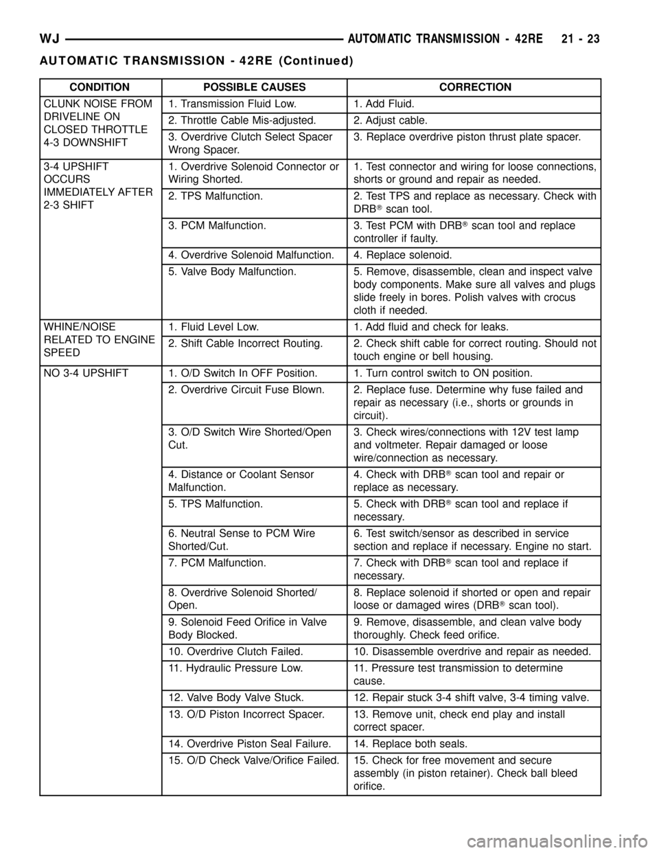
4-3 DOWNSHIFT1. Transmission Fluid Low. 1. Add Fluid.
2. Throttle Cable Mis-adjusted. 2. Adjust cable.
3. Overdrive Clutch Select Spacer
Wrong Spacer.3. Replace overdrive piston thrust plate spacer.
3-4 UPSHIFT
OCCURS
IMMEDIATELY AFTER
2-3 SHIFT1. Overdrive Solenoid Connector or
Wiring Shorted.1.
Test connector and wiring for loose connections,
shorts or ground and repair as needed.
2. TPS Malfunction. 2. Test TPS and replace as necessary. Check with
DRBTscan tool.
3. PCM Malfunction. 3. Test PCM with DRBTscan tool and replace
controller if faulty.
4. Overdrive Solenoid Malfunction. 4. Replace solenoid.
5. Valve Body Malfunction. 5. Remove, disassemble, clean and inspect valve
body components. Make sure all valves and plugs
slide freely in bores. Polish valves with crocus
cloth if needed.
WHINE/NOISE
RELATED TO ENGINE
SPEED1. Fluid Level Low. 1. Add fluid and check for leaks.
2. Shift Cable Incorrect Routing. 2. Check shift cable for correct routing. Should not
touch engine or bell housing.
NO 3-4 UPSHIFT 1. O/D Switch In OFF Position. 1. Turn control switch to ON position.
2. Overdrive Circuit Fuse Blown. 2. Replace fuse. Determine why fuse failed and
repair as necessary (i.e., shorts or grounds in
circuit).
3. O/D Switch Wire Shorted/Open
Cut.3. Check wires/connections with 12V test lamp
and voltmeter. Repair damaged or loose
wire/connection as necessary.
4. Distance or Coolant Sensor
Malfunction.4. Check with DRBTscan tool and repair or
replace as necessary.
5. TPS Malfunction. 5. Check with DRBTscan tool and replace if
necessary.
6. Neutral Sense to PCM Wire
Shorted/Cut.6. Test switch/sensor as described in service
section and replace if necessary. Engine no start.
7. PCM Malfunction. 7. Check with DRBTscan tool and replace if
necessary.
8. Overdrive Solenoid Shorted/
Open.8. Replace solenoid if shorted or open and repair
loose or damaged wires (DRBTscan tool).
9. Solenoid Feed Orifice in Valve
Body Blocked.9. Remove, disassemble, and clean valve body
thoroughly. Check feed orifice.
10. Overdrive Clutch Failed. 10. Disassemble overdrive and repair as needed.
11. Hydraulic Pressure Low. 11. Pressure test transmission to determine
cause.
12. Valve Body Valve Stuck. 12. Repair stuck 3-4 shift valve, 3-4 timing valve.
13. O/D Piston Incorrect Spacer. 13. Remove unit, check end play and install
correct spacer.
14. Overdrive Piston Seal Failure. 14. Replace both seals.
15. O/D Check Valve/Orifice Failed. 15. Check for free movement and secure
assembly (in piston retainer). Check ball bleed
orifice.
WJAUTOMATIC TRANSMISSION - 42RE 21 - 23
AUTOMATIC TRANSMISSION - 42RE (Continued)
Page 1543 of 2199

CONDITION POSSIBLE CAUSES CORRECTION
SLIPS IN OVERDRIVE
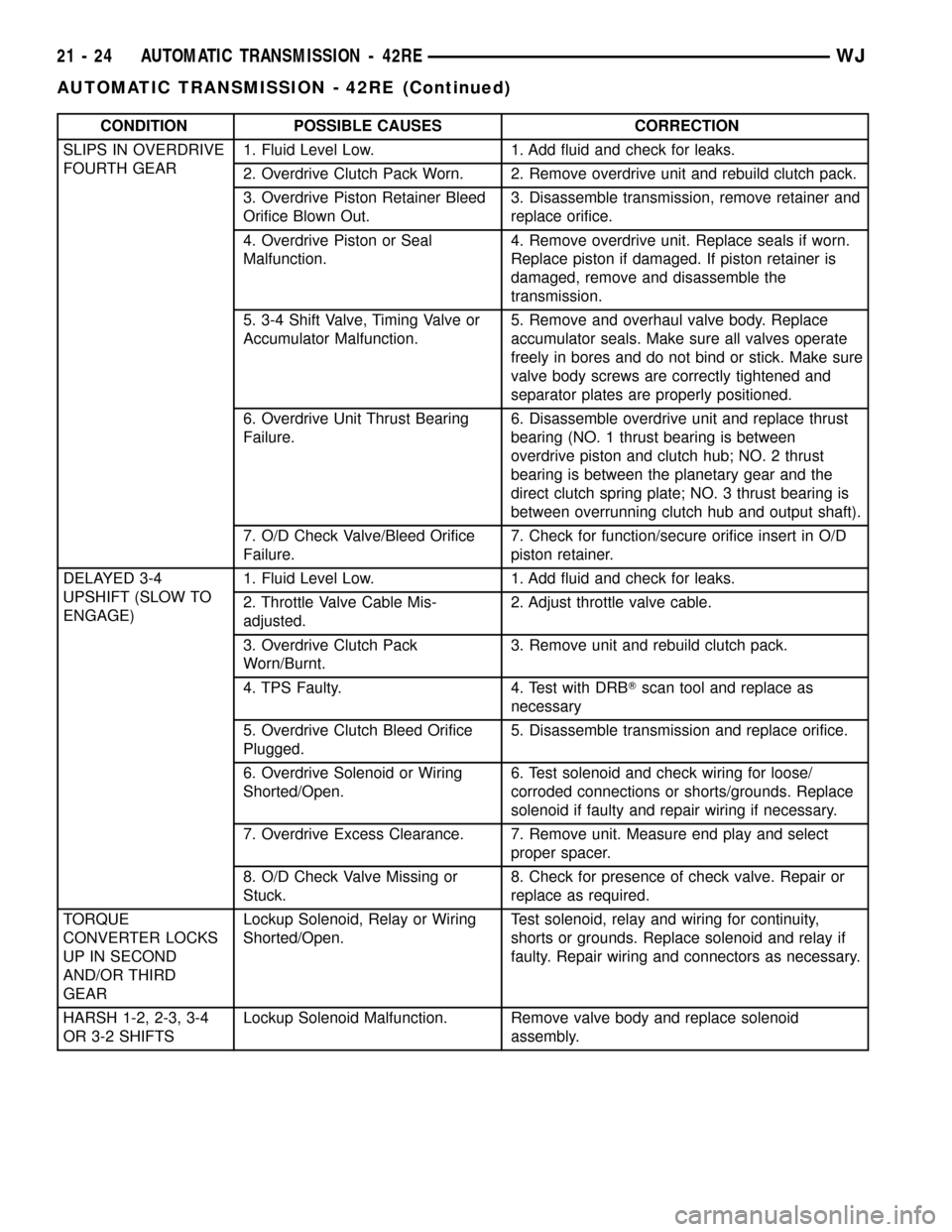
FOURTH GEAR1. Fluid Level Low. 1. Add fluid and check for leaks.
2. Overdrive Clutch Pack Worn. 2. Remove overdrive unit and rebuild clutch pack.
3. Overdrive Piston Retainer Bleed
Orifice Blown Out.3. Disassemble transmission, remove retainer and
replace orifice.
4. Overdrive Piston or Seal
Malfunction.4. Remove overdrive unit. Replace seals if worn.
Replace piston if damaged. If piston retainer is
damaged, remove and disassemble the
transmission.
5. 3-4 Shift Valve, Timing Valve or
Accumulator Malfunction.5. Remove and overhaul valve body. Replace
accumulator seals. Make sure all valves operate
freely in bores and do not bind or stick. Make sure
valve body screws are correctly tightened and
separator plates are properly positioned.
6. Overdrive Unit Thrust Bearing
Failure.6. Disassemble overdrive unit and replace thrust
bearing (NO. 1 thrust bearing is between
overdrive piston and clutch hub; NO. 2 thrust
bearing is between the planetary gear and the
direct clutch spring plate; NO. 3 thrust bearing is
between overrunning clutch hub and output shaft).
7. O/D Check Valve/Bleed Orifice
Failure.7. Check for function/secure orifice insert in O/D
piston retainer.
DELAYED 3-4
UPSHIFT (SLOW TO
ENGAGE)1. Fluid Level Low. 1. Add fluid and check for leaks.
2. Throttle Valve Cable Mis-
adjusted.2. Adjust throttle valve cable.
3. Overdrive Clutch Pack
Worn/Burnt.3. Remove unit and rebuild clutch pack.
4. TPS Faulty. 4. Test with DRBTscan tool and replace as
necessary
5. Overdrive Clutch Bleed Orifice
Plugged.5. Disassemble transmission and replace orifice.
6. Overdrive Solenoid or Wiring
Shorted/Open.6. Test solenoid and check wiring for loose/
corroded connections or shorts/grounds. Replace
solenoid if faulty and repair wiring if necessary.
7. Overdrive Excess Clearance. 7. Remove unit. Measure end play and select
proper spacer.
8. O/D Check Valve Missing or
Stuck.8. Check for presence of check valve. Repair or
replace as required.
TORQUE
CONVERTER LOCKS
UP IN SECOND
AND/OR THIRD
GEARLockup Solenoid, Relay or Wiring
Shorted/Open.Test solenoid, relay and wiring for continuity,
shorts or grounds. Replace solenoid and relay if
faulty. Repair wiring and connectors as necessary.
HARSH 1-2, 2-3, 3-4
OR 3-2 SHIFTSLockup Solenoid Malfunction. Remove valve body and replace solenoid
assembly.
21 - 24 AUTOMATIC TRANSMISSION - 42REWJ
AUTOMATIC TRANSMISSION - 42RE (Continued)
Page 2088 of 2199

LOCATING VACUUM LEAKS
WARNING: ON VEHICLES EQUIPPED WITH AIR-
BAGS, DISABLE THE AIRBAG SYSTEM BEFORE
ATTEMPTING ANY STEERING WHEEL, STEERING
COLUMN, OR INSTRUMENT PANEL COMPONENT
DIAGNOSIS OR SERVICE. DISCONNECT AND ISO-
LATE THE BATTERY NEGATIVE (GROUND) CABLE,
THEN WAIT TWO MINUTES FOR THE AIRBAG SYS-
TEM CAPACITOR TO DISCHARGE BEFORE PER-
FORMING FURTHER DIAGNOSIS OR SERVICE. THIS
IS THE ONLY SURE WAY TO DISABLE THE AIRBAG
SYSTEM. FAILURE TO TAKE THE PROPER PRE-
CAUTIONS COULD RESULT IN AN ACCIDENTAL
AIRBAG DEPLOYMENT AND POSSIBLE PERSONAL
INJURY.
(1) Disconnect the vacuum harness connector from
the back of the A/C Heater mode control switch on
the control panel.
(2) Connect the test set vacuum hose probe to each
port in the vacuum harness connector, one at a time,
and pause after each connection (Fig. 2). The test set
gauge should return to the 27 kPa (8 in. Hg.) setting
shortly after each connection is made. If OK, replace
the faulty mode control switch. If not OK, go to Step
3.(3) Determine the vacuum line color of the vacuum
circuit that is leaking. To determine the vacuum line
colors, refer to the Vacuum Circuits chart (Fig. 3).
(4) Disconnect and plug the vacuum line from the
component (fitting, actuator, valve, switch, or reser-
voir) on the other end of the leaking circuit. Instru-
ment panel disassembly or removal may be necessary
to gain access to some components.
(5) Connect the test set hose or probe to the open
end of the leaking circuit. The test set gauge should
return to the 27 kPa (8 in. Hg.) setting shortly after
each connection is made. If OK, replace the faulty
disconnected component. If not OK, go to Step 6.
(6) To locate a leak in a vacuum line, leave one
end of the line plugged and connect the test set hose
or probe to the other end. Run your fingers slowly
along the line while watching the test set gauge. The
vacuum reading will fluctuate when your fingers con-
tact the source of the leak. To repair the vacuum
line, cut out the leaking section of the line. Then,
insert the loose ends of the line into a suitable length
of 3 millimeter (1/8-inch) inside diameter rubber
hose.
Fig. 2 VACUUM CIRCUIT TEST
WJCONTROLS 24 - 11
CONTROLS (Continued)
Page 2095 of 2199

Both the manual A/C Heater control panel and the
AZC control panel are serviced only as complete
units and cannot be repaired. If faulty or damaged,
the entire control panel unit must be replaced.
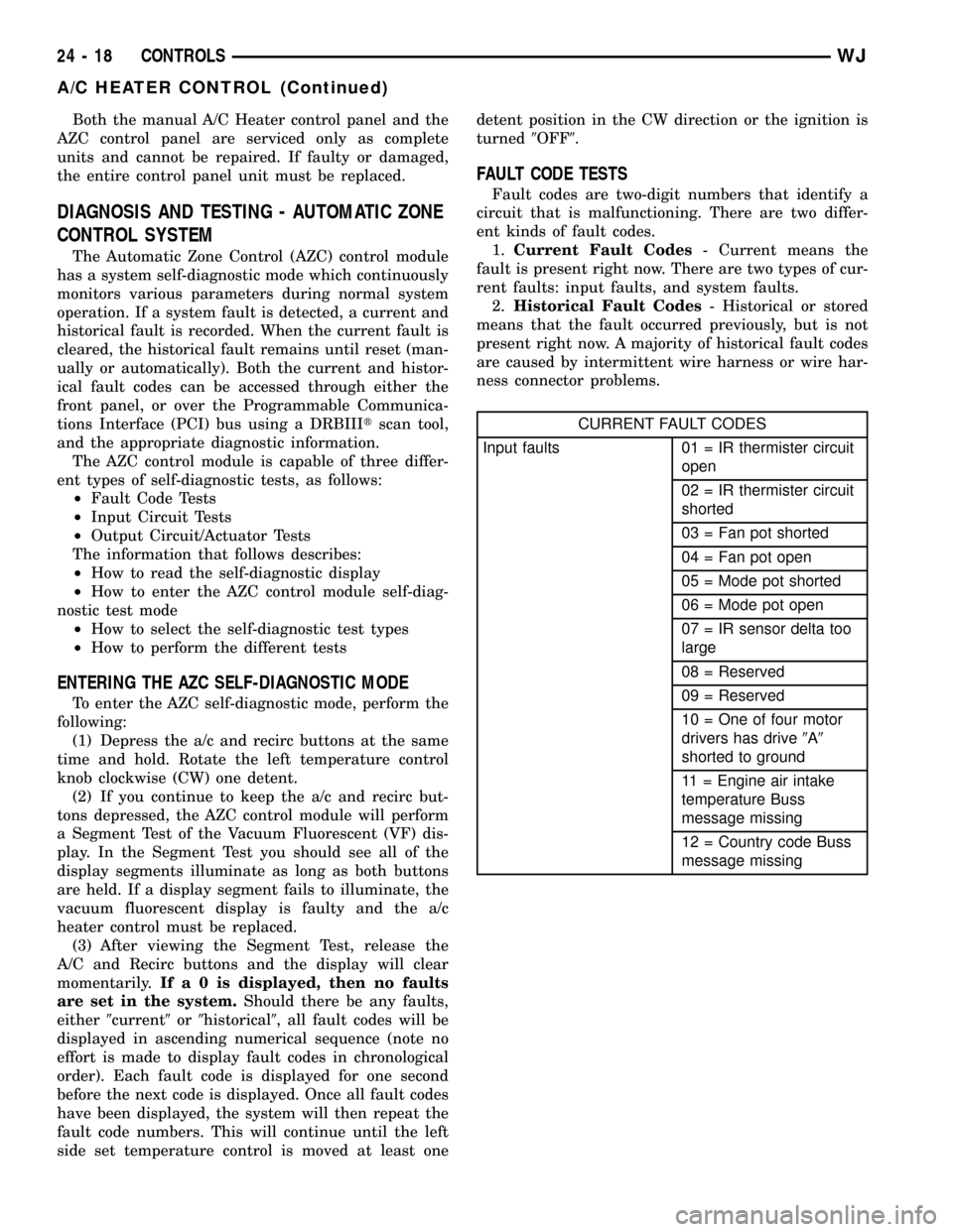
DIAGNOSIS AND TESTING - AUTOMATIC ZONE
CONTROL SYSTEM
The Automatic Zone Control (AZC) control module
has a system self-diagnostic mode which continuously
monitors various parameters during normal system
operation. If a system fault is detected, a current and
historical fault is recorded. When the current fault is
cleared, the historical fault remains until reset (man-
ually or automatically). Both the current and histor-
ical fault codes can be accessed through either the
front panel, or over the Programmable Communica-
tions Interface (PCI) bus using a DRBIIItscan tool,
and the appropriate diagnostic information.
The AZC control module is capable of three differ-
ent types of self-diagnostic tests, as follows:
²Fault Code Tests
²Input Circuit Tests
²Output Circuit/Actuator Tests
The information that follows describes:
²How to read the self-diagnostic display
²How to enter the AZC control module self-diag-
nostic test mode
²How to select the self-diagnostic test types
²How to perform the different tests
ENTERING THE AZC SELF-DIAGNOSTIC MODE
To enter the AZC self-diagnostic mode, perform the
following:
(1) Depress the a/c and recirc buttons at the same
time and hold. Rotate the left temperature control
knob clockwise (CW) one detent.
(2) If you continue to keep the a/c and recirc but-
tons depressed, the AZC control module will perform
a Segment Test of the Vacuum Fluorescent (VF) dis-
play. In the Segment Test you should see all of the
display segments illuminate as long as both buttons
are held. If a display segment fails to illuminate, the
vacuum fluorescent display is faulty and the a/c
heater control must be replaced.
(3) After viewing the Segment Test, release the
A/C and Recirc buttons and the display will clear
momentarily.Ifa0isdisplayed, then no faults
are set in the system.Should there be any faults,
either9current9or9historical9, all fault codes will be
displayed in ascending numerical sequence (note no
effort is made to display fault codes in chronological
order). Each fault code is displayed for one second
before the next code is displayed. Once all fault codes
have been displayed, the system will then repeat the
fault code numbers. This will continue until the left
side set temperature control is moved at least onedetent position in the CW direction or the ignition is
turned9OFF9.
FAULT CODE TESTS
Fault codes are two-digit numbers that identify a
circuit that is malfunctioning. There are two differ-
ent kinds of fault codes.
1.Current Fault Codes- Current means the
fault is present right now. There are two types of cur-
rent faults: input faults, and system faults.
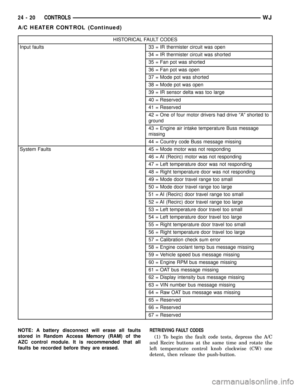
2.Historical Fault Codes- Historical or stored
means that the fault occurred previously, but is not
present right now. A majority of historical fault codes
are caused by intermittent wire harness or wire har-
ness connector problems.
CURRENT FAULT CODES
Input faults 01 = IR thermister circuit
open
02 = IR thermister circuit
shorted
03 = Fan pot shorted
04 = Fan pot open
05 = Mode pot shorted
06 = Mode pot open
07 = IR sensor delta too
large
08 = Reserved
09 = Reserved
10 = One of four motor
drivers has drive9A9
shorted to ground
11 = Engine air intake
temperature Buss
message missing
12 = Country code Buss
message missing
24 - 18 CONTROLSWJ
A/C HEATER CONTROL (Continued)
Page 2097 of 2199

HISTORICAL FAULT CODES
Input faults 33 = IR thermister circuit was open
34 = IR thermister circuit was shorted
35 = Fan pot was shorted
36 = Fan pot was open
37 = Mode pot was shorted
38 = Mode pot was open
39 = IR sensor delta was too large
40 = Reserved
41 = Reserved
42 = One of four motor drivers had drive9A9shorted to
ground
43 = Engine air intake temperature Buss message
missing
44 = Country code Buss message missing
System Faults 45 = Mode motor was not responding
46 = AI (Recirc) motor was not responding
47 = Left temperature door was not responding
48 = Right temperature door was not responding
49 = Mode door travel range too small
50 = Mode door travel range too large
51 = AI (Recirc) door travel range too small
52 = AI (Recirc) door travel range too large
53 = Left temperature door travel too small
54 = Left temperature door travel too large
55 = Right temperature door travel too small
56 = Right temperature door travel too large
57 = Calibration check sum error
58 = Engine coolant temp bus message missing
59 = Vehicle speed bus message missing
60 = Engine RPM bus message missing
61 = OAT bus message missing
62 = Display intensity bus message missing
63 = VIN number bus message missing
64 = Raw OAT bus message was missing
65 = Reserved
66 = Reserved
67 = Reserved
NOTE: A battery disconnect will erase all faults
stored in Random Access Memory (RAM) of the
AZC control module. It is recommended that all
faults be recorded before they are erased.RETRIEVING FAULT CODES
(1) To begin the fault code tests, depress the A/C
and Recirc buttons at the same time and rotate the
left temperature control knob clockwise (CW) one
detent, then release the push-button.
24 - 20 CONTROLSWJ
A/C HEATER CONTROL (Continued)