2003 JEEP GRAND CHEROKEE Rear arm
[x] Cancel search: Rear armPage 1899 of 2199

REMOVAL±REAR DOOR
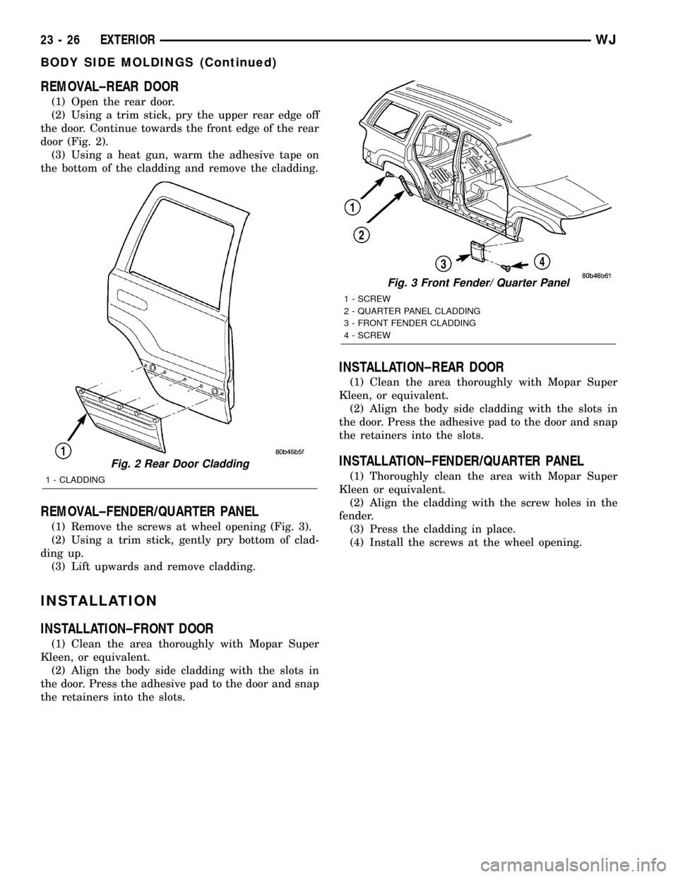
(1) Open the rear door.
(2) Using a trim stick, pry the upper rear edge off
the door. Continue towards the front edge of the rear
door (Fig. 2).
(3) Using a heat gun, warm the adhesive tape on
the bottom of the cladding and remove the cladding.
REMOVAL±FENDER/QUARTER PANEL
(1) Remove the screws at wheel opening (Fig. 3).
(2) Using a trim stick, gently pry bottom of clad-
ding up.
(3) Lift upwards and remove cladding.
INSTALLATION
INSTALLATION±FRONT DOOR
(1) Clean the area thoroughly with Mopar Super
Kleen, or equivalent.
(2) Align the body side cladding with the slots in
the door. Press the adhesive pad to the door and snap
the retainers into the slots.
INSTALLATION±REAR DOOR
(1) Clean the area thoroughly with Mopar Super
Kleen, or equivalent.
(2) Align the body side cladding with the slots in
the door. Press the adhesive pad to the door and snap
the retainers into the slots.
INSTALLATION±FENDER/QUARTER PANEL
(1) Thoroughly clean the area with Mopar Super
Kleen or equivalent.
(2) Align the cladding with the screw holes in the
fender.
(3) Press the cladding in place.
(4) Install the screws at the wheel opening.
Fig. 2 Rear Door Cladding
1 - CLADDING
Fig. 3 Front Fender/ Quarter Panel
1 - SCREW
2 - QUARTER PANEL CLADDING
3 - FRONT FENDER CLADDING
4 - SCREW
23 - 26 EXTERIORWJ
BODY SIDE MOLDINGS (Continued)
Page 1901 of 2199

EXTERIOR NAME PLATES
REMOVAL
NOTE: Exterior nameplates are attached to body
panels with adhesive tape.
(1) Apply a length of masking tape on the body,
parallel to the top edge of the nameplate to use as a
guide, if necessary.
(2) If temperature is below 21ÉC (70ÉF) warm
emblem with a heat lamp or gun. Do not exceed 52ÉC
(120ÉF) when heating emblem.
(3) Insert a plastic trim stick or a hard wood
wedge behind the emblem to separate the adhesive
backing from the body.
(4) Clean adhesive residue from body with MOPAR
Super Clean solvent or equivalent.
INSTALLATION
(1) Remove protective cover from adhesive tape on
back of emblem.
(2) Position emblem properly on body.(3) Press emblem firmly to body with palm of
hand.
(4) If temperature is below 21ÉC (70ÉF) warm
emblem with a heat lamp or gun to assure adhesion.
Do not exceed 52ÉC (120ÉF) when heating emblem.
FRONT FENDER
REMOVAL
(1) Using a wax crayon or equivalent, mark posi-
tion of fender.
(2) Remove front fender liner.
(3) Pull back fascia and remove screws attaching
fender to fascia.
(4) Remove screws attaching lower fender bracket
located behind fascia.
(5) Remove screws attaching fender to rocker
panel (Fig. 6).
(6) Remove screws attaching rear of fender to
A-pillar brackets.
(7) Open hood.
Fig. 6 Fender Mounting
1 - BODY
2 - FENDER
23 - 28 EXTERIORWJ
Page 1919 of 2199

GLOVE BOX
STANDARD PROCEDURE - GLOVE BOX ROLL
DOWN
WARNING: ON VEHICLES EQUIPPED WITH AIR-
BAGS, DISABLE THE AIRBAG SYSTEM BEFORE
ATTEMPTING ANY STEERING WHEEL, STEERING
COLUMN, OR INSTRUMENT PANEL COMPONENT
DIAGNOSIS OR SERVICE. DISCONNECT AND ISO-
LATE THE BATTERY NEGATIVE (GROUND) CABLE,
THEN WAIT TWO MINUTES FOR THE AIRBAG SYS-
TEM CAPACITOR TO DISCHARGE BEFORE PER-
FORMING FURTHER DIAGNOSIS OR SERVICE. THIS
IS THE ONLY SURE WAY TO DISABLE THE AIRBAG
SYSTEM. FAILURE TO TAKE THE PROPER PRE-
CAUTIONS COULD RESULT IN ACCIDENTAL AIR-
BAG DEPLOYMENT AND POSSIBLE PERSONAL
INJURY.
(1) Disconnect and isolate the battery negative
cable.
(2) Open the glove box until the integral stops on
the back edge of the glove box bin are resting against
the rubber stop bumpers in the upper glove box open-
ing reinforcement.
(3) Using hand pressure, lift upward on the arm of
the pneumatic glove box door damper on the out-
board side of the glove box bin to unsnap the damper
connector feature from the keyed slot in the bin (Fig.
16).(4) Reach into the glove box and with the middle
finger of each hand, deflect the rubber flap of the two
glove box stop bumpers on the upper glove box open-
ing reinforcement toward the front of the vehicle.
(5) With the glove box stop bumpers deflected, roll
the glove box door downward until the integral stops
on the back edge of the glove box bin pass through
the rubber stop bumper openings in the upper glove
box opening reinforcement (Fig. 17)
(6) Before rolling the glove box back up into the
instrument panel, grasp the pneumatic glove box
damper arm and pull the connector feature rearward
to the end of its travel. The rubber stop bumpers will
be deflected automatically by the integral stops on
the back of the glove box when the glove box is rolled
back up into the instrument panel.
(7) With the glove box stops oriented behind the
stop bumpers, position the connector feature of the
damper to the keyed slot on the outboard end of the
glove box bin.
(8) Using hand pressure, press downward on the
damper arm until the damper connector feature
snaps back into the keyed slot.
Fig. 16 Glove Box Damper
1 - BIN
2 - DAMPER
3 - CONNECTOR
4 - GLOVE BOX DOOR
Fig. 17 Glove Box Roll Down
1 - GLOVE BOX DOOR
23 - 46 INSTRUMENT PANEL SYSTEMWJ
Page 1953 of 2199

INSTALLATION
(1) Position the bin hooks high in the slots on the
quarter trim panel.
(2) Push downward until the bin snaps into place.
(3) Install the hinge screws.
REAR VIEW MIRROR
REMOVAL
(1)If equipped, disconnect mirror harness connector.
(2) Loosen the mirror base setscrew (Fig. 14).
(3) Slide the mirror base upward and off the
bracket.
INSTALLATION
INSTALLATION
(1) Position the mirror base at the bracket and
slide it downward onto the support bracket (Fig. 14).
(2) Tighten the setscrew 1 N´m (15 in. lbs.) torque.
(3) If equipped, connect mirror harness connector.
INSTALLATION - REARVIEW MIRROR
SUPPORT BRACKET
(1) Mark the position for the mirror bracket on the
outside of the windshield glass with a wax pencil.
(2) Clean the bracket contact area on the glass.
Use a mild powdered cleanser on a cloth saturated
with isopropyl (rubbing) alcohol. Finally, clean the
glass with a paper towel dampened with alcohol.
(3) Sand the surface on the support bracket with
fine grit-sandpaper. Wipe the bracket surface clean
with a paper towel.(4) Apply accelerator to the surface on the bracket
according to the following instructions:
(a) Crush the vial to saturate the felt applicator.
(b) Remove the paper sleeve.
(c) Apply accelerator to the contact surface on
the bracket.
(d) Allow the accelerator to dry for five minutes.
(e) Do not touch the bracket contact surface
after the accelerator has been applied.
(5)
Apply adhesive accelerator to the bracket contact
surface on the windshield glass. Allow the accelerator to
dry for one minute. Do not touch the glass contact sur-
face after the accelerator has been applied.
(6) Install the bracket according to the following
instructions:
(a)
Apply one drop of adhesive at the center of the
bracket contact-surface on the windshield glass.
(b) Apply an even coat of adhesive to the contact
surface on the bracket.
(c) Align the bracket with the marked position
on the windshield glass.
(d) Press and hold the bracket in place for at
least one minute.
NOTE: Verify that the mirror support bracket is cor-
rectly aligned, because the adhesive will cure rap-
idly.
(7) Allow the adhesive to cure for 8-10 minutes.
Remove any excess adhesive with an alcohol-damp-
ened cloth.
(8) Allow the adhesive to cure for an additional
8-10 minutes before installing the mirror.
SUN VISOR
REMOVAL
(1) Remove screws attaching sunvisor arm support
bracket to headliner and roof panel.
(2) Disengage electrical connections for vanity mir-
ror, if equipped.
(3) Detach sunvisor from support bracket.
(4) Remove sunvisor from vehicle.
(5) Remove retaining screw and support bracket.
INSTALLATION
(1) Install the retaining screw and support
bracket.
(2) Position the sunvisor in the vehicle.
(3) Connect the electrical harness for the lighted
vanity mirror, if equipped.
(4) Attach the sunvisor to the support bracket.
(5) Install the support bracket w/sunvisor onto the
headliner and roof panel.
Fig. 14 Rear View Mirror
1 - CONNECTOR
2 - SCREW
3 - REAR VIEW MIRROR
4 - SUPPORT BUTTON
5 - WINDSHIELD
23 - 80 INTERIORWJ
REAR STORAGE BOX (Continued)
Page 2026 of 2199

WELD LOCATIONS
SPECIFICATIONS
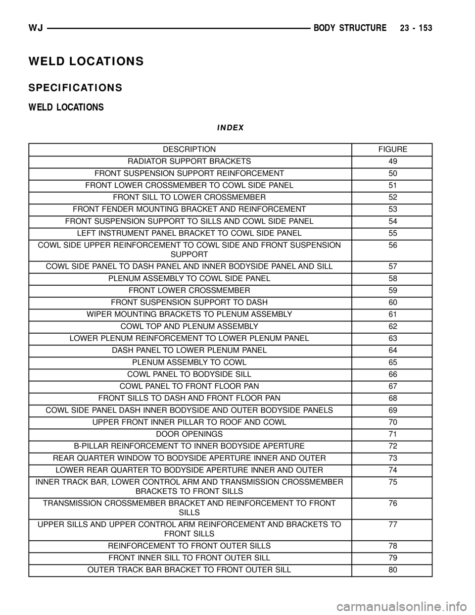
WELD LOCATIONS
INDEX
DESCRIPTION FIGURE
RADIATOR SUPPORT BRACKETS 49
FRONT SUSPENSION SUPPORT REINFORCEMENT 50
FRONT LOWER CROSSMEMBER TO COWL SIDE PANEL 51
FRONT SILL TO LOWER CROSSMEMBER 52
FRONT FENDER MOUNTING BRACKET AND REINFORCEMENT 53
FRONT SUSPENSION SUPPORT TO SILLS AND COWL SIDE PANEL 54
LEFT INSTRUMENT PANEL BRACKET TO COWL SIDE PANEL 55
COWL SIDE UPPER REINFORCEMENT TO COWL SIDE AND FRONT SUSPENSION
SUPPORT56
COWL SIDE PANEL TO DASH PANEL AND INNER BODYSIDE PANEL AND SILL 57
PLENUM ASSEMBLY TO COWL SIDE PANEL 58
FRONT LOWER CROSSMEMBER 59
FRONT SUSPENSION SUPPORT TO DASH 60
WIPER MOUNTING BRACKETS TO PLENUM ASSEMBLY 61
COWL TOP AND PLENUM ASSEMBLY 62
LOWER PLENUM REINFORCEMENT TO LOWER PLENUM PANEL 63
DASH PANEL TO LOWER PLENUM PANEL 64
PLENUM ASSEMBLY TO COWL 65
COWL PANEL TO BODYSIDE SILL 66
COWL PANEL TO FRONT FLOOR PAN 67
FRONT SILLS TO DASH AND FRONT FLOOR PAN 68
COWL SIDE PANEL DASH INNER BODYSIDE AND OUTER BODYSIDE PANELS 69
UPPER FRONT INNER PILLAR TO ROOF AND COWL 70
DOOR OPENINGS 71
B-PILLAR REINFORCEMENT TO INNER BODYSIDE APERTURE 72
REAR QUARTER WINDOW TO BODYSIDE APERTURE INNER AND OUTER 73
LOWER REAR QUARTER TO BODYSIDE APERTURE INNER AND OUTER 74
INNER TRACK BAR, LOWER CONTROL ARM AND TRANSMISSION CROSSMEMBER
BRACKETS TO FRONT SILLS75
TRANSMISSION CROSSMEMBER BRACKET AND REINFORCEMENT TO FRONT
SILLS76
UPPER SILLS AND UPPER CONTROL ARM REINFORCEMENT AND BRACKETS TO
FRONT SILLS77
REINFORCEMENT TO FRONT OUTER SILLS 78
FRONT INNER SILL TO FRONT OUTER SILL 79
OUTER TRACK BAR BRACKET TO FRONT OUTER SILL 80
WJBODY STRUCTURE 23 - 153
Page 2027 of 2199

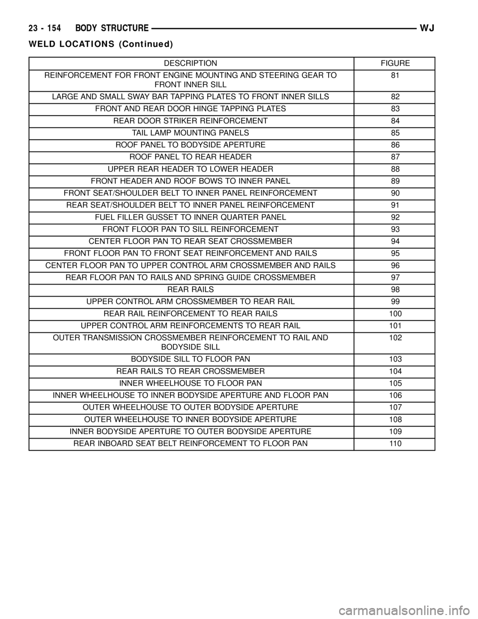
DESCRIPTION FIGURE
REINFORCEMENT FOR FRONT ENGINE MOUNTING AND STEERING GEAR TO
FRONT INNER SILL81
LARGE AND SMALL SWAY BAR TAPPING PLATES TO FRONT INNER SILLS 82
FRONT AND REAR DOOR HINGE TAPPING PLATES 83
REAR DOOR STRIKER REINFORCEMENT 84
TAIL LAMP MOUNTING PANELS 85
ROOF PANEL TO BODYSIDE APERTURE 86
ROOF PANEL TO REAR HEADER 87
UPPER REAR HEADER TO LOWER HEADER 88
FRONT HEADER AND ROOF BOWS TO INNER PANEL 89
FRONT SEAT/SHOULDER BELT TO INNER PANEL REINFORCEMENT 90
REAR SEAT/SHOULDER BELT TO INNER PANEL REINFORCEMENT 91
FUEL FILLER GUSSET TO INNER QUARTER PANEL 92
FRONT FLOOR PAN TO SILL REINFORCEMENT 93
CENTER FLOOR PAN TO REAR SEAT CROSSMEMBER 94
FRONT FLOOR PAN TO FRONT SEAT REINFORCEMENT AND RAILS 95
CENTER FLOOR PAN TO UPPER CONTROL ARM CROSSMEMBER AND RAILS 96
REAR FLOOR PAN TO RAILS AND SPRING GUIDE CROSSMEMBER 97
REAR RAILS 98
UPPER CONTROL ARM CROSSMEMBER TO REAR RAIL 99
REAR RAIL REINFORCEMENT TO REAR RAILS 100
UPPER CONTROL ARM REINFORCEMENTS TO REAR RAIL 101
OUTER TRANSMISSION CROSSMEMBER REINFORCEMENT TO RAIL AND
BODYSIDE SILL102
BODYSIDE SILL TO FLOOR PAN 103
REAR RAILS TO REAR CROSSMEMBER 104
INNER WHEELHOUSE TO FLOOR PAN 105
INNER WHEELHOUSE TO INNER BODYSIDE APERTURE AND FLOOR PAN 106
OUTER WHEELHOUSE TO OUTER BODYSIDE APERTURE 107
OUTER WHEELHOUSE TO INNER BODYSIDE APERTURE 108
INNER BODYSIDE APERTURE TO OUTER BODYSIDE APERTURE 109
REAR INBOARD SEAT BELT REINFORCEMENT TO FLOOR PAN 110
23 - 154 BODY STRUCTUREWJ
WELD LOCATIONS (Continued)
Page 2069 of 2199

Fig. 98 REAR RAILS
Fig. 99 UPPER CONTROL ARM CROSSMEMBER TO REAR RAIL
23 - 196 BODY STRUCTUREWJ
WELD LOCATIONS (Continued)
Page 2071 of 2199

Fig. 101 UPPER CONTROL ARM REINFORCEMENTS TO REAR RAIL
23 - 198 BODY STRUCTUREWJ
WELD LOCATIONS (Continued)