2003 Hyundai Matrix turn signal
[x] Cancel search: turn signalPage 208 of 312

1- 27
CONTROLS AND EQUIPMENT
B260A01FC-EAT INSTRUMENT CLUSTER AND INDICATOR (GASOLINE ENGINE) 1. Temperature Gauge
2. Tachometer
3. Speedometer
4. Digital Clock
5. Odometer/Trip Odometer/Trip Computer
(Not all models)
6. Fuel Gauge
7. Turn Signal Indicator Light
8. Automatic Transaxle Position Indicator Light (Auto T/A only)
9. Immobilizer Warning Indicator Light
10. SRS (Airbag) Warning Light
11. Traction Control Indicator Light (Not all models)
12. Overdrive off Indicator Light (Not all models)
13. Parking Brake/Brake Fluid Level Warning Light
14. Charging System Warning Light
15. Low Fuel Warning Light
16. High Beam Indicator Light
17. Tail Gate Open Warning Light
18. Door Ajar Warning Light
19. Oil Pressure Warning Light
20. Malfunction Indicator Light (MIL)
21. ABS Warning Light (Not all models)
B260A01FC-1
1
2 3
45
6
7 8 910
11 12 13 14 15 16 17 18
1920 21
7
Page 209 of 312

CONTROLS AND EQUIPMENT
1- 28
B260B01FC-EAT INSTRUMENT CLUSTER AND INDICATOR (DIESEL ENGINE) 1. Temperature Gauge
2. Tachometer
3. Speedometer
4. Digital Clock
5. Odometer/Trip Odometer/Trip Computer
(Not all models)
6. Fuel Gauge
7. Fuel Filter Warning Light
8. Turn Signal Indicator Light
9. Immobilizer Warning Indicator Light
10. SRS (Airbag) Warning Light
11. Diesel Pre-heat Indicator Light
12. Traction Control Indicator Light
(Not all models)
13. Parking Brake/Brake Fluid Level Warning Light
14. Charging System Warning Light
15. Low Fuel Warning Light
16. High Beam Indicator Light
17. Tail Gate Open Warning Light
18. Door Ajar Warning Light
19. Oil Pressure Warning Light
20. Malfunction Indicator Light (MIL)
21. ABS Warning Light (Not all models)
B260B01FC-1
1 23 4 5
6
7 8
910
8
11 12
1314
15 16 17 18
19 20 21
Page 210 of 312

1- 29
CONTROLS AND EQUIPMENTSB210E1-E OVERDRIVE OFF INDICATOR LIGHT (Not all models)
When the overdrive (4th gear) switch is turned off and the operation of overdrive (4th gear) iscancelled, the overdrive warning light (O/DOFF) will be illuminated. When the switch is atthe on position, the gearbox will operate in thenormal fully automatic mode and the warninglight will be extinguished.
B260P02Y-EAT
ABS SERVICE REMINDER INDICATOR (SRI)(Not all models)
When the key is turned to the "ON" position, the Anti-Lock Brake System SRI will come onand then go off in a few seconds. If the ABSSRI remains on, comes on while driving, ordoes not come on when the key is turned tothe "ON" position, this indicates that theremay be a problem with the ABS. If this occurs, have your vehicle checked by your Hyundai dealer as soon as possible. Thenormal braking system will still be operational,but without the assistance of the anti-lockbrake system.
CAUTION: If the both ABS SRI and Parking Brake/
Brake fluid level warning lights remain "ON" or come on while driving, there may be a
problem with E.B.D (Electronic Brake Force
Distribution).
If this occurs, avoid sudden stops and
have your vehicle checked by your Hyundaidealer as soon as possible. SB210K1-E
OIL PRESSURE WARNING LIGHT
CAUTION: If the oil pressure light illuminates when the engine is running, an insufficient oilpressure level for continued safe opera-tion of the engine exists. Continued opera-tion of the engine in this condition mayresult in serious engine damage. Under normal circumstances, the light will illuminate when the ignition is turned "on" andwill be extinguished when the engine is started. If the oil pressure warning light illuminates whilst the engine is running, stop the engineimmediately and check the engine oil level. Ifthe level is insufficient, add the required amountof oil as indicated by the engine oil dipstick. Ifthe light fails to extinguish when the engine isrestarted, do not continue to operate the ve-hicle. If the oil pressure light illuminates during nor- mal operation and the cause is not an insuffi-cient oil level, or the light fails to illuminatewhen the ignition is turned "on", contact thenearest Hyundai dealer before further operat-ing the vehicle.
SB210G1-E TURN SIGNAL INDICATOR LIGHT
Operation of a turn signal is indicated by the warning light located in the instrument cluster.If the light fails to illuminate or does not flash,a malfunction within the turn signal system isindicated.
SB210J1-E HIGH BEAM INDICATOR LIGHT
The high beam indicator light will illuminate
whenever the headlights are switched to high beam of flash position.
SB210C1-F
SRS (Airbag) SERVICE REMINDER INDICATOR
The SRS service reminder indicator (SRI) comes on and flashes for about 6 secondsafter the ignition key is turned to the "ON"position or after the engine is started, afterwhich it will go out. This light also comes on when the SRS is not working properly. If the SRI does not come on, or continuously remains on after flashing for about 6 secondswhen you turned the ignition key to the "ON"position or started the engine, or if it comes onwhile driving, have the SRS inspected by anauthorized Hyundai Dealer.
Page 216 of 312

1- 35
CONTROLS AND EQUIPMENTThe vehicle sidelights and headlights are op-
erated by rotating the end of the turn signal switch barrel. To operate the parking lights,rotating the switch to the first detent withignition switch at the "OFF" position will causethe lights to illuminate. To operate the head-lights, the turn signal switch barrel should berotated to the second detent. The headlightswill only operate when the ignition switch is atthe "On" position. If the ignition switch isturned to the "Off" position, only the parkinglights will function. Parking light auto cut (Not all models)
If you do not turn the parking lights "OFF"
after driving, the parking light will automati- cally shut "OFF" when the driver's door isopened.
To turn them "ON" again you must simply turn
the ignition key to the "ON" position.
B340C01FC-EAT LIGHTING SWITCH
SB220A1-E
MULTI FUNCTION SWITCH Turn Signal Operation
To signal an intention to turn right, the switch
lever should be pressed down. To signal an intention to turn left, the switch lever should bepushed upwards. In both instances, the turnsignal lights on one side of the car will flash andthe warning light located in the instrumentcluster will flash in sympathy. Upon completionof the manoeuvre, the lever will, under normalcircumstances, return to the "Off" position.However, if the manoeuvre involved only asmall movement of the steering wheel, thesignal may need to be cancelled manually. Ifeither turn signal indicator flashes more rapidlythan normal or refuses to flash at all, a mal-function of the turn signal system may exist. SB220B1-E Lane Change Signal To indicate an intention to change lanes, moving the lever slightly towards the directionof the relevant turn signal will cause the turnsignal lights to flash. When the lever is re-leased, it will return to the "off" position.
3. DRIVE TIME
Drive time symbol
Drive timeHFC2054
o This mode indicates the drive time trav- elled since the last drive time reset.
o Pressing the reset switch for more than 1 second, when the drive time is being dis- played, clears the drive time to zero. B340C01FC-D
B340B01FC-D
Page 217 of 312

CONTROLS AND EQUIPMENT
1- 36 The windscreen wiper switch, dependent upon
model, has three operating positions.
1. Intermittent wiper operation.
(Not all models)
2. Low speed operation.
3. High speed operation.
NOTE: To prevent damage to the wiper system,
do not attempt to wipe away heavy accu-mulations of snow or ice.
Accumulated snow and ice should be
removed manually. If there is only a lightlayer of snow or ice, operate the heater inthe defrost mode to melt the snow or icebefore using the wiper. SB230A1-E
WINDSCREEN WIPER/WASHER SWITCH
SB220E1-E HEADLIGHT FLASH The headlights may be flashed by pulling the turn signal switch lever towards the steeringwheel. The headlights will be extinguishedwhen the switch is released.
SB220D1-E HIGH AND LOW BEAM To turn on the headlight high beams, push the lever forward (away from you). For low beams,pull the lever back (toward you). The appropri-ate headlight beam indicator light will come onat the same time.
B340E01FC-D
B350A01O-D
(1)
(2)
(3)
B350B01O-EAT
Windscreen Washer Operation
To use the windscreen washer, pull the wiper/
washer lever toward the steering wheel. When the washer lever is operated, the wipers auto-matically make two passes across thewindscreen. The washer continues to operateuntil the lever is released.
NOTE:
o Do not operate the washer more than 15 seconds at a time or when the fluidreservoir is empty.
o In icy or freezing weather, be sure the wiper blades are not frozen to the glassprior to operating the wipers.
o In areas where water freezes in winter, use windscreen washer antifreeze. B350B01O-DAG
Page 218 of 312

1- 37
CONTROLS AND EQUIPMENTSB240A1-E
HAZARD WARNING SYSTEM
The hazard warning system should be used
whenever it becomes necessary to stop the car in a hazardous location. The hazard warn-ing system is operated by depressing theswitch at which time all turn signal lights willflash simultaneously and the turn signal warn-ing lights located within the instrument clusterwill flash simultaneously.
The hazard warning system may be turned off
by depressing the switch again.
B350C01FC-DAT Adjustable Intermittent Wiper Operation To use the intermittent wiper feature, place
the wiper switch in the "INT" position. With the switch in this position, the interval betweenwipes can be varied from approximately 1 to18 seconds by turning the interval adjusterbarrel.
Mist Wiper Operation If a single wipe is desired in mist, push the windscreen wiper and washer control leverupwards. B350A01O-AAT
Tail Gate Wiper And Washer Switch
1. :The washer fluid will be sprayed onto
the rear window and the wiper oper- ates while the rear window wiper barrelis placed in this position.
2.OFF
3.INT :To use the intermittent wiper feature, place the rear window wiper barrel in the "INT" position.
4.ON :When the point indicates "ON", the rear window wiper operates continu-ously.
B350B02O-DAG
B350C01O-DAG
B350D01O-DAG
HFC2078-D
Page 242 of 312

1- 61
CONTROLS AND EQUIPMENT
B870D01FC-GAT ANTENNA Roof Antenna
Your car uses a roof antenna to receive both AM and FM broadcast signals. This antenna is a removable type. To remove the antenna, turn the antenna counterclock-wise. To install the antenna, turn the antennaclockwise. CAUTION:
o Be sure to remove the antenna before washing the car in an automatic car wash or it may be damaged.
o Before entering a place with a low height clearance, be sure to adjust the roofantenna low.
o When reinstalling your antenna, it is important that it is fully tightened toensure proper reception.
HFC2100
Page 256 of 312
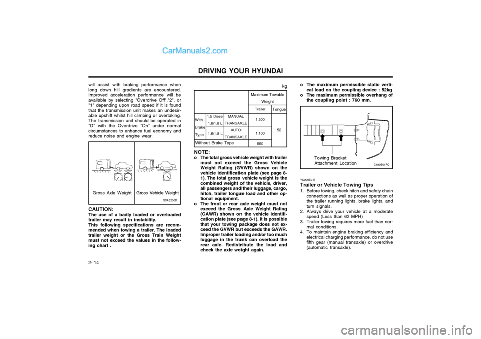
DRIVING YOUR HYUNDAI
2- 14 YC200E2-E Trailer or Vehicle Towing Tips
1. Before towing, check hitch and safety chain
connections as well as proper operation of the trailer running lights, brake lights, andturn signals.
2. Always drive your vehicle at a moderate speed (Less than 62 MPH)
3. Trailer towing requires more fuel than nor- mal conditions.
4. To maintain engine braking efficiency and electrical charging performance, do not usefifth gear (manual transaxle) or overdrive(automatic transaxle). Towing Bracket Attachment Location
NOTE:
o The total gross vehicle weight with trailer must not exceed the Gross Vehicle Weight Rating (GVWR) shown on thevehicle identification plate (see page 8-1). The total gross vehicle weight is thecombined weight of the vehicle, driver,all passengers and their luggage, cargo,hitch, trailer tongue load and other op-tional equipment.
o The front or rear axle weight must not exceed the Gross Axle Weight Rating(GAWR) shown on the vehicle identifi-cation plate (see page 8-1). it is possiblethat your towing package does not ex-ceed the GVWR but exceeds the GAWR.Improper trailer loading and/or too muchluggage in the trunk can overload therear axle. Redistribute the load andcheck the axle weight again. MANUAL
TRANSAXLE
AUTO
TRANSAXLE Trailer
1,300 1,100 550 Tongue
52
kg
Maximum Towable Weight
With BrakeType
1.5 Diesel 1.6/1.8 L
1.6/1.8 L
Without Brake Type
o The maximum permissible static verti- cal load on the coupling device : 52kg
o The maximum permissible overhang of the coupling point : 760 mm.
C190E01FC
will assist with braking performance when long down hill gradients are encountered.Improved acceleration performance will beavailable by selecting "Overdrive Off","2", or"1" depending upon road speed if it is foundthat the transmission unit makes an undesir-able upshift whilst hill climbing or overtaking.The transmission unit should be operated in"D" with the Overdrive "On" under normalcircumstances to enhance fuel economy andreduce noise and engine wear.
Gross Axle Weight
CAUTION: The use of a badly loaded or overloaded trailer may result in instability.This following specifications are recom-mended when towing a trailer. The loadedtrailer weight or the Gross Train Weightmust not exceed the values in the follow-ing chart . SSA2200DGross Vehicle Weight