2003 Hyundai Grandeur warning lights
[x] Cancel search: warning lightsPage 81 of 235

FEATURES OF YOUR HYUNDAI 1- 67
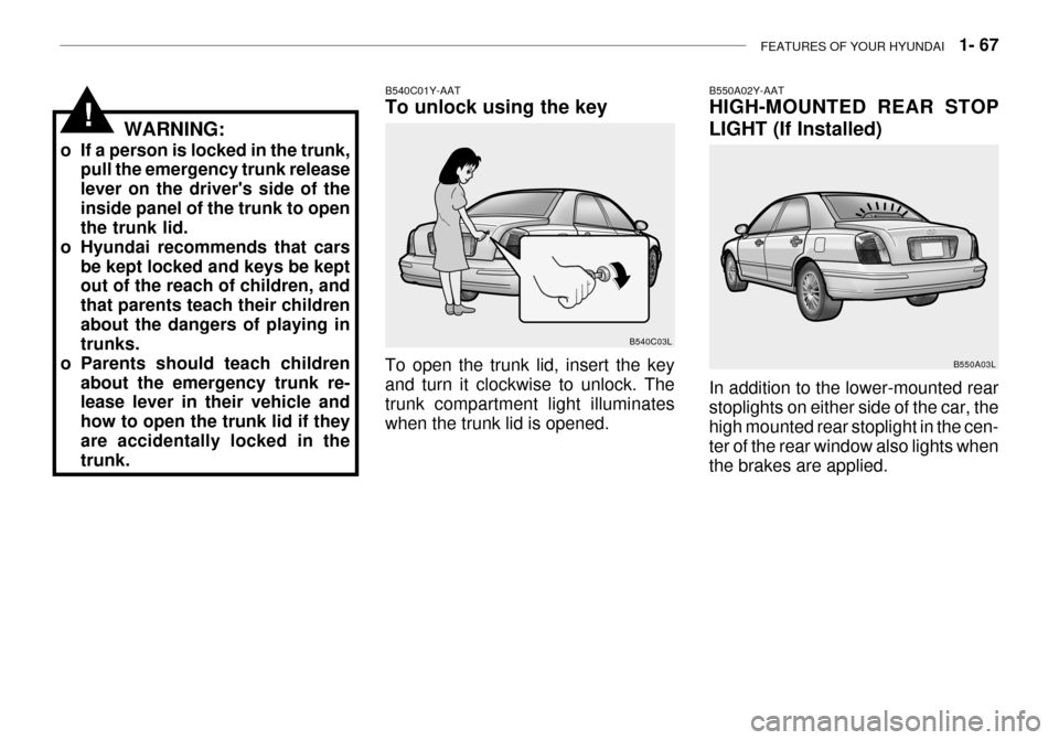
B550A02Y-AAT HIGH-MOUNTED REAR STOP
LIGHT (If Installed) In addition to the lower-mounted rear stoplights on either side of the car, thehigh mounted rear stoplight in the cen- ter of the rear window also lights when the brakes are applied. B550A03L
To open the trunk lid, insert the key and turn it clockwise to unlock. The trunk compartment light illuminates when the trunk lid is opened.
WARNING:
o If a person is locked in the trunk, pull the emergency trunk releaselever on the driver's side of theinside panel of the trunk to open the trunk lid.
o Hyundai recommends that cars be kept locked and keys be keptout of the reach of children, and that parents teach their childrenabout the dangers of playing in trunks.
o Parents should teach children about the emergency trunk re-lease lever in their vehicle and how to open the trunk lid if theyare accidentally locked in the trunk. B540C01Y-AAT To unlock using the key
B540C03L
!
Page 87 of 235

FEATURES OF YOUR HYUNDAI 1- 73
B600B01L-GAT STEERING WHEEL ELECTRIC TILT AND TELESCOPIC
(If Installed)
HXGS262
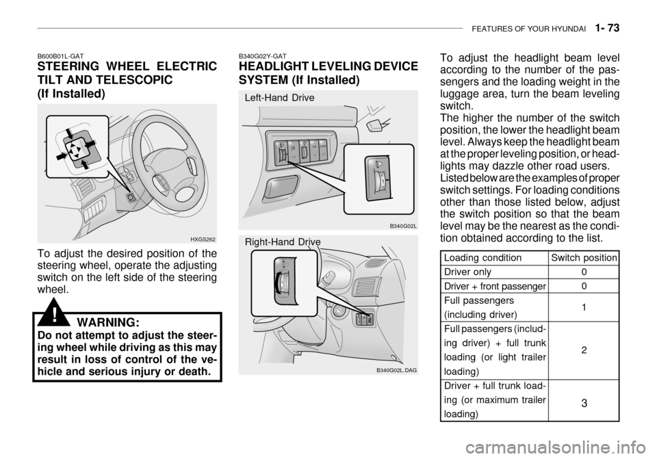
To adjust the desired position of the steering wheel, operate the adjusting switch on the left side of the steeringwheel.
WARNING:
Do not attempt to adjust the steer-ing wheel while driving as this mayresult in loss of control of the ve- hicle and serious injury or death.
!
Switch position
0 0 1 2
3Loading condition Driver only Driver + front passenger Full passengers(including driver) Full passengers (includ- ing driver) + full trunkloading (or light trailer loading)
Driver + full trunk load-ing (or maximum trailer
loading)
B340G02L
B340G02L.DAG
B340G02Y-GAT HEADLIGHT LEVELING DEVICE
SYSTEM (If Installed)
Left-Hand Drive Right-Hand Drive
To adjust the headlight beam level according to the number of the pas- sengers and the loading weight in theluggage area, turn the beam leveling switch. The higher the number of the switchposition, the lower the headlight beam level. Always keep the headlight beam at the proper leveling position, or head-lights may dazzle other road users. Listed below are the examples of proper switch settings. For loading conditionsother than those listed below, adjust the switch position so that the beam level may be the nearest as the condi-tion obtained according to the list.
Page 135 of 235

DRIVING YOUR HYUNDAI 2- 3
C020A01A-AAT BEFORE STARTING THE EN- GINE Before you start the engine, you should always:
1. Look around the vehicle to be sure
there are no flat tires, puddles of oil, water or other indications of pos-sible trouble.
2. After entering the car, check to be
sure the parking brake is engaged.
3. Check that all windows, and lights are clean.
4. Check that the interior and exterior mirrors are clean and in position.
5. Check your seat, seatback and
headrest to be sure they are in theirproper positions.
6. Lock all the doors.
7. Fasten your seat belt and be sure
that all other occupants have fas- tened theirs.
8. Turn off all lights and accessories
that are not needed.
9. When you turn the ignition switch to
"ON", check that all appropriate warning lights are operating and that you have sufficient fuel. C030A01A-GAT COMBINATION IGNITION SWITCHTo Start the Engine
o If your Hyundai is equipped with a
manual transaxle, place the shift lever in neutral and depress the clutch pedal fully.
o If your Hyundai has an automatic transaxle, place the shift lever in "P"(park).
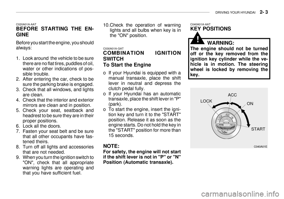
o To start the engine, insert the igni-
tion key and turn it to the "START"position. Release it as soon as the engine starts. Do not hold the key in the "START" position for more than15 seconds.
NOTE: For safety, the engine will not start if the shift lever is not in "P" or "N"Position (Automatic transaxle).
10.Check the operation of warning
lights and all bulbs when key is inthe "ON" position.C040A01A-AAT KEY POSITIONS
WARNING:
The engine should not be turned off or the key removed from the ignition key cylinder while the ve-hicle is in motion. The steering wheel is locked by removing the key.
C040A01E
LOCK
ACC
ON
START
!
Page 137 of 235

DRIVING YOUR HYUNDAI 2- 5
C050B01A-GAT Normal Conditions: The Starting Procedure:
1. Insert key, and fasten the seat belt.
2. Depress the clutch pedal fully and
place the gearshift lever (manual transaxle) in neutral or the selector lever (automatic transaxle) in "P" (park) position.
3. After turning the ignition key to the "ON" position, make certain all warn-ing lights and gauges are function-ing properly before starting the en- gine.
WARNING:
Be sure that the clutch is fully de- pressed when starting a manualtransaxle vehicle. Otherwise, there is the potential to cause damage to the vehicle or injury to someoneinside or outside the vehicle as a result of the forward or backward movement of the vehicle that willoccur if the clutch is not depressed when the vehicle is started. 4. Turn the ignition key to the "Start"
position and release it when the engine starts.
C070A02A-AAT OPERATING THE MANUAL TRANSAXLE
HFC3029
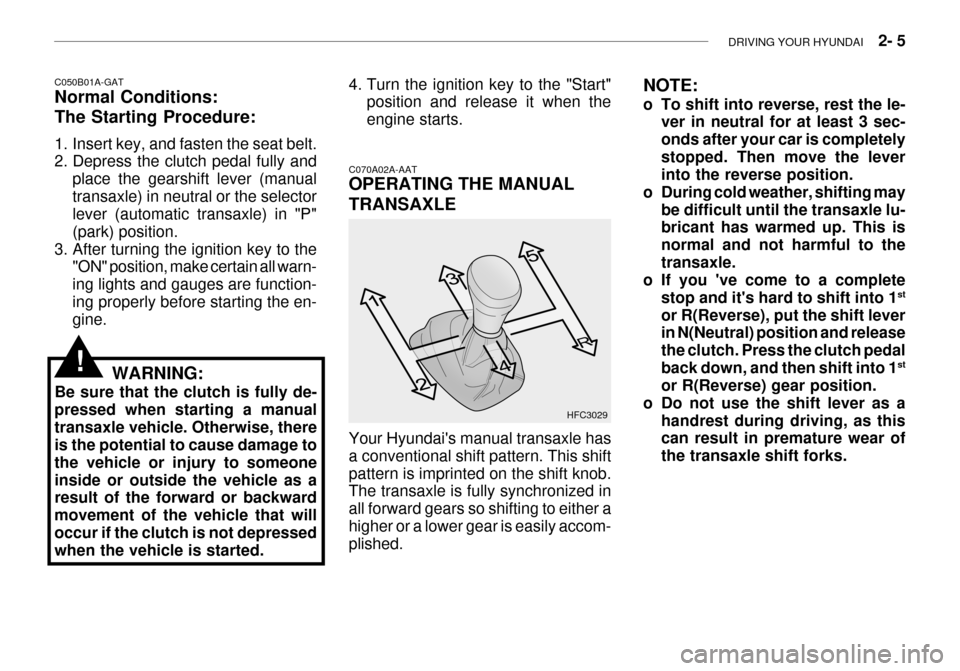
Your Hyundai's manual transaxle has a conventional shift pattern. This shiftpattern is imprinted on the shift knob. The transaxle is fully synchronized in all forward gears so shifting to either ahigher or a lower gear is easily accom- plished. NOTE:
o To shift into reverse, rest the le-
ver in neutral for at least 3 sec- onds after your car is completelystopped. Then move the lever into the reverse position.
o During cold weather, shifting may
be difficult until the transaxle lu-bricant has warmed up. This is normal and not harmful to thetransaxle.
o If you 've come to a complete
stop and it's hard to shift into 1 st
or R(Reverse), put the shift lever in N(Neutral) position and release the clutch. Press the clutch pedalback down, and then shift into 1 st
or R(Reverse) gear position.
o Do not use the shift lever as a
handrest during driving, as this can result in premature wear of the transaxle shift forks.
!
Page 157 of 235

WHAT TO DO IN AN EMERGENCY 3- 3
WARNING:
The gas produced by the battery during the jump-start operation is highly explosive. If these instruc- tions are not followed exactly, seri-ous personal injury and damage to the vehicle may occur! If you are not sure how to follow this proce-dure, seek qualified assistance. Automobile batteries contain sul- furic acid. This is poisonous andhighly corrosive. When jump start- ing, wear protective glasses and be careful not to get acid on yourself,your clothing or on the car.
o If you should accidentally get acid on your skin or in your eyes, imme- diately remove any contaminatedclothing and flush the area with clear water for at least 15 minutes. Then promptly obtain medical attention. Ifyou must be transported to an emer- gency facility, continue to apply water to the affected area with a spongeor cloth. o The gas produced by the battery
during the jump-start operation ishighly explosive. Do not smoke orallow a spark or open flame in the vicinity.
o The battery being used to provide the jump start must be 12-volt. If youcannot determine that it is a 12-volt battery, do not attempt to use it forthe jump start.
o To jump start a car with a discharged
battery, follow this procedure ex-actly:
1. If the booster battery is installed in another vehicle, be sure the two vehicles are not touching.
2. Turn off all unnecessary lights and accessories in both vehicles.
3. Attach the clamps of the jumper
cable in the exact order shown in the illustration. That is, first, attach one clamp of the jumper cable to the positive (+) post or cable of thedischarged battery. Then attach the other end of the same cable to the positive (+) post or cable of thebooster battery. Next, using the other cable, attach one clamp to the negative (-) post or cable of the booster battery. Then attach the other end of that cable to a solid metal part of the engine away fromthe battery. Do not connect the cable to any moving part.
4. Start the engine in the car with the booster battery and let it run for afew minutes. This will help to as- sure that the booster battery is fullycharged. During the jumping opera- tion, run the engine in this vehicle at about 2,000 rpm.
5. Start the engine in the car with the discharged battery using the nor-mal starting procedure. After theengine starts, leave the jumper cables connected and let the engine run at fast idle or about 2,000 rpmfor several minutes.
6. Carefully remove the jumper cables
in the reverse order of attachment.
If you do not know why your batterybecame discharged (because the lightswere left on, etc.), have the charging system checked by your Hyundai dealer.!
Page 216 of 235

DO-IT-YOURSELF MAINTENANCE 6- 35
FUSE RATING
25A 20A10A15A10A10A10A15A10A10A15A 10A 10A 10A20A10A 15A 10A15A10A10A15A10A20A 10A 10A 10A 10A10A10A 10A 10A PROTECTED COMPONENTS
Power seat
Seat warmerEPS controls
ETS relay
(HID) Head lights, DRL controls, AQS sensor
Blower & A/C controls
Turn & Hazard controlsNot used
Cruise switch, Instrument cluster
Head light leveling switch, Rain sensor, IMS controls
Rain sensor relay, Wiper & Washer controls
Home link connector, Left (Right) vanity lights, Sunroof, Blower & A/C controls,Electronic chrome mirrorNot used
Audio
Front (Rear) cigarette lighter, Accessory socket
IMS controls, Driver door module, RheostatNot used
Rear for light relay
Stop lights, Left (Right) personal lights, Left (Right) rear door lights
Door warning & Ignition key illumination, Courtesy lightsInstrument clusterSRS controls
Automatic transaxle controls, Back-up light switch, Vehicle speed sensor
Fuel filler door & Trunk lid opener, Driver (Assister) door module
Multipurpose check connector, Audio, lmmobiilizer controls, Trip computers, Digital
clock, Blower & A/C controls, Instrument cluster
Left (Right) inside lights, (HID) Head lights, Fog light relay, Right HID turn signal light,Right rear combination light
Stop light failure relay
Immobilizer controls, TCS switch, Trip computers, Instrument cluster
ETACM, Hazard switch, Auto light sensor
Antenna, Blower & A/C controls, Left (Right) outside mirror motor & Folding motor
(HID) Head lights, Front (Rear) cigarette lighters, Left (Right) license lights, Left HID
Turn signal light, Left rear combination lightBurglar alarm relay, Transaxle range switch, Start relay, ETS controlsDESCRIPTION
P/SEAT
S/HTR EPSETS
H/LP
A/CON SW HAZARDSPARE
CRUISE IMS
WIPER
ETACS
SPARE AUDIO
C/LIGHTER MIRRORSPARE
RR FOG
STOP LP
ROOM LP
A/BAG IND A/BAGB/UP
T/LID
D/CLOCK
RH TAILSPARE
CLUSTER T/SIG
RR HTD IND
LH TAIL
START
G200D01L-GAT
Instrument Panel Junction Box
G200D01L
Page 232 of 235

10- 4 INDEX
H
Hazard Warning System ........................................... 1-53
Headlight Aiming Adjustm ent .................................... 6-25
Headlight Leveling Device Syst em ...........................1-73
Heating and Ventilation ................................. 1-78 ~ 1-92
Air flow control ..................... 1-80 ~ 1-81, 1-89 ~ 1-91
Air intake control .................. 1-79 ~ 1-80, 1-88 ~ 1-89
Bi-level heating ....................................................... 1-82
Fan speed control ........................................ 1-79, 1-88Temperature control ............................................... 1-82
High-Mounted Rear Stop Light................................. 1-67
Hood Release ........................................................... 1-69
Horn .......................................................................... 1-72
IIgnition Switch ............................................................. 2-3
Illuminated Ignition Switch .................... ...................... 1-5
Immobilizer S ystem ........................................... 1-4 ~ 1-5
Instrument Cluster and Indicator Lights ....... 1-40 ~ 1-45
Instrument Panel Light Control (Rheost at)............... 1-56
Intergrated Memory System (I. M. S) .......... 1-16 ~ 1-17Interior Light Interior light ................................................ 1-61 ~ 1-62
Map light .................................................... 1-60 ~ 1-61
Personal light ......................................................... 1-62
Intermittent Wiper ..................................................... 1-52
J Jump Starting .................................................... 3-2 ~ 3-3 K
Key .................................................................... 1-3 ~ 1-4
If you lose your keys ............................................. 3-12
Positions ......................................................... 2-3 ~ 2-4
L Lubrication Chart ......................................................... 9-4
Luggage Net ............................................................. 1-70
MMaintenance Intervals Explanation of scheduled maintenance items
....................................................................... 5-7 ~ 5-9
Maintenance under severe usage conditions .......... 5-6Scheduled maintenance ................................. 5-4 ~ 5-5
Service require ments ............................................... 5-2
Mirrors Day-night inside rearvi ew .......................................1-64
Outside rearview mirror heater .............................. 1-63
O
Odometer ...................................................... 1-47 ~ 1-48
Outside rearview mirror ............................................ 1-63
PParking Brake ........................................................... 1-65
Passenger Presence Detec tion .............................. 1-36
Power Outle t ............................................................. 1-70
Power Seat ............................................................... 1-14
Page 234 of 235

10- 6 INDEX
V Vehicle Identification Number ..................................... 8-2
W Warning Lights .............................................. 1-42 ~ 1-45
Power Windows ............................................ 1-10 ~ 1-11
Windshield Wiper and Washer Switc h .....................1-51
Windshield Wiper Blades ..................... ..................... 6-12