Page 55 of 338
The seat belts in all seating positions
except the driver’s have an additional
locking mechanism that must be
activated to secure a child seat. (See
pages and f or instructions on
how to secure child seats with this
type of seat belt.)
If the shoulder part of the belt is
pulled all the way out, the locking
mechanism will activate. The belt
will retract, but it will not allow the
passenger to move f reely.
To deactivate the locking
mechanism, unlatch the buckle and
let the seat belt f ully retract. To
ref asten the belt, pull it out only as
f ar as needed.
See page f or instructions on how
to wear the lap/shoulder belt
properly.35
39
17
Additional Inf ormation About Your Seat Belts
Driver and Passenger Saf ety51
Page 67 of 338

This section gives inf ormation about
the controls and displays that
contribute to the daily operation of
your Honda. All the essential
controls are within easy reach............................
Control Locations .64
...............................
Indicator Lights .65
.............................................
Gauges .72
...............................
Speedometer .72 .................................
Tachometer .72
..............
Odometer/Trip Meter . 73
..................................
Fuel Gauge .73
...................
Temperature Gauge . 74
Controls Near the Steering .......................................
Wheel .75
...................................
Headlights .76
............
Daytime Running Lights . 77
....
Instrument Panel Brightness . 77
................................
Turn Signals .77
.....................
Windshield Wipers .78
..................
Windshield Washers . 79
Rear Window Wiper and .....................................
Washer .80
..........................
Hazard Warning .81
.............
Rear Window Def ogger . 81
......
Steering Wheel Adjustment . 82
...............................
Keys and Locks .83
..............................................
Keys .83
....................
Immobilizer System . 84
............................
Ignition Switch .85
......................
Power Door Locks .87
..................................
Rear Doors .88
............................................
Hatch .89
........................................
Tailgate .90
....................................
Glove Box .91 .................................................
Seats .92
.............
Front Seat Adjustments . 92
Driver’s Seat Height ..............................
Adjustment .93
................
Driver’s Seat Armrest . 93
..........................
Head Restraints .94
........................
Rear Seat Access .95
.......
Rear Seat-back Adjustment . 96
..........
Reclining the Front Seats . 97
...............
Folding the Rear Seats . 99
........
Removing the Rear Seats . 101
............................
Power Windows .103
...............................
Rear Windows .105
...........................................
Mirrors .106
..
Adjusting the Power Mirrors . 106
..........................................
Skylight .107
.........................
Beverage Holders .110
...............................
Parking Brake .111
...............................
Ceiling Pocket .112
.......................................
Coin Tray .112
............
Accessory Power Sockets . 113
...............................
Interior Lights .114
..............................
Ceiling Light .114
...................................
Spotlights .114
......................
Cargo Area Light .115
................
Ignition Switch Light . 115
Instruments and Controls
Inst rument s and Cont rols63
Page 68 of 338
Control L ocations
Inst rument s and Cont rols64
POWER DOOR LOCK SWITCHMIRROR CONTROLS AUDIO SYSTEM
PARKING BRAKE
A/T model is shown. HOOD RELEASE
HANDLE POWER WINDOW
SWITCHES
HEATING/COOLING
CONTROLS
(P.87)
(P.103)
(P.160)
(P.118)(P.126,
137)
(P.106)
(P.111)
Page 69 of 338
�Î
�Î
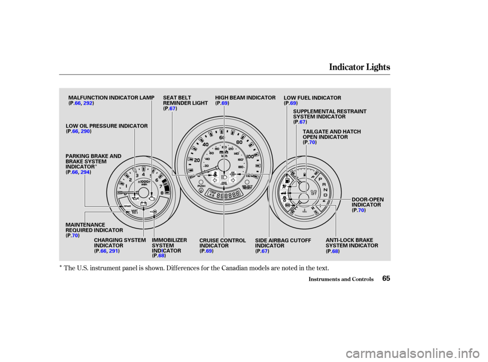
The U.S. instrument panel is shown. Dif f erences f or the Canadian models are noted in the text.
Indicator L ights
Inst rument s and Cont rols65
IMMOBILIZER
SYSTEM
INDICATOR
(P.68)
MAINTENANCE
REQUIRED INDICATOR
(P.70) (P.67)
DOOR-OPEN
INDICATOR
(P.70)
CRUISE CONTROL
INDICATOR (P. 69) SIDE AIRBAG CUTOFF
INDICATOR
(P.67)
LOW OIL PRESSURE INDICATOR
PARKING BRAKE AND
BRAKE SYSTEM
INDICATOR
CHARGING SYSTEM
INDICATOR
(P.66,
290)
(P.66, 291) (P.69) LOW FUEL INDICATOR
HIGH BEAM INDICATOR
SEAT BELT
REMINDER LIGHT
(P.67)TAILGATE AND HATCH
OPEN INDICATOR
(P.70)
SUPPLEMENTAL RESTRAINT
SYSTEM INDICATOR
(P.69)
MALFUNCTION INDICATOR LAMP
ANTI-LOCK BRAKE
SYSTEM INDICATOR
(P.68)
(P.66,
292)
(P.66, 294)
Page 72 of 338
. It will then go of f if
you have inserted a properly-coded
ignition key. If it is not a properly-
coded key, the")
This indicator comes on f or a f ew
seconds when you turn the ignition
switch ON (II). It will then go of f if
you have inserted a properly-coded
ignition key. If it is not a properly-
coded key, the indicator will blink
and the engine will not start (see
page ).
This indicator also blinks several
times when you turn the ignition
switch f rom ON (II) to ACCESSORY
(I) or LOCK (0).The lef t or right turn signal light
blinks when you signal a lane change
or turn. If the light does not blink or
blinks rapidly, it usually means one
of the turn signal bulbs is burned out
(see page ). Replace the bulb as
soon as possible, since other drivers
cannot see that you are signaling.
WhenyouturnontheHazard
Warning switch, both turn signal
lights blink. All turn signals on the
outside of the vehicle should f lash.
This light normally comes on f or a
f ew seconds when you turn the
ignition switch ON (II), and when
the ignition switch is turned to
START (III). If this light comes on at
any other time, there is a problem in
theABS.If thishappens,takethe
vehicle to your dealer to have it
checked. With the light on, your
vehicle still has normal braking
ability but no anti-lock. For complete
inf ormation, see page .
188 84
259
Only on models equipped with ABS (see
page ) 186
Immobilizer System
Indicator
Turn Signal and Hazard Warning
Indicators
Anti-lock Brake
System (A BS)
Indicator
Indicator L ights
Inst rument s and Cont rols68
Page 86 of 338
Push the lever up to lock the
steering wheel in that position.
Make sure you have securely
locked the steering wheel in place
by trying to move it up and down.
To adjust the steering wheel upward
or downward:
Make any steering wheel adjustment
bef ore you start driving.
Push the lever under the lef t side
of the steering column all the way
down.
Move the steering wheel to the
desired position, making sure the
wheel points toward your chest,
not toward your f ace. Make sure
you can see the instrument panel
gauges and the indicator lights.
1.
2. 3.
4.
See page f or important saf ety
inf ormation about how to properlyposition the steering wheel. 20
Steering Wheel A djustment
Controls Near the Steering Wheel
Inst rument s and Cont rols82
Adjusting the steering wheel
position while driving may
cause you to lose control of the
vehicle and be seriously injured
inacrash.
Adjust the steering wheel only
when the vehicle is stopped.
Page 87 of 338

These keys contain electronic
circuits that are activated by the
Immobilizer System. They will not
work to start the engine if the
circuits are damaged.Protect the keys f rom direct
sunlight, high temperature, and
high humidity.
The keys do not contain batteries.
Do not try to take them apart. Keep the keys away f rom liquids.
If they get wet, dry them
immediately with a sof t cloth. Donotdropthekeysorsetheavy
objects on them.
Your vehicle comes with two master
keys and a valet key. When replacing keys, use only
Honda-approved key blanks. The valet key works only in the
ignition and the door locks. You can
keep the glove box and hatch locked
when you leave your vehicle and the
valet key at a parking f acility.
Youshouldhavereceivedakey
number tag with your set of keys.
You will need this number if you
ever have to get a lost key replaced.
Keep the tag stored in a saf e place.
When replacing keys, use only
Honda-approved key blanks.
The master key fits all the locks on
your vehicle:
Ignition
Doors
GloveBox
Hatch Keys
Keys and Locks
Inst rument s and Cont rols83
KEY
NUMBER
TAG MASTER
KEYS
(Black)
VALET
KEY
(Gray)
Page 88 of 338

The Immobilizer System protects
your vehicle f rom thef t. A properly-
coded master or valet key must be
used in the ignition switch f or the
engine to start. If an improperly-
coded key (or other device) is used,
the engine’s f uel system is disabled.
When you turn the ignition switch to
ON (II), the Immobilizer System
indicator should come on f or a f ew
seconds, then go out. If the indicator
starts to blink, it means the system
does not recognize the coding of the
key. Turn the ignition switch to
LOCK (0), remove the key, reinsert
it, and turn the switch to ON (II)
again.The system may not recognize your
key’s coding if another immobilizer
key or other metal object is near the
ignition switch when you insert the
key. To make sure the system
recognizes the key code:
Do not keep other immobilizer
keys on the same key ring.
Use a plastic or leather key f ob,
not metal.
Keep other keys away f rom your
vehicle’s key and the ignition
switch while trying to start the
engine.
If the system repeatedly does not
recognize the coding of your key,
contact your Honda dealer. The Immobilizer System indicator
will also blink several times when
you turn the ignition switch f rom ON
(II) to ACCESSORY (I) or LOCK (0).
Do not attempt to alter this system
or add other devices to it. Electrical
problems could result that may make
your vehicle undriveable.
If you have lost your key and you
cannot start the engine, contact your
Honda dealer.
Immobilizer System
Inst rument s and Cont rols
Keys and Locks
84