Page 31 of 1139

Do the items in parts A, B, C, D, and E as required for mileage/time interval listed.
AReplace engine oillsee page 8-5i. Capacity without lilter change: 4.0 S (4.2 US qt, 3.5 lmp qt)Rotate tires. Follow the pattern shown in the Owner's Manual Checktire information and condition.
BReplace engine oil filter lsee page 8-6). Capacity with filter change: 4.20 (4.4 US qt, 3.7 lmp qt)Inspect front and rear brakes (see page 19 3i.. Check pads and djscs for wear (thickness), damage, and cracks.' Check calipers tor damage, leaks, and tjghtness ot mount bolts.Check parking brake adjustment. Should be Iully applied within 7 to I clicks.Inspect tie rod ends, steering gearbox, and boots {see page 17 5).. Check rack grease and steering linkage.. Check boots for damage and leaking grease. Chack fluid line {or damage and leaks.lnspect suspension components.. Chock bolts fo r tig htness.. Check condition of ball ioint boots lor deterioration and damage.Inspect driveshaft boots. Check boots for cracks and boot bands for tightness (see page 16-3).Insp€ct brake hoses and lines {including ABS). Checkthe mastercylinder, proponioning control valve, and ABS modulator{or damageand leakage.Check all fluid levels and condition ot tluids; check for leaks. lf necessary, add MTF lsee page 13'3), engioe coolant, brake fluid, and
Lwindshield washer fluid.lnspectexhaust system*. Check catalytic converter heatshield, exhaust pipe and mufflerfordamage,leaks, and tightness {soe page 9,8).lnspect {uel lines and connections*. Check for loose connections, cracks and deterioration; retighten loose connoctions and replacedamaged parts (s€e page 11 146).
InsDect and adiust drive belt.. Look for cracks and damage, and inspect auto tensioner (needs no adjustment).Replace the dust and pollen lilter (see page 21 39).. Replacethe dustand pollen filter whenever airf low lrom the heating and cooling system is lessthan normal.
Replace air cleaner element every 30,000 miles (48,000 km) (independent of time).
l
D
Ei I Replace brake fluid every 3 years (independent oI mileage).
According to state and federal regulations, failure to do the maintenance items marked with asterisk( * ) will not void customer's emissionswarranties. However, Honda recommends that all maintsnance service be done at the recommended interval to ensure long term reliability.
Y
3-5
Page 33 of 1139

L
A
I
Do the items in parts A, B, C, D, E, F, and G as required for mileage/time interval listed.
Feplace engine oil(see pageS 5). Capacity withoutlilter change:4.0 q (4.2 US qt,3.5lmp qt)
Replace engjne oil filter (see page I 6). Capacity with filter change: 4.2 0 14.4 US qt, 3.7 lmp qt)Insoect front and rear brakes,. Check pads and discsforwearlthickness), damage, andcracks.. Check calipers for damage, leaks, and tightness of mount bolts.Lubricate door locks, latches and hinges with Honda white lithium grease.Rotate tires, if the vehicle has been driven the distance listed. Follow the pattern shown in the Owner's Manual-Check tire inflaron aoocondition,Inspecttie rod ends, steering gearbox, and boots (see page 17,5).. Check rack grease and steering linkage.. Check boots for damage and leaking grease.. Checklluid linefordamage and leaks.Inspect suspensron components. Check bolts for tightness.. Check condition of ball joint boots for deterioration and damage.Inspect driveshaft boots. Check boots for cracks and boot bands for tightness (see page 16-3).
Check parking brake adjustment. Should be fully applied within 7 to 9 clicks.Insp€ct brake hoses and lioes. (including ABS). Check the master cylinder, proportioning control valve, and ABS modulator for damageand leakage (see page 19-24).Check all fluid levels and condition ot lluids; check for leaks. lf necessary, add MTF (see page 13 3), engine coolant, brake fluid, andwindshield washer f luid.Inspect exhaust system*. Check catalytic converter heat shield, exhaust pipe and muffler for damage, leaks, and tightness (see page 9 8).Inspect fuel lines and connections*. Check for loose connections, cracks and deterioration; retighten loose connections and replacedamaged pans (seo page 11'146).Check alllights. Checkfunction otallinterior and exterior lights, andthe position ofthe headlights (see page 22-68).Inspect the v€hicle underbody. Check the paint for damage, scratches, stone chippin0, and dents.
L
D
E
F
H
InsDect and adiust drive belt.. Look tor cracks and damage, and inspect auto tensioner {needs no adjustment).Reolace dust and oollen filter.
Replace air cleaner element every 15,000 miles 124,000 km) in dustv condition {independent ol timei otherwise use Normal Conditionsscredule (see page 11-162).
lReplaceaircleanerelementevery30,000miles(48,000km)(independento{timei(seepagell-162).
Replace brake fluid every 3 years (independent oJ mileagei.
Replacethe dust and pollen Iilter every 15,000 miles ifvehicle is driven mostlywhere air has high concentration olsootfrom industryanddiesel powered vehiclesj also replace the dust and pollen filter anytime aarflow is less than ussal (see pags 21-39).
According to state and federal regulations, failure to do the maintenance items marked with asterisk (*) will not void customer's emissionswarranties. However, Honda recommends that all maintenance services be done at the recommended interval to ensure long-term reliability,
3-7
Page 118 of 1139

Gylinder Head Removal
NOTE:. Use fender covers to avoid damaging painted
surfaces.
To avoid damage, unplug the wiring connectors
carefully whlle holding the connector portion.
To avoid damaging the cylinder head, wait until the
engine coolant temperature drops below 100'F (38"C)
betore loosening the cylinder head bolts.
Mark all wiring and hoses to avoid misconnection.
Also, be sure that they do not contact other wiring or
hoses, or interfere with other parts.
'1.
2.
3.
Drain the engine coolant (see page 10-6).
Remove the drive belt (see page 4-26).
Remove the intake manifold {see page 9-3).
Remove the air cleaner housing (see step 7 on page
5-2t.
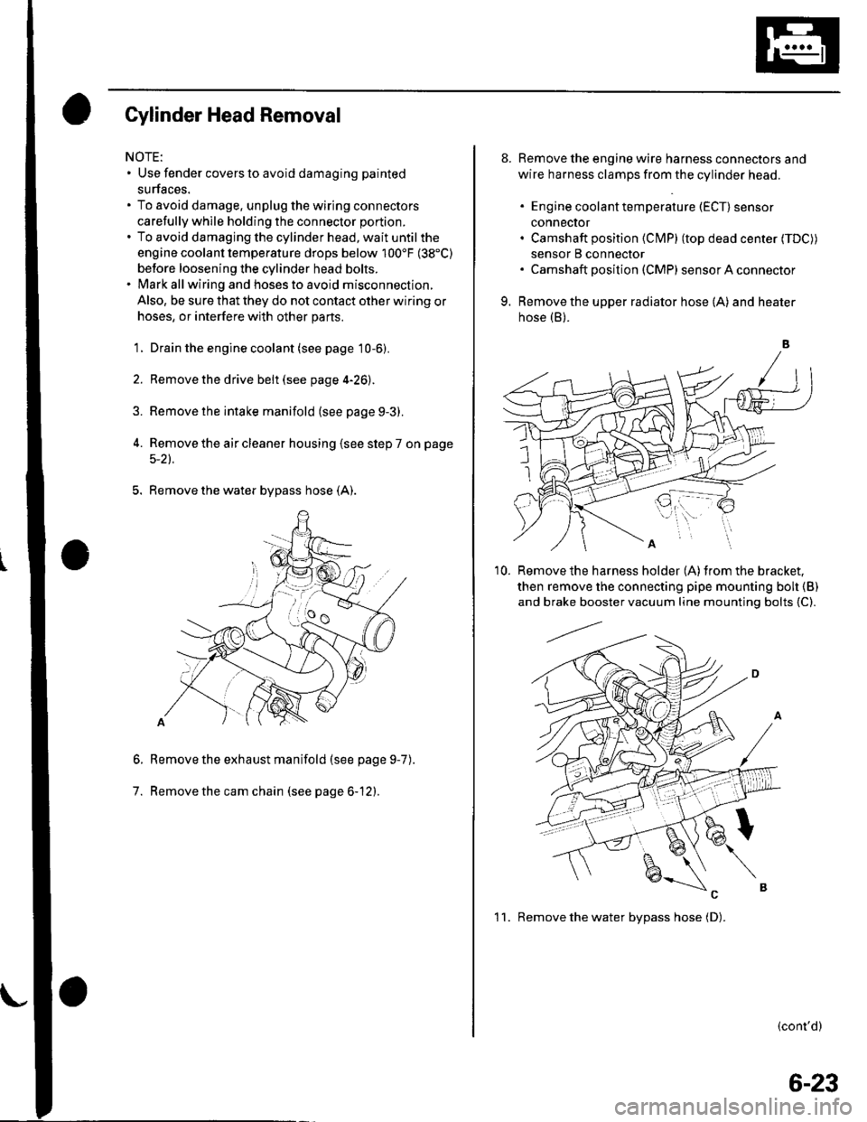
5. Remove the water bypass hose (A).
Remove the exhaust manifold (see page 9-7
Remove the cam chain (see page 6-12).
6.
7.
).
8. Remove the engine wire harness connectors and
wire harness clamps from the cylinder head.
. Engine coolant temperature (ECT) sensor
conneclor. Camshaft position (Cl\4P) (top dead center (TDC))
sensor B connector. Camshaft posilion (CMP) sensor A connector
9. Remove the upper radiator hose (A) and heater
hose (B).
'10. Remove the harness holder (A)from the bracket,
then remove the connecting pipe mounting boh {B)
and brake booster vacuum line mounting bolts {C).
(cont'd)
1 1. Remove the water bvpass hose (D).
6-23
Page 135 of 1139

Cylinder Head
8.
Cylinder Head lnstallation (cont'd)
7.Apply engine oil to the bolt threads and under thebolt heads of all the cylinder head bolts.
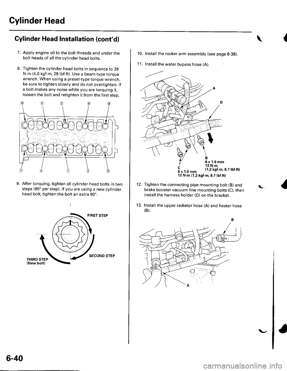
Tighten the cylinder head bolts in sequence to 39N.m {4.0 kgf.m, 29 lbf.ft). Use a beam-type torquewrench. When using a preset-type torque wrench,be sure to tighten slowly and do not overtighten. lf
a bolt makes any noise while you are torquing it,
loosen the bolt and retighten it from the first step.
9.After torquing, tighten all cylinder head bolts in twosteps (90" per step). lf you are using a new cylinderhead bolt, tighten the bolt an extra 90..
FIRST STEP
SECOND STEP
6-40
v
{\
10. Installthe rocker arm assembly {see page 6-38).
1't .Install the water bypass hose (A).
---l.-.
B6x1.0mm'r2 N.m(1.2 kgl.m,8.7 lbf.ftl
12.
't3.
c6xl.0mm'12 N,m (1.2 kgt.m,8.7 lbf.ft)
Tighten the connecting pipe mounting bolt (B) andbrake booster vacuum line mounting bolts (C), theninstallthe harness holder (D) on the bracket.
Installthe upper radiator hose {A) and heater hose(B).
Page 152 of 1139

Engine Block
Crankshaft lnspection
Out-ol-Round and Taper
1. Remove the crankshaft from the cylinder block (see
page 7-121.
2. Clean the crankshaft oil passages with pipe
cleaners or a suitable brush.
3. Clean the keyway and threads.
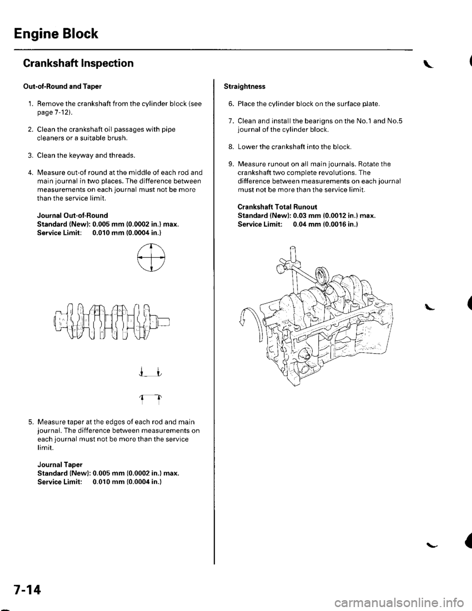
4. Measure out-of round at the middle of each rod and
main journal in two places. The difference between
measurements on each journal must not be more
than the service Iimit.
Journal Out-ot-Round
Standard (New): 0.005 mm (0.0002 in.) max.
Service Limit; 0.010 mm (0.0004 in.)
5. Measure taper at the edges of each rod and mainjournal. The difference between measurements on
each journal must not be more than the service
limit.
JournalTaper
Standard lNewl: 0.005 mm (0.0002 in.) max.
Service Limit: 0.010 mm {0.0004 in.)
I_JJ
fl
7-14
\
Straightness
6. Place the cylinder block on the surface plate.
7. Clean and installthe bearigns on the No.1 and No.5journal of the cylinder block.
8. Lower the crankshaft into the block.
9. Measure runout on all main journals. Rotate the
crankshaft two complete revolutlons. The
difference between measurements on each journal
must not be more than the service limit.
Crankshaft Total Runout
Standard (New): 0.03 mm 10.0012 in.l max.
Service Limit: 0.04 mm (0.0016 in.l
(L
{
Page 169 of 1139
Component Location Index
OIL PUMPCHAIN TENSIONER
DRAIN BOLT
OIL PANRemoval, page 7 11Installataon, page 7-27
OIL PUMPOverhaLrl, page 8-8
HL]
BAFFLE PLATE
OIL FILTER FEED PIPEReplacement, page 8-7
OIL FILTERReplacement, page 8-6
OIL CONTROLORIFICE
WASHER
OIL PRESSURE SWITCHSwitch Test, page 8 4Oil Pressure test, page 8'4Replacement, page 8 16
-&\JrI
--t N\ksrarr lN-?cKEr dczt$)
#1
\OIL PUMPCHAIN GUIDE
8-3
Page 173 of 1139
Oil Filter Feed Pipe Replacement
1.Remove the oilfilter (see page 8-6).
Remove the oil filter feed pipe.
3. lnstallthetwo20 x 1.5mmnuts(A) ontothenew
oil filter feed pipe. Hold the nut with a wrench, then
tighten the other nut.
4. Tightenthe oil filterfeed pipetothe blockto 49 N.
m {5.0 kgf.m, 36 lbf ft), then remove the nuts from
the oil filter feed oiDe.
8-7
Page 183 of 1139
Engine Mechanical
Intake Manifold and Exhaust System
lntake Manifold Removal and Installation ................. 9-2
Exhaust Manifold Removal and Installation .............. 9-7
Exhaust Pipe and Muffler Replacement ..................... 9-8
r
r-!i!1