2003 HONDA CIVIC switch
[x] Cancel search: switchPage 1118 of 1139
42. Turn the ignition switch OFF.
43. lf necessary, remove the SCS service connector
from the l\4ES connector.
44. Turn the ignition switch ON {ll}.
Does the SBS indicator come on for about 6
seconds and then go off?
YES -The system is OK at this time. t
NO Go to step 45.
45. Disconnect SRS unit connector C (8P) fromtheSRS
unit (see step 7 on page 23-221.
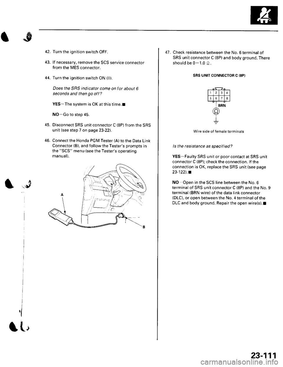
46. Connect the Honda PGM Tester {A) to the Data Link
Connector (B), and follow the Tester's prompts in
the "SCS" menu (see the Tester's operating
manu a l).
t .r9
I
,l
IL,
23-111
47. Check resistance between the No. 6 terminal of
SRS unit connector C (8P) and body ground. There
should be 0-1.0 Q.
SRS UNIT CONNECTOR C I8P)
Wire side of female terminals
ls the resistance as specified?
YES Faulty SRS unit or poor contact at SRS unit
connector C (8P); check the connection. lf the
connection is OK, replace the SRS unit (see page
23-1221..
NO Open in the SCS line between the No.6
terminal of SRS unit connector C (8P) and the No. 9
terminal (BRN wire) ofthe data link connector(DLC), or open between the No. 4 terminal of the
DLC and body ground. Repair the open wire(s).1
I2
50
BRN
n
Page 1119 of 1139
sRs
Component Replacement/lnspection After Deployment
NOTE: Before doing any SRS repairs. use the PGM
Tester SRS menu method to check for DTCS; refer to the
DTC Troubleshooting Index for the less obvious
deployed parts (seat beit tensioners, front sensors, side
airbag sensors, etc.)
After a collision where the seat belt tensioners
deployed, replace these items:' Seat belt tensioners. Seat belt buckle tensioners. SRS unit. Front impact sensors
After a collision where the front airbag(s) deployed.
replace these items:. SRS unit. Deployed airbag(s). Seat belt tensioners. Seat belt buckle tensioners. Front impact sensors
After a collision where the side airbag{s) deployed,
replace these items:. SRS unit. Deployed side airbag(s). Side impact senso(s)for the side(s) that deployed
During the repair process, inspect these areas:
. lnspect allthe SRS wire harnesses. Replace, don't
repair, any damaged harnesses.. Inspectthecable reelfor heatdamage. lf there is any
damage, replace the cable reel.
Afterthe vehicle is completely repaired, turn the
ignition switch ON (ll). lf the SRS indicator comes on for
about 6 seconds and then goes off, the SRS airbag
system is OK. lf the indicator does not function properly,
use the PGM Tester SRS Menu Method to read the DTC
(see page 23-23). lf this doesn't retrieve any codes, use
the Tester's SCS menu method (see page 23-24). lf you
still cannot retrieve a code, go to SRS Indicator Circuit
Troubleshooting.
23-112
\|J
Page 1120 of 1139
A
\'l9
Driver's Airbag Replacement
Removal
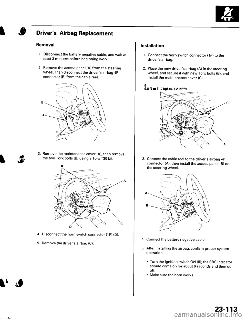
1. Disconnectthe battery negative cable, and wait atleast 3 minutes before beginning work.
2. Remove the access panel (A) from the steering
wheel, then disconnect the driver's airbag 4p
connector (B)from the cable reel.
Remove the maintenance cover (A), then remove
the two Torx bolts (B) using a Torx T3O bit.
Disconnect the horn switch connector (1P) (D).
Remove the driver's airbag (C).5.
lfc
23-113
Installation
1. Connect lhe horn switch connector (1P) to thedriver's airbag.
2. Place the new driver's airbag (A) inthesteering
wheel, and secure it with new Torx bohs (B), and
installthe maintenance cover (C).
a9.8 N.m {1.0 kgf.m, 7.2 lbt.ft)
Connect the cable reel to the driver's airbag 4P
connector (A), then installthe access panel (B) on
the steering wheel.
Connect the battery negative cable.
After installing the airbag, confirm proper system
operation:
. Turn the ignition switch ON (ll); the SRS indicator
should come on for about 6 seconds and then go
off.. Make sure the horn works.
4.
5.
Page 1121 of 1139
sRs
Front Passenger's Airbag Replacement
Removal
1. Disconnectthe battery negative cable, and wait at
least 3 minutes before beginning work,
2. Remove the glove box stops, and lower the glove
box.
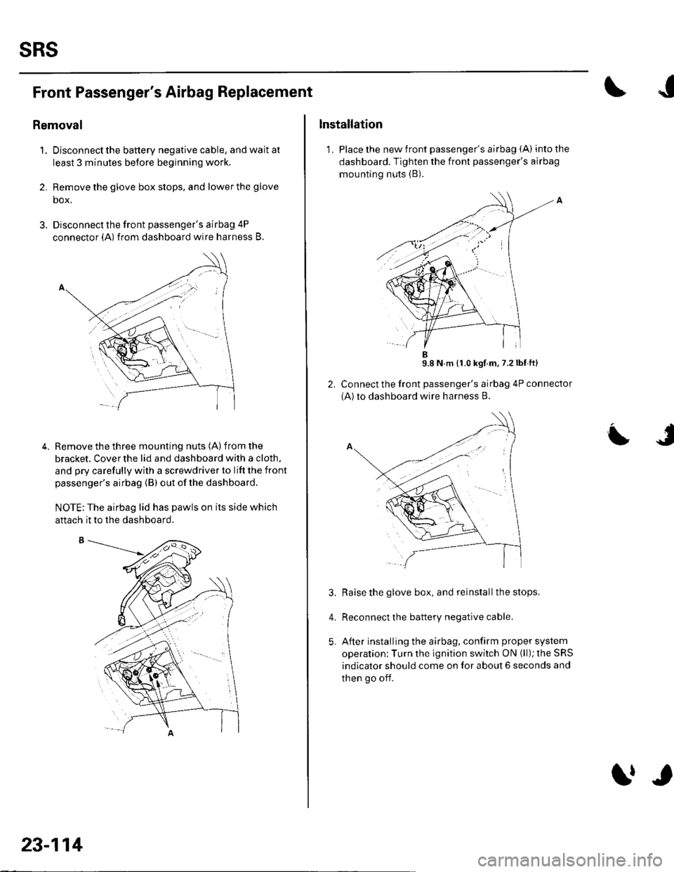
3. Disconnect the front passenger's airbag 4P
connector (A) from dashboard wire harness B.
Remove the three mounting nuts (A) from the
bracket. Cover the lid and dashboard with a cloth,
and pry carefully with a screwdriver to lift the front
passenger's airbag (B) out ofthe dashboard.
NOTE:The airbag lid has pawls on its side which
4.
aftach it to the dashboard.
23-114
trr
Installation
1. Place the new front passenger's airbag (A) into the
dashboard. Tighten the front passenger's airbag
mounting nuts (B).
9.8 N m {1.0 kgf.m,7.2lbf ft}
Connect the front passenger's airbag 4P connector
(A)to dashboard wire harness B.
Raise the glove box, and reinstall the stops.
Reconnect the battery negative cable.
After installing the airbag, confirm proper system
operation; Turn the ignition switch ON (ll); the SRS
indicator should come on for about 6 seconds and
then go off.
L
4.
Page 1122 of 1139
)Side Airbag Replacement
)
NOTE: Review the seat replacement pro6edure in the
Body section before pertorming repairs or service.
Removal
1. Disconnectthe battery negative cable, and wait atleast 3 minutes before beginning work.
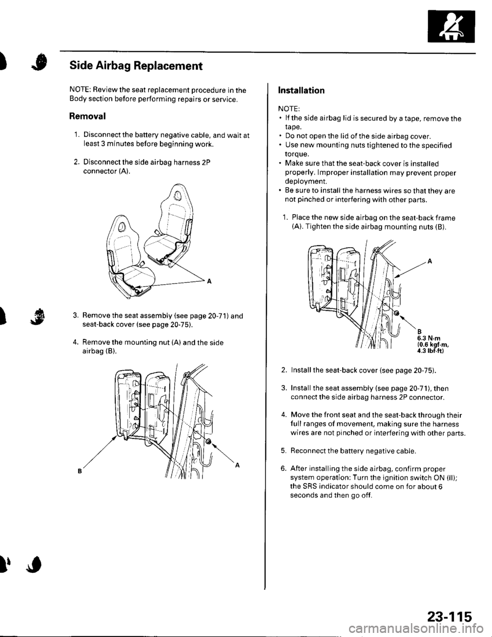
2. Disconnect the side airbag harness 2P
connector {A).
Remove the seat assembly (see page 20-71) and
seat-back cover (see page 20-75).
Remove the mounting nut (A) and the side
airbag (B).
3.
l,o
23-115
Installation
NOTE:. lf the side airbag lid issecured byatape, removelhe
rape.. Do not open the lid of the side airbag cover.. Use new mounting nuts tightened to the specified
torque.. Make sure that the seat-back cover is installedproperly, lmproper installation may prevent proper
deployment.. Be sure to install the harness wires so that they arenot pinched or interfering with other parts.
1. Place the new side airbag on the seat-back frame(A). Tighten the side airbag mounting nuts (B).
2. Installthe seat-back cover {see page 20-75).
3. Installthe seat assembly (see page 20-71), then
connect the side airbag harness 2P connector.
4. Move the front seat and the seat-back through their
full ranges of movement, making sure the harness
wires are not pinched or interfering with other parts.
5. Reconnect the battery negative cable.
6. After installing the side airbag, confirm proper
system operation;Turn the ignition switch ON (ll);
the SRS indicator should come on for about 6
seconds and then go off.
Page 1123 of 1139
sRs
Airbag Disposal
Special Tool Required
Deployment tool 07HAz-SG00500
Before scrapping any airbags, side airbags, seat belt
tensioners, or seat belt buckle tensioners (including
those in a whole vehicle to be scrapped), the airbags,
side airbags, seat belt tensioners, or seat belt buckle
tensioners must be deployed. lf the vehicle is still within
the warranty period, the Honda District Service
Manager must give approval and/or special instruction
before deploying the airbags, side airbags, seat belt
tensioners, or seat belt buckle tensioners. Only after the
airbags, side airbags, seat belt tensioners, or seat belt
buckle tensioners have been deployed (as the result of
vehicle collision, for example), can they be scrapped.
lf the airbags, side airbags, seat belt tensioners, and
seat belt buckle tensioners appear intact (not deployed),
treat them with extreme caution. Follow this Drocedure.
Deploying Airbags in the Vehicle
lf an SRS equipped vehicle is to be entirely scrapped, its
airbags, side airbags. seat belt tensioners. and seat belt
buckle tensioners should be deoloved while still in the
vehicle. The airbags, side airbags, seat belttensioners,
and seat belt buckle tensioners should not be
considered as salvageable parts and should never be
installed in another vehicle.
1. Turn the ignition switch OFF, then disconnect the
battery negative cable, and wait at least 3 minutes.
2. Confirm that each airbag, side airbag, or seat belt
tensioner is securely mounted.
3. Conf irm that the specia I tool isfunctioning properly
by following the check procedure on the tool label.
23-116
$J
Driver's Airbag:
4. Remove the access panel f rom the steering wheel,
then disconnect the driver's airbag 4P connector
from the cable reel (see step 2 on page 23-21).
Front Passenger's Airbag:
5. Lowerthe glove box, then disconnectthe front
passenger's airbag 4P connector from dashboard
wire harness B (see step 3 on page 23-211.
Side Airbag:
6. Disconnect the side airbag 2P connectors from the
floor wire harness (see step 4 on page 23-211.
Seat belt tensioner:
7. Disconnect the seat belt tensioner 2P connectors
from the floor wire harness {see step 5 on page 23-
22). Pull the seat belt out all the way, and cut it off.
Seat belt buckle tensioner:
8, Disconnect the seat belt buckle tensioner 4P
connectors from the floor wire harness (see step 6
on page 23-221.
Page 1124 of 1139
)
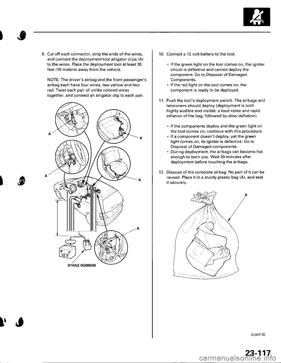
9. Cut off each connector, strip the ends of the wires,
and connect the deployment tool alligator clips (A)
to the wires. Place the deployment tool at least 30
feet (10 meters) away from the vehicle.
NOTE: The driver's airbag and the front passenger's
airbag each have four wires, two yellow and two
red. Twist each Dair of unlike colored wires
together, and connect an alligator clip to each pair.
I
!
10. Connect a 12 volt battery to the tool.
. lf the green light on the tool comes on, the igniter
circuit is defective and cannot deDlov the
component. Go to Disposal of Damaged
ComDonents.. lf the red light on the tool comes on, the
component is ready to be deployed.
11. Push the tool's deployment switch. The airbags and
tensioners should deploy (deployment is both
highly audible and visible: a loud noise and rapid
inflation of the bag, followed by slow deflation).
. lf the components deploy and the green light on
the tool comes on, continue with this procedure.
. lf a component doesn't deploy, yet the green
light comes on, its igniter is defective. Go to
Disposal of Damaged components.. During deployment, the airbags can become hot
enough to burn you. Wait 30 minutes after
deployment before touching the airbags.
12. Dispose ofthe complete airbag. No pan of it can be
reused. Place it in a sturdy plastic bag (A), and seal
rt securery.
(cont'd)
/:
i'..-':
23-117
Page 1125 of 1139
sRs
Airbag Disposal (cont'dl
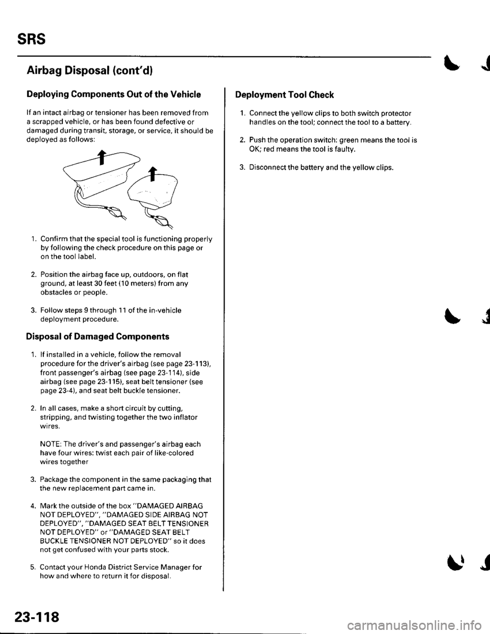
Deploying Components Out of the Vehicle
lf an intact airbag or tensioner has been removed from
a scrapped vehicle, or has been found defective or
damaged during transit, storage, or service, it should be
deoloved as follows:
1. Confirm that the special tool isfunctioning properly
by following the check procedure on this page or
on the tool label.
2. Position the airbag face up, outdoors, on flat
ground, at least 30 feet (10 meters) from any
obstacles or DeoDle.
3. Follow steps 9 through 1 1 of the in-vehicle
deployment procedure.
Disposal of Damaged Components
1. lf installed in a vehicle, follow the removal
procedure for the driver's airbag (see page 23-113),
front passenger's airbag (see page 23-114), side
airbag (see page 23-115). seat belt tensioner (see
page 23-4), and seat belt buckle tensioner.
2. In all cases. make a short circuit by cutting,
stripping, and twisting together the two inflator
wires.
NOTE; The driver's and passenger's airbag each
have four wires: twist each pair of like-colored
wires together
Package the component in the same packaging that
the new reolacement Dart came in.
Mark the outside of the box "DAMAGED AIRBAG
NOT DEPLOYED'" ''DAMAGED SIDE AIRBAG NOT
DEPLOYED", "DAMAGED SEAT BELT TENSIONER
NOT DEPLOYED" or "DAlvlAGED SEAT BELT
BUCKLE TENSIONER NOT DEPLOYED" so it does
not get confused with your parts stock.
Contact your Honda District Service Manager for
how and where to return it for disposal.
23-118
I|J
J
Deployment Tool Check
1. Connect the yellow clips to both switch protector
handles on the tool; connect the tool to a battery.
2. Push the operation switch: green means the tool is
OK; red means the tool is faulty
3. Disconnectthe battery and the yellow clips.
J