Page 1074 of 1139
t
6. Reconnect the battery negative cable.
7. Erase the DTC memory.
8. Read the DTC.
ls DTC 22-4 indicated?
YES Go to step g.
NO-Short to power in the front passenger,s seatbelt buckle tensioner; replace the front passenger,s
seat belt buckle. !
9. Turn the ignition switch OFF. Disconnect the
battery negative cable, and wait for 3 minutes,
10.Disconnect both side airbag 2P connectors (see
step 4 on page 23-21)and the driver's seat beltbuckle tensioner 4P connector (see step 6 on page,1_r'>\
Disconnect SRS unit connector B (18P) from theSRS unit (see step 7 on page 23-221.
Disconnect the special tool from the floor wireharness.
Reconnect the battery negative cable.
Turn the ignition switch ON (ll).
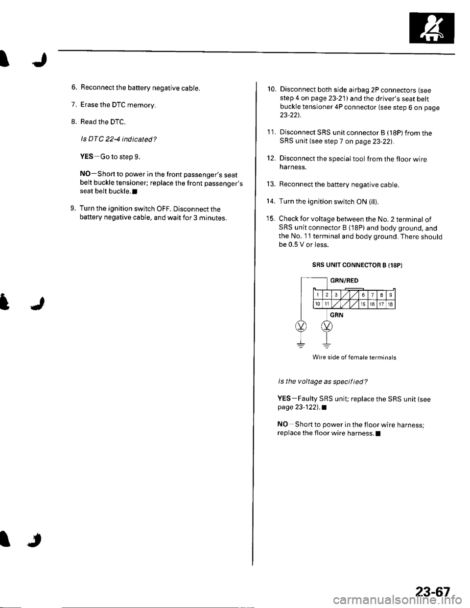
Check for voltage between the No. 2 terminal ofSRS unit connector B {18P) and body ground, andthe No. 11 terminal and body ground. There shouldbe 0.5 V or Iess.
SRS UNIT CONNECTOR B I18P)
ls the voltage as specified?
YES-Faulty SRS unit; replace the SRS unit (see
page 23-1221 .l
NO Short to power in the floor wire harness;
replace the floor wire harness.l
11.
't2.
t5.
14.
23-67
Page 1075 of 1139
sRs
DTC Troubleshooting (cont'dl
DTC 22-5: Short to Ground in Front
Passenger's Seat Belt Buckle Tensioner
Special Tools Required. SRS inflator simulator 07SAZ-T84011A. SRS simulator lead F 07XAZ-S230100
1 . Erase the DTC memory (see page 23-26).
2. Turn the ignition switch ON (ll), and check that the
SRS indicator comes on for about 6 seconds and
then goes off.
Does the SRS indicator stay on?
YES-Go to step 3.
NO - Intermittent failure, system is OK at this time.
Go to Troubleshooting Intermittent Failures (see
page 23-26).
3. Turn the ignition switch OFF. Disconnectthe
battery negative cable, and wait for 3 minutes.
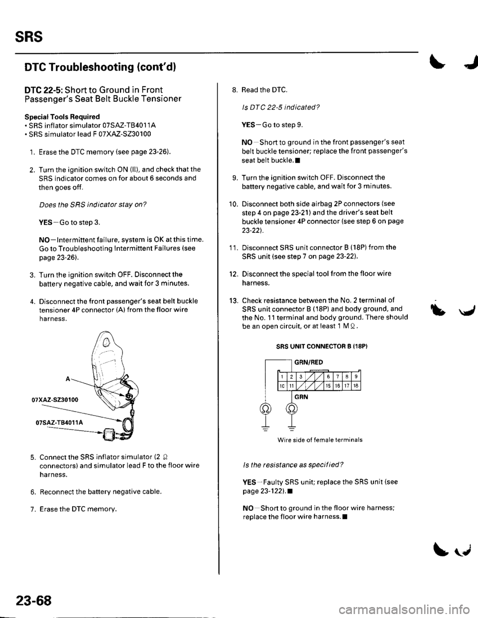
4. Disconnectthe front passenger's seat belt buckle
tensioner 4P connector (A) from the floor wire
harness,
Connect the SRS inflator simulator (2 Q
connectors) and simulator lead F to the floor wire
narness.
Reconnect the battery negative cable.
Erase the DTC memory.
5.
6.
1.
23-68
!U
8. Read the DTC.
ls DTC 22-5 indicated?
YES-Go to step 9.
NO Short to ground in the front passenger's seat
belt buckle tensioner; replace the front passenger's
seat belt buckle.l
9. Turn the ignition switch OFF. Disconnectthe
battery negative cable, and wait for 3 minutes.
10. Disconnect both side airbag 2P connectors (see
step 4 on page 23-21) and the driver's seat belt
buckle tensioner 4P connector (see step 6 on page
23-22t.
11. Disconnect SRS unit connector B (18Plfrom the
SRS unit (see step 7 on page 23-221.
12. Disconnect the special tool from the floor wire
harness,
13. Check resistance between the No. 2 terminal of
SRS unit connector B (18P) and body ground, and
the No, 11 terminal and body ground. There should
be an open circuit, or at least 1 M Q.
SRS UNIT CONNECTOR g {18PI
ls the resistance as specified?
YES-Faulty SRS unit; replace the SRS unit (see
page 23-1221 .a
NO Short to ground in the floor wire harness;
replace the floor wire harness.l
bU
Wire side of female terminals
Page 1076 of 1139
I
DTC s-1, 5-2, 5-4, s-8, 6-3, 6-4,6-7,6-8,7-1,
7-2,7-3, A-1,4-2, 8-3, 8-4, 8-5, 8-6, 9-1, 9-2:
Internal Failure of the SRS Unit
NOTE: Before troubleshooting any of these DTCs, check
the battery/system voltage. lf the voltage is low, repair
the charging system or replace the battery before
troubleshooting the SRS. lf the battery/system voltage
is now OK, ask the customer if the battery ever went
oeao,
1. Erase the DTC memory (see page 23-26).
2. Turn the ignition switch ON (ll), and check that the
SRS indicator comes on for about 6 seconds and
then goes off.
Does the SRS indicatot stay on?
YES Replace the SRS unit (see page 23-122).1
NO Intermittent failure, system is OK at this time.
Go to Troubleshooting lntermittent Failures (see
page 23-26).
l
I
DTC 10-1, 10-2, 10-3, 10-4, 10-s, 10-6, 10-7:
Airbags, Side Airbags, and/or Seat Belt and
Seat Belt Buckle Tensioners Deployed
The SRS unit must be replaced after any airbags and/or
tensioners have deployed (see page 23-122). !
23-69
Page 1077 of 1139
SRS
DTC Troubleshooting (cont'd)
DTC 13-1, 13-2: Internal Failure of the Driver's
Side lmpact Sensor
1. Erase the DTC memory (see p age 23-26).
2. Turn the ignition switch ON (ll), and check that the
SRS indicator comes on for about 6 seconds and
then goes off.
Does the SRS indicatot stay on?
YES Replace the driver's side impact sensor (see
page 23-123) .a
NO Intermittent failure, system is OK at this time.
Go to Troubleshooting Intermittent Failures (see
page 23-261.
23-70
IJ
DTC 14-1, 14-2: Internal Failure ofthe Front
Passenger's Side lmpact Sensor
1. Erase the DTC memory (see page 23-26).
2. Turn the ignition switch ON (ll), and check that the
SRS indicator comes on for about 6 seconds and
then goes off.
Does the SRS indicator stay on?
YES-Replace the front passenger's side impact
sensor (see page 23-123],.1
NO-lntermittent failure, system is OK at this time.
Go to Troubleshooting Intermittent Failures (see
page 23-26).
U
Page 1078 of 1139
I
DTC 9-3: Fau lty Driver's Seat Belt Buckle
Switch
1. Erase the DTC memory (see page 23 26).
2. Turn the ignition switch ON (ll), then buckle and
unbuckle the driver's seat belt several times.
3. Read the DTC.
ls DTC 9-3 indicated?
YES Go to step 4.
NO Intermittent failure, system is OK at this time.
Go to Troubleshooting Intermittent Failures (see
page 23-261.
Turn the ignition switch OFF.
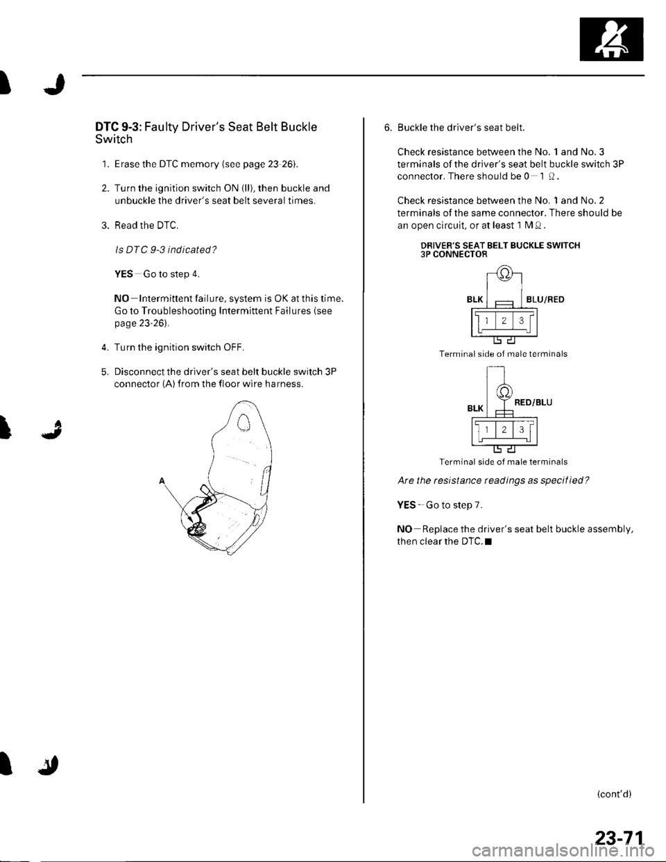
Disconnect the driver's seat belt buckle switch 3P
connector (A) from the floor wire harness.
4.
5.
t
I
6. Buckle the driver's seat belt.
Check resistance between the No. 1 and No.3
terminals ofthe driver's seat belt buckle switch 3P
conneclor. There should be 0 1 (J.
Check resistance between the No. 1 and No.2
terminals of the same connector. There should be
an open circuit, or at least 1 M Q .
DRIVER'S SEAT BELT BUCKLE SWITCH3P CONNECTOR
BLU/RED
Terminal side of male terminals
Terminal side of male terminals
Ate the resistance readings as specif ied?
YES - Go to step 7.
NO Replace the driver's seat belt buckle assembly,
then clear the DTC.I
(cont'd)
23-71
Page 1079 of 1139
sRs
DTC Troubleshooting (cont'dl
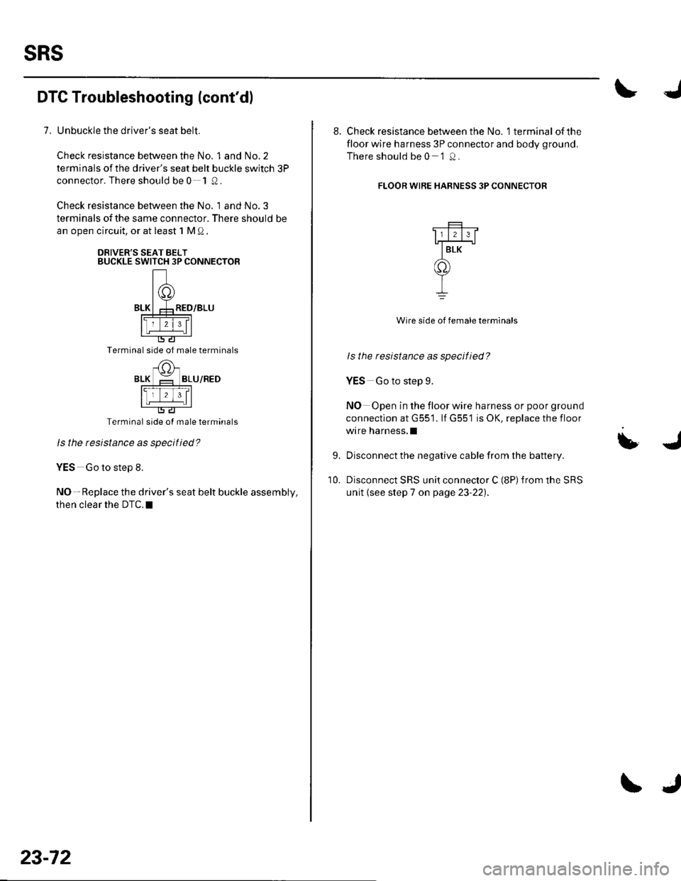
7, Unbuckle the driver's seat belt.
Check resistance between the No. 1 and No.2
terminals ofthe driver's seat belt buckle switch 3P
connector. There should be 0 1 Q.
Check resistance between the No. 1 and No. 3
terminals of the same connector. There should be
an open circuit, or at least 1 M Q
DRIVER'S SEAT BELTBUCKLE SWITCH 3P CONNECTOR
Terminal side of male terminals
BLU/RED
Terminal side oI male terminals
ls the rcsistance as specified?
YES Go to step 8.
NO-Replace the driver's seat belt buckle assembly,
then clear the DTC.I
23-72
\J
8. Check resistance between the No. 1 terminal ofthe
floor wire harness 3P connector and bodv oround.
There should be 0 '1 0.
FLOOR WIRE HARNESS 3P CONNECTOR
Wire side of female terminals
ls the resistance as specified?
YES Go to step 9.
NO Open in the floor wire harness or poor ground
connection at G551. lf G55'1 is OK, replace the floor
wrre harness.l
Disconnect the negative cable from the battery.
Disconnect SRS unit connector C (8P) from the SRS
unit {see step 7 on page 23-22).
9.
10.
Page 1081 of 1139
SRS
DTC Troubleshooting (cont'dl
DTC 9-4: Faulty Front Passenger's Seat Belt
Buckle Switch
1. Erase the DTC memory {see page 23-26).
2. Turn the ignition switch ON {ll), then buckle and
unbuckle the front passenger's seat belt several
times.
3. Read the DTC.
ls DTC 9-4 indicated?
YES-Go to step 4.
NO Intermittent failure, system is OK at this time.
Go to Troubleshooting Intermiftent Failures {seepage 23-26)'.
4. Turn the ignition switch OFF.
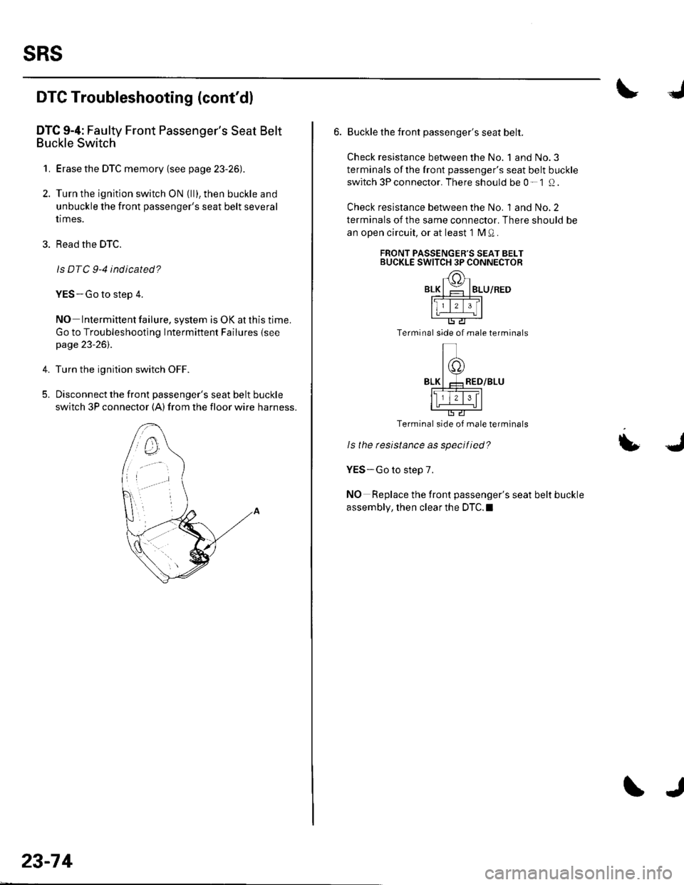
5. Disconnect the front passenger's seat belt buckle
switch 3P connector (A) from the floor wire harness.
23-74
J
6. Buckle the front passenger's seat belt.
Check resistance between the No. 1 and No.3
terminals of the front passenger's seat belt buckle
switch 3P connector. There should be 0- 1 Q.
Check resistance between the No. 1 and No.2
terminals of the same connector. There should be
an ooen circuit, or at least 1 M Q .
FRONT PASSENGER'S SEAT BELTBUCKLE SWITCH 3P CONNECTOR
BLU/RED
Terminal side of male terminals
Terminal side of male terminals
Is the rcsistance as specified?
YES-Go to step 7.
NO Replace the front passenger's seat belt buckle
assembly, then clear the DTC.I
Page 1082 of 1139
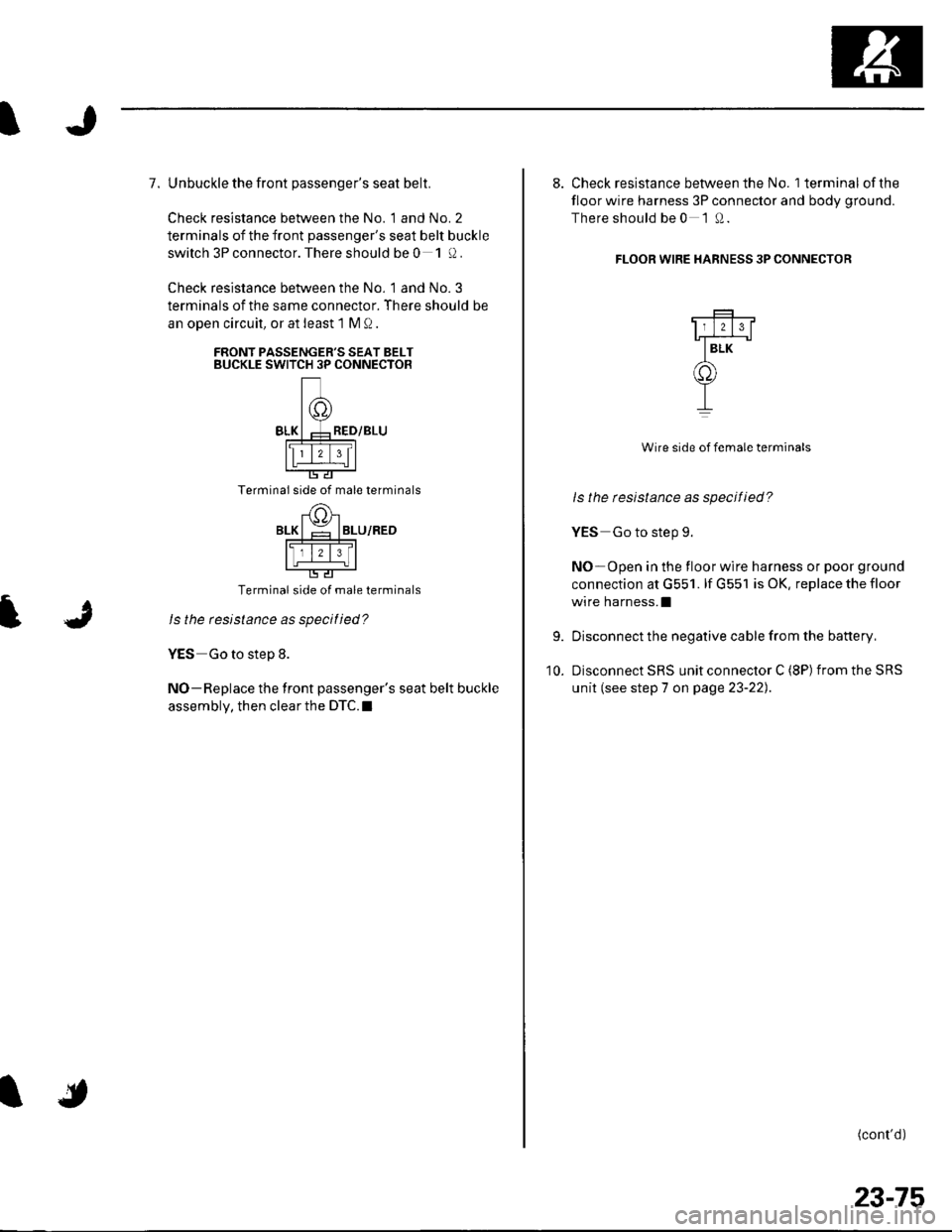
7. Unbuckle the front passenger's seat belt.
Check resistance between the No. 1 and No. 2
terminals of the front passenger's seat belt buckle
switch 3P connector. There should be 0 1!).
Check resistance between the No. 1 and No. 3
terminals of the same connector. There should be
an oDen circuit, or at least 1 M Q
FRONT PASSENGER'S SEAT BELTBUCKLE SWITCH 3P CONNECTOR
Terminal side of male terminals
Terminal side of male terminals
ls the resistance as specilied?
YES Go to step 8.
NO-Replace the front passenger's seat belt buckle
assembly, then clear the DTC.I
9.
10.
8. Check resistance between the No. 1 terminal ofthe
floor wire harness 3P connector and body ground.
There should be 0 1Q.
FLOOR WIRE HARNESS 3P CONNECTOR
Wire side of female terminals
ls the tesistance as specified?
YES Go to step 9.
NO-Open in the floor wire harness or poor ground
connection at G551. lf G551 is OK, replace the floor
wire harness.I
Disconnect the negative cable from the battery,
Disconnect SRS unit connector C (8P) from the SRS
unit (see step 7 on page 23-22).
(cont'd)
23-75