Page 147 of 1139

8.
9.
lf the plastigage measures too wide or too narrow,
remove the upper half of the bearing, install a new,
complete bearing with the same color code(s), and
recheck the clearance. Do not file. shim, or scrape
the bearings or the caps to adjust clearance.
lf the plastigage shows the clearance is still
incorrect, try the next larger or smaller bearing (the
color listed above or below that one), and check
clearance agaln. lf the proper clearance cannot be
obtained by using the appropriate larger or smaller
bearing, replace the crankshaft and stan over.
Rod Bearing Selection
1. Inspect each connecting rod for cracks and heat
damage.
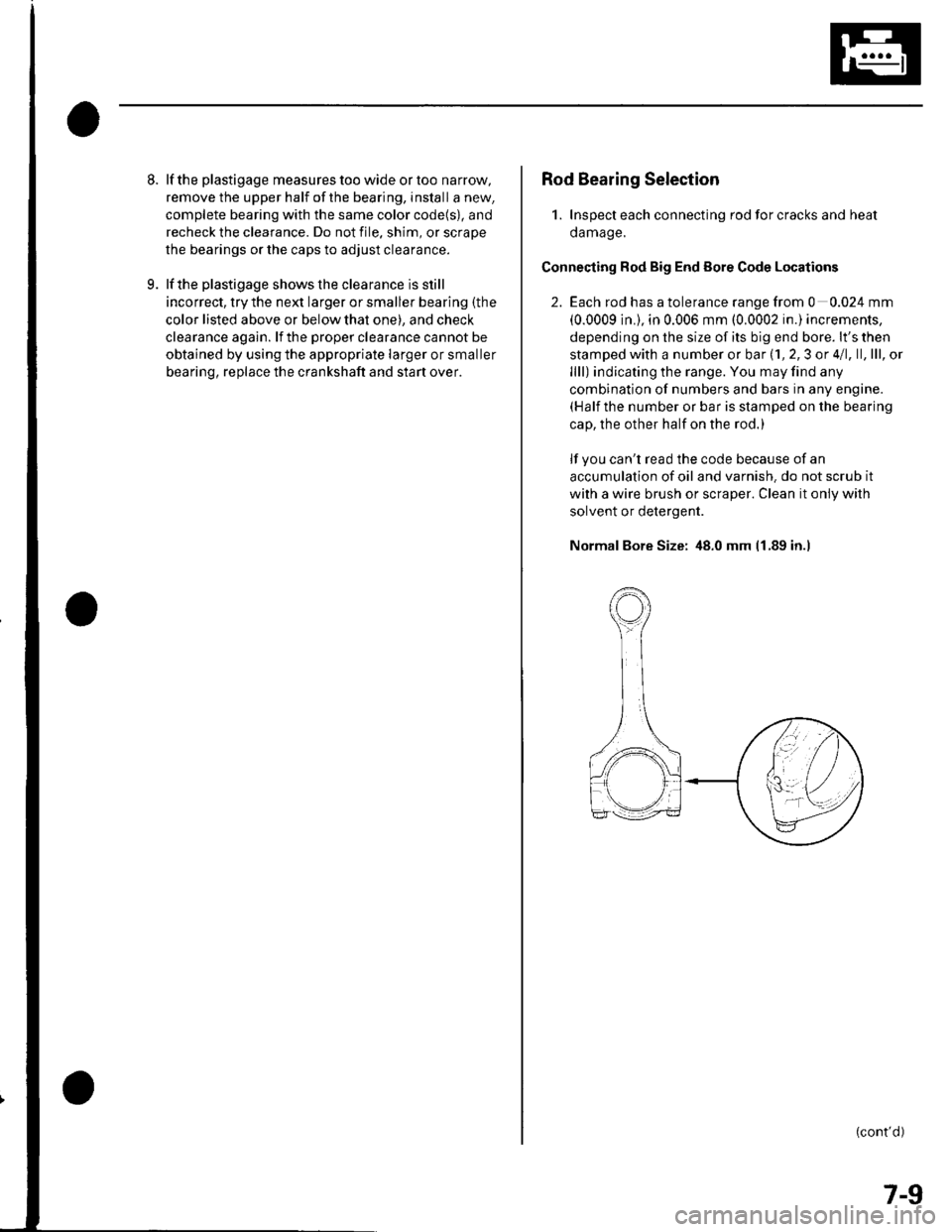
Connecting Rod Big End Eore Code Locations
2. Each rod has a tolerance range from 0 0.024 mm
(0.0009 in.), in 0.006 mm (0.0002 in.) increments,
depending on the size of its big end bore. lt's then
stamped with a number or bar (1, 2,3 or 4/1, ll,lll, ol
llll) indicating the range. You may find any
combination of numbers and bars in any engine.(Half the number or bar is stamped on the bearing
cap, the other half on the rod.)
lf you can't read the code because of an
accumulation of oil and varnish. do not scrub it
with a wire brush or scraper. Clean it only with
solvent or detergent.
Normal Bore Size: 48.0 mm 11.89 in.l
(cont'd)
7-9
Page 149 of 1139
1.
OilPan Removal
Drain the engine oil (see page 8-5).
lf the engine is still in the vehicle, remove the
subframe.
-1 Attach the chain hoist to the engine (see step
35 on page 5-6).-2 Disconnectthe suspension lower arm balljoints (see step 3 on page 18-19).-3 Remove the rear mounl mounting bolts (see
step 39 on page 5-7).-4 Remove the front mount mounting bolt (see
step 40 on page 5-7).-5 Use a marker to make alignment marks on the
reference lines that align with the centers of
the rear subframe mounting bolts. Remove the
front subframe (see step 43 on page 5-8).
Remove the bolts/nuts securing the oil pan.
Drive an oil pan seal cutter between the oil pan and
cylinder block.
5. Cut the oil panseal bystrikingthesideofthecutter
to slide the cutter along the oil pan.
6. Remove the oil pan.
7-11
Page 150 of 1139
Engine Block
Crankshaft and Piston Removal
1. Remove the engine assembly (see page 5-2).
2. Remove the transmission (see page 13-4).
3. Remove the oil pan (see page 7-1 1).
4. Remove the oil pump {see page 8-9).
5. Remove the cylinder head (see page 6-23).
6. Remove the baffle plates.
7. Remove the 8 mm bolts.
E
7-12
8. Remove the bearing cap bolts. To prevent warpage,
unscrew the bolts in sequence 1/3 turn at a time:
repeat the sequence until all bolts are loosened.
Remove the lower block and bearings, Keep all
bearings in order.
\L
(
Page 152 of 1139

Engine Block
Crankshaft lnspection
Out-ol-Round and Taper
1. Remove the crankshaft from the cylinder block (see
page 7-121.
2. Clean the crankshaft oil passages with pipe
cleaners or a suitable brush.
3. Clean the keyway and threads.
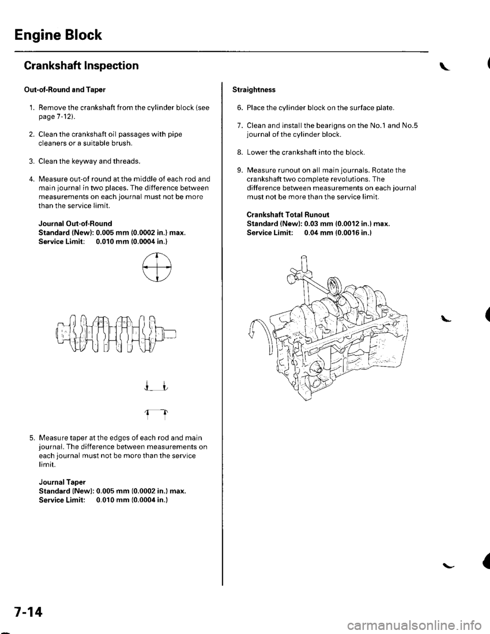
4. Measure out-of round at the middle of each rod and
main journal in two places. The difference between
measurements on each journal must not be more
than the service Iimit.
Journal Out-ot-Round
Standard (New): 0.005 mm (0.0002 in.) max.
Service Limit; 0.010 mm (0.0004 in.)
5. Measure taper at the edges of each rod and mainjournal. The difference between measurements on
each journal must not be more than the service
limit.
JournalTaper
Standard lNewl: 0.005 mm (0.0002 in.) max.
Service Limit: 0.010 mm {0.0004 in.)
I_JJ
fl
7-14
\
Straightness
6. Place the cylinder block on the surface plate.
7. Clean and installthe bearigns on the No.1 and No.5journal of the cylinder block.
8. Lower the crankshaft into the block.
9. Measure runout on all main journals. Rotate the
crankshaft two complete revolutlons. The
difference between measurements on each journal
must not be more than the service limit.
Crankshaft Total Runout
Standard (New): 0.03 mm 10.0012 in.l max.
Service Limit: 0.04 mm (0.0016 in.l
(L
{
Page 155 of 1139
Cylinder Honing
Only a scored or scratched cylinder bore should be
noneo.
Measure the cylinder bores {see page 7-15).
lf the block is to be reused, hone the cylinders and
remeasure the bores.
Hone the cylinder bores with honing oil and a fine(400 grit) stone in a 60 degree cross-hatch pattern
(A). Use only a rigid hone with 400 grit or finer
stone such as Sunnen, Ammco, or equivalent. Do
not use stones that are worn or broken.
When honing is complete, thoroughly clean the
engine block of all metal particles. Wash the
cylinder bores with hot soapy water, then dry and
oil them immediately to prevent rusting. Never use
solvent, it will only redistribute the grit on the
cylinder walls.
lf scoring or scratches are still present in the
cylinder bores after honing to the service limit,
rebore the cylinder block. Some light vertical
scoring and scratching is acceptable if it is not deep
enough to catch your fingernail and does not run
the full length of the bore.
'L
3.
7-17
Page 156 of 1139
Engine Block
Piston, Pin, and Connecting Rod Replacement
Disassembly
1. Remove the piston from the cylinder block (see
page 7 -12).
2. Apply engine oilto the piston pin snap rings (A),
and turn them in the ring grooves until the end
gaps are lined up with the cutouts in the piston pin
bores (B).
NOTE; Take care not to damage the ring grooves.
Remove both snap rings (A). Start at the cutout in
the piston pin bore. Remove the snap rings
carefully so they do not go flying or get lost. Wear
eve protection.
7-18
\"
4.Heat the piston and connecting rod assembly to
about 158'F (70"C), then remove the piston pin.
(\
Page 158 of 1139
Engine Block
Piston, Pin, and Connecting Rod Replacement (cont'd)
Reassembly
1. Install a piston pin snap ring (A).
Coat the piston pin bore in the piston, the bore in
the connecting rod, and the piston pin with engine
oil.
Heat the piston to about 158"F (70'C).3.
7 -20
\
4. Install the piston pin (A). Assemble the piston (B)
and connecting rod (C) with the arrow (D) and the
embossed mark (E) on the same side. -
Install the remaining snap ring (F).
Turn the snap rings in the ring grooves untilthe
end gaps are positioned at the bottom of the piston.
(
5.
6.
I
Page 159 of 1139

Piston Ring Replacement
1. Remove the piston {rom the cylinder block (see
page 7 -121.
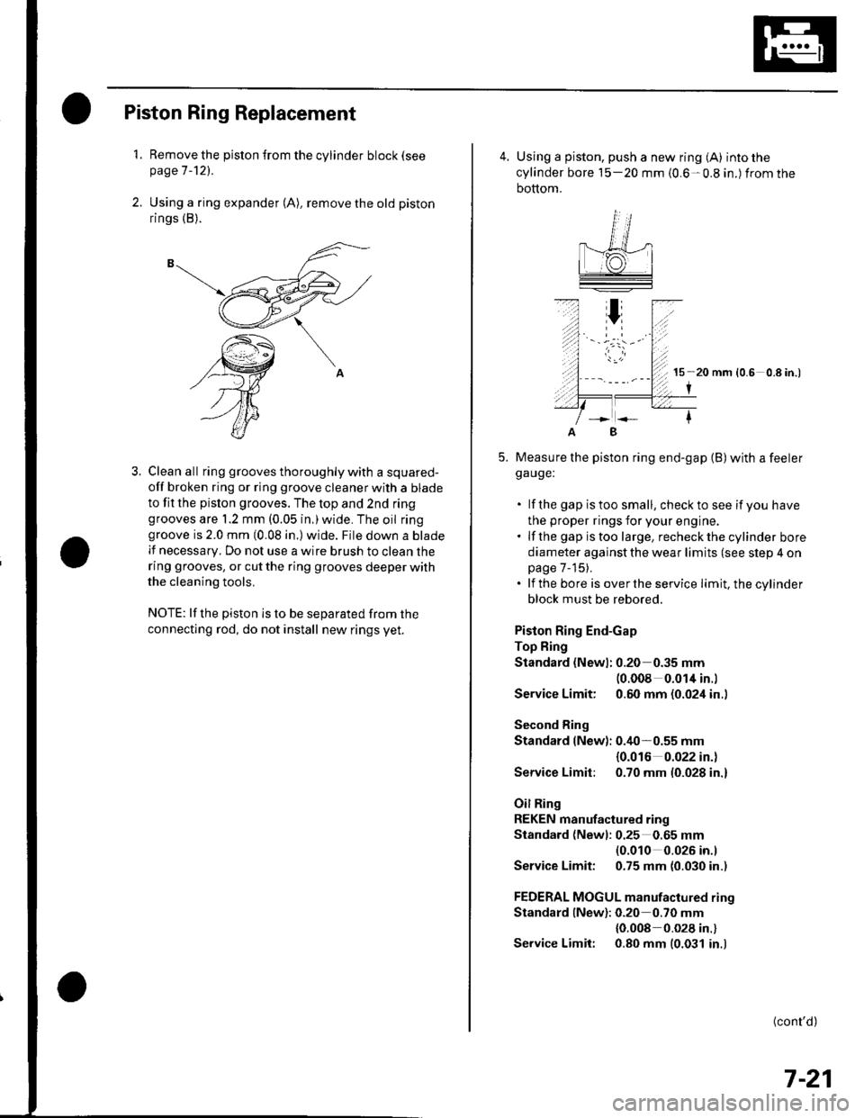
2. Using a ring expander (A), remove the old piston
rings (B).
3. Clean all ring grooves thoroughly with a squared-
off broken ring or ring groove cleaner with a blade
to fit the pislon grooves. The top and 2nd ringgrooves are 1.2 mm (0.05 in,)wide. The oil ringgroove is 2.0 mm (0.08 in.) wide. File down a blade
lf necessary. Do not use a wire brush to clean the
ring grooves, or cut the ring grooves deeper with
the cleaning tools.
NOTE: lf the piston is to be separated from the
connecting rod, do not install new rings yet.
4. Using a piston, push a new ring (A) into the
cylinder bore 15-20 mm {0.6-0.8 in.) from the
bottom.
15 20 mm (0.6 0.8 in.)
I
Measure the piston ring end-gap (B) with a feelerga uge:
. lf the gap istoo small, checkto see if you have
the proper rings for your engine.. lf the gap istoo large, recheckthecylinder bore
diameter against the wear limits (see slep 4 onpage 7-15).. lf the bore is overthe service limit, the cylinder
block must be rebored.
Piston Ring End-Gap
Top Fing
Standard (Newl: 0.20 0.35 mm(0.008 0.014 in.l
Service Limit: 0.60 mm (0.024 in..
Second Ring
Standard (New): 0.40-0.55 mm
{0.016 0.022 in.)
Service Limit: 0.70 mm (0.028 in.)
Oil Ring
REKEN manufactured ring
Standard (Newl: 0.25 0.65 mm(0.010 0.026 in.l
Service Limit: 0.75 mm (0.030 in.)
FEDERAL MOGUL manufactured rino
Standard lNew): 0.20 0.70 mm
{0.008 0.028 in.}
Service Limit: 0.80 mm (0.031 in.)
B
(cont'd)
7-21