Page 290 of 1139

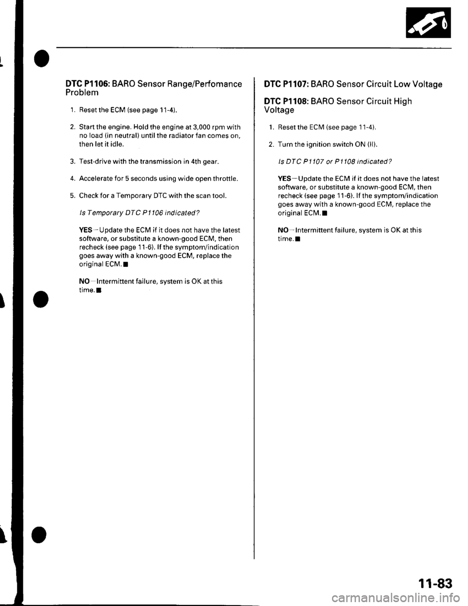
DTG Pl106: BARO Sensor Range/Perfomance
Problem
1. Reset the ECM (see page 11-4).
2. Start the engine. Hold the engine at 3,000 rpm with
no load (in neutral) until the radiator fan comes on,
then let it idle.
Test-drive with the transmission in 4th gear.
Accelerate for 5 seconds using wide open throttle.
Check for a Temporary DTC with the scan tool.
Is Temporary DTC Pl106 indicated?
YES-Update the ECM if it does not have the latest
software, or substitute a known-good ECM. then
recheck (see page 11-6). lf the symptom/indication
goes away with a known-good ECM, replace the
original ECM. !
NO Intermittent failure, system is OK at this
time.I
DTC Pl107: BARO Sensor Circuit Low Voltage
DTC Pl108: BARO Sensor Circuit High
Voltage
1. Reset the ECM {see page 1 1-4).
2. Turn the ignition switch ON (ll).
ls DTC P1107 or P1108 indicated?
YES-Update the ECM if it does not have the iatest
software, or substitute a known-good ECI\4, then
recheck (see page 11-6). lf the symptom/indication
goes away with a known-good ECM, replace the
original ECI\4.I
NO- Intermittent failure, system is OK at this
trme.l
11-83
Page 295 of 1139

PGM-FI System
DTC Troubleshooting (cont'dl
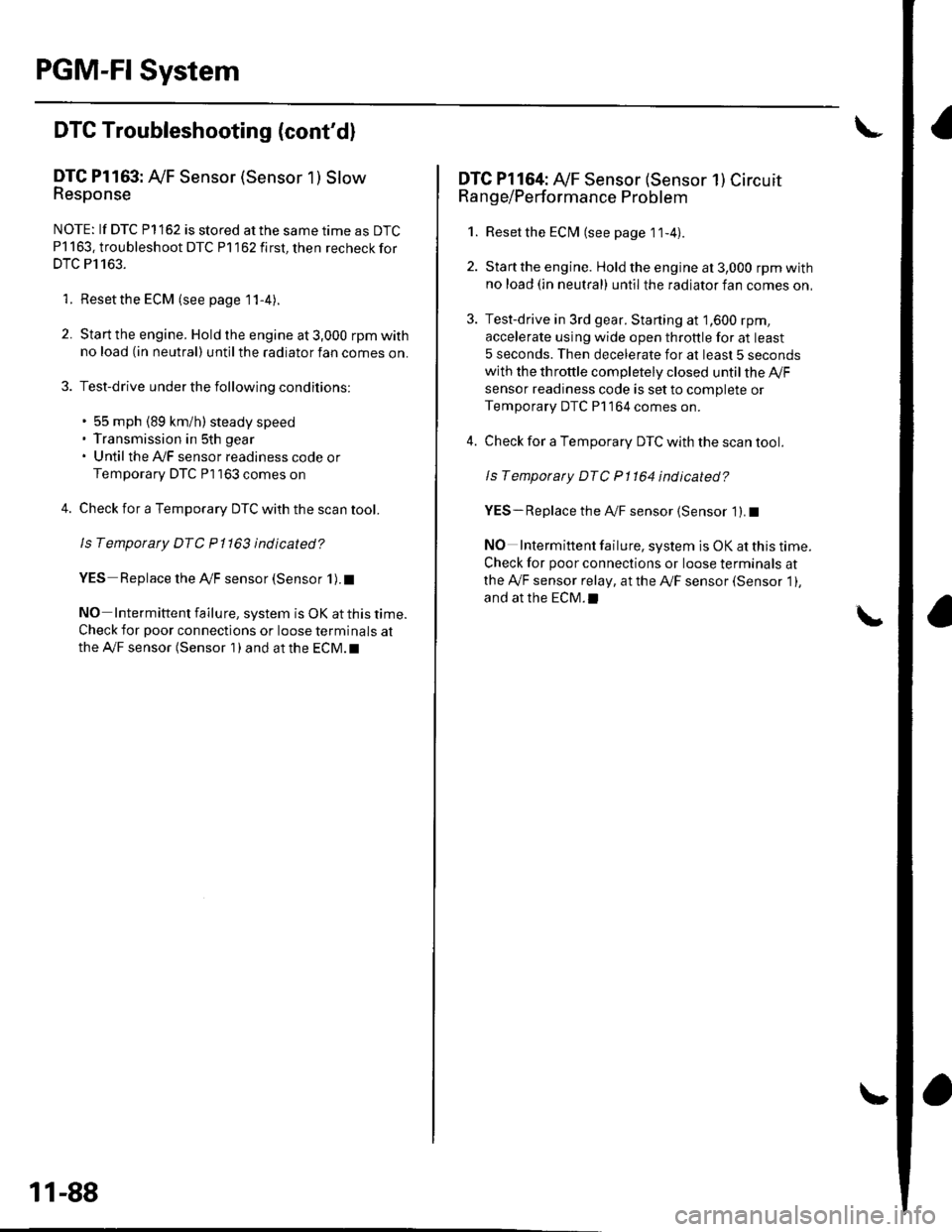
DTC Pl163: Ay'F Sensor (Sensor 1 ) SlowResponse
NOTE: lf DTC P1162 is stored at the same time as DTC
P1163. troubleshoot DTC P1162 first, then recheckfor
DTC P1163.
1. Reset the ECM (see page 1 1-4).
2. Start the engine. Hold the engine at 3,000 rpm with
no load (in neutral) until the radiator fan comes on.
3. Test-drive under the following conditions:
. 55 mph (89 km/h) steady speed' Transmission in sth gear' Until the Ay'F sensor readiness code or
Temporary DTC Pl163 comes on
4. Check for a Temporary DTC with the scan tool.
ls Temporary DTC P 1163 indicated?
YES Replace the Ay'F sensor (Sensor 1).I
NO Intermittent failu re, system is OK at this time.
Check for poor connections or loose terminals at
the A'lF sensor (Sensor 1 ) and at the ECM. t
11-88
DTC Pl164: A,/F Sensor (Sensor 1) Circuit
Range/Performance Problem
1. Resetthe ECI\4 (see page 1t-4).
2. Start the engine. Holdtheengineat3,000 rpmwith
no load (in neutral) until the radiator fan comes on,
3. Test-drive in 3rd gear. Starting at 1,600 rpm,
accelerate using wide open throttle for at least
5 seconds. Then decelerate for at least 5 seconds
with the throttle completely closed until the A,/F
sensor readiness code is set to complete or
Temporary DTC P1 164 comes on.
4. Check for a Temporary DTC with the scan tool.
ls Temporary DTC P1164 indicated?
YES- Replace the A,,/F sensor (Sensor 1). I
NO Intermittent failure, system is OK at this time.
Check for poor connections or loose terminals at
the Ay'F sensor relay, at the Ay'F sensor (Sensor 1),
and at the EcM.l
Page 304 of 1139

MIL Circuit Troubleshooting
1. Connect an OBD ll scan tool/Honda PGM Tester
(see page 11-3).
2. Turn the ignition switch ON (ll) and read the OBD ll
scan tool/Honda PGM Tester.
Does the OBD ll scan tool/Honda PGM Tester
communicate with the ECM?
YES Go to step 3.
NO Go to troubleshooting " DLC Circuit
Troubleshooting" (see page 11-109).
3. Check the OBD ll scan tool/Honda PGM Testerfor
DTCs.
Are any DTCs ind icated?
YES Go to the DTC Troubleshooting Index.
NO-Go to step 4.
4. Turn the ignition switch OFF.
5. Turn the ignition switch ON (ll)and watch the
lMalfunction Indicator Lamp (MlL).
Does the MIL come on and stay on for more than
20 seconds aftet turning the ignition switch
oN (tr)?
YES lf the MIL always comes on and stays on, go
to step 76. But if the lMlL sometimes works
normally, first check for these problems.
. An intermittent short in the wire between the
ECIM (E29) and the data link connector (DLC).
. An intermittent short in the wire between the
ECM (E31) and the gauge assembly.
NO lf the MIL is always off, go to step 6. But if the
lvllL sometimes works normally, first check for
these problems.
. A loose No. 10 METER (7.5A) fuse in the under
dash fuse/relay box.. A loose No. 20 lG (40A) (Canada: 50A)Iuse in the
under-hood fuse/relay box.. A ioose No. 6 ECU (ECM) (15A) fuse in the under-
hood fuse/relay box.
. A loose No. 17 FUEL PUMP (15A)fuse in the
under-dash fuse/relay box.. A poor connection at ECM terminal E31.. An intermittent open in the GRN/ORN wire
between the ECM (E31) and the gauge assembly.. An intermittent short in the wire between the
ECM (A21) and the manifold absolute pressure
(MAP) sensor.. An intermittent short in the wire between the
ECI\4 (A20) and the throttle posilion (TPi sensor.. An intermittent short in the wire between the
ECM (E5) and the fuel tank pressure (FTP) sensor.
6. Turn the ignition switch OFF.
7. Turn the ignition switch ON (ll).
ls the low oil pressure light on?
YES Go to step 10.
NO-Go to step 8.
8. Inspectthe No. 10 l\4ETER (7.5A)fuse inthe under-
dash fuse/relay box.
ls the luse OK?
YES Go to step L
NO Repair shon in the wire between No. 10
METER (7.5A)fuse and the gauge assembly. Also
replacethe No. 10 METER {7.5A) fuse.l
9. Inspect the No. 20 lG1 (40A) (Canada: 50A) fuse in
the under-hood fuse/relay box.
ls the f use OK?
YES Repair open in the wire between the No. 20
lG (40A) {Canadar 50A)fuse and the gauge
assembly. lf the wire is OK, test the ignition switch
{see page 22 53).
NO Repair short in the wire between No. 20 lG
(40A) lCanada: 50A)fuse and the under'dash fusel
relay box. Also replace the No.20 lG (40Ai
(Canada: 50A) fuse.I
(conr'd)
11-97
Page 312 of 1139

59. Check for continuitv between ECIM connector
terminal 421 and body ground.
ECM CONNECTOR A {3,IPI
Wire side of female terminals
ls there continuity?
YES*Repair short in the wire between the ECM(421) and the MAP sensor.l
NO Update the ECM it it does not have the latest
soflware, or substitute a known-good ECM, then
recheck (see page 1'l-6). lf the symptom/indication
goes away with a known-good ECM, replace the
original ECM.I
Measure voltage between body ground and ECM
connector terminal 420.
ECM CONNECTOR A {3TP}
60.
1121345ot/I
101111256/ 11892t212'231?4?qTln29
vcc2IYEL/BLU)
Wire side ot female terminals
ls there about 5 V?
YES-Go to step 68.
NO-Go to step 61.
t t,
oz,
63.
64.
Turn the ignition switch OFF.
Disconnect the throttle position (TP) sensor 3P
connector.
Turn the ignition switch ON (ll).
Measure voltage between body ground and ECM
connector terminal 420,
ECM CONNECTOR A 131P)
Wire side of female terminals
ls there about 5 V?
YES Replace the thronle body (the TP sensor is
not available separately). I
NO Go to step 65.
Turn the ignition switch oFF.
Disconnect ECM connector A (31P).
65.
66.
conl o
11-105
Page 337 of 1139

ldle Control System
DTC Troubleshooting
DTC P0505: ldle Control System Malfunction
NOTE: lf DTC P1519 is stored atthe same time as DTC
P0505, troubleshoot DTC P1519 first, then recheck for
DTC P0505.
1. Start the engine. Hold the engine at 3,000 rpm with
no load (in neutral) until the radiator fan comes on,
then let it idle,
2. Checkthe engine speed at idle with no,load
conditions: headlights, blower fan, rear defogger,
radiator fan, and air conditioner off.
Is the engine running at 750t50 rpm?
YES - Intermittent failure, system is OK at this
trme.I
NO lf the idle speed is less than 700 rpm, go to
step 3; if it's 800 rpm or higher, go to step 4.
3. Disconnect the idle air control {lAC) valve3P
connector.
Does the engine speed increase or fluctuate?
YES- Check the idle speed {see page 1 1-138). lf the
idle will not adjust properly, clean the passage in
the throttle body, and then adjust the idle. I
NO- Replace the IAC valve.I
4. Turn the ignition switch OFF.
5. Remove the intake air duct from the throttle body.
6. Start the engine, and let it idle.
11-130
(
7. Put your fingers on the lower pon (A) inthethrottle
oooy.
Does the engine stall?
YES Checkthe idle speed (see page 11-138). lfit's
out of specification, replace the IAC valve.l
NO With the throttle valve completely closed,
check for vacuum leaks, and repair as necessary.l
Page 346 of 1139

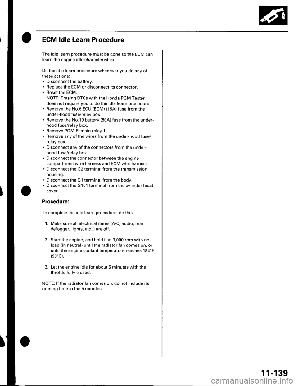
ECM ldle Learn Procedure
The idle learn procedure must be done so the ECM can
learn the engine idle characteristics.
Do the idle learn procedure whenever you do any of
these actions:. Disconnect the battery.
Replace the ECM or disconnect its connector.
Reset the ECM.
NOTE: Erasing DTCS with the Honda PGM Tester
does not require you to do the idle learn procedure.
Remove the No.6 ECU {ECM) ( 15A) fuse from the
under-hood fuse/relay box.
Remove the No.19 baftery (80A) fuse from the under-
hood fuse/relay box.
Remove PGM-FI main relay 1.
Remove any of the wires from the under-hood fuse/
retay Dox.
Disconnect any of the connectors from the under
hood fuse/relay box.
Disconnect the connector between the engine
compartment wire harness and ECM wire harness.
Disconnect the G2 terminal from the transmission
ho u srng.
Disconnectthe G'l terminal from the body.
Disconnectthe G101 terminal from the cylinder head
cover.
Procedure:
To complete the idle learn procedure, do this:
1. Make sure all electrical items (Ay'C, audio, rear
defogger, l:ghts, etc.,) are off.
2. Start the engine, and hold it at 3,000 rpm with no
load {in neutral) until the radiator fan comes on, or
until the engine coolanttemperature reaches 194"F(90'c).
3. Let the engine idle for about 5 minutes with the
throttle fully closed.
NOTE: lf the radiator fan comes on, do not include its
running time in the 5 minutes.
11-139
Page 366 of 1139
Intake Air System
Component Location Index
INTAKE AIR BYPASS CONTROLTHERMAL VALVETest, page 1'1-161
i l.
AIR CLEANERReplacement, page 1 1'162AIR CLEANER ELEMENTReplacement, page 1 1-162
THROTTLE CABLEAdjustment, page 1 1-163Removal/lnstallation, page 1 1-164THROTTLE BODYTest, page l'l-160Removal/lnstallation, page 1 1-165Disassembly/Reassembly, page 1 1 166
11-159
Page 367 of 1139

Intake Air System
Throttle Body Test
NOTE:. Do not adjust the throttle stop screw. lt is preset at the
factory.. lf the malfunction indicator lamp (MlL) has been
reported on, check for diagnostic trouble codes(DLCS) (see page 11 3).
1. With the engine off, check the throttle cable
movement. The cable should move without binding
or sticking.
. lf lhe cable moves OK, goto step 2.. lf the cable binds or sticks, check it and its routing.. lf the cable isfaulty, reroute itor replace itand
adjust it (see page 11-163), then go to step 2.
2. l\4ove the throttle lever by hand to see if the throftle
valve and/or shaft are too loose or too tight.
. lf there is excessive play in the throttle valve
shaft, or any binding in the throttle valve at the
fully closed position, replace the throttle body.. lf thethrottlevalve and shaft are OK, goto step3.
3. Connect the scan toolto the DLC.
Turn the ignition switch ON (ll).
Check the throttle position with the scan tool. The
reading should be about 10% when the throttle is
fully closed and about 90% when the throttle is fully
openeo.
. lf the throttle position is correct, the throttle body
is OK.. lf thethrottle position is notcorrect, replace the
throttle body.
5.
11-160
!