Page 815 of 1139

Heating and Air Conditioning
Heater Unit/Core Replacement (cont'd)
8. Remove the dashboard {see page 20-66).
9. Disconnectthe connectors (A) from the blower
motor, the recirculation control motor, the mode
control motor, and the power transistor, then
remove the wire harness clips (B) and the
connector (C). Remove the self-tapping screws and
the bracket (D).
Disconnect the connectors (A) from the evaporator
temperature sensor and the air mix control motor,
then remove the wire harness clips (B) and the
connector (C). Remove the self-tapping screw and
the cover (D). Disconnect the heater valve cable (E).
10,
7t,
21-44
11. Remove the mounting bolts, the mounting nuts,
and the heater unit.
Remove the self-tapping screws and the expansion
valve cover (A). Carefully pull out the evaporator
core (B) so you don't bend the inlet and outlet pipes.
Remove the grommet (C), then remove the self-
tapping screws and the flange cover (D). Bemove
the self-tapping screws and the pipe cover (E), then
carefully pull out the heater core (F) so you don't
bend the inlet and outlet oioes.
@
5x 1.0 mm9.8 N.m11.0 kgl m,7.2 tbf.ftl
12.
Page 829 of 1139

Heating and Air Conditioning
A/C System Tests (cont'd)
1.
Performance Test
Air conditioning refrigerant or lubricant vapor
can irritate your eyes, nose, or throar.
Be carefulwhen connecting service equipment.
Do not breathe refrigerant or vapor.
The performance test will help determine if the air
conditioner system is operating within specifications.
Use only service equipment that is U.L.-listed and is
cenified to meet the requirements of SAE J2210 toremove HFC-134a (R-134alfrom the air conditioning
system.
lf accidental system discharge occurs, ventilate the
work area before resuming service
R-134a service equipment or vehicle air conditioning
systems should not be pressure tested or leak testedwith compressed air.
Additional health and safety information may be
obtained from the refrigerant and lubricant
manufacturers.
Connect a R-134a refrigerant recover/recycling/
charging station to the high-pressure service port
and the low-pressure service port, following the
equipment manufacturer's instructions.
Determine the relative humidity and air
Iemperaru re.
' Compressed air mixed with R-134a forms a
combustible vapor.. The vapor can burn or explode causing serious
Injury.. Never use compressed air to pressure test
R-134a service equipment or vehicle air
conditioning systems.
21-58
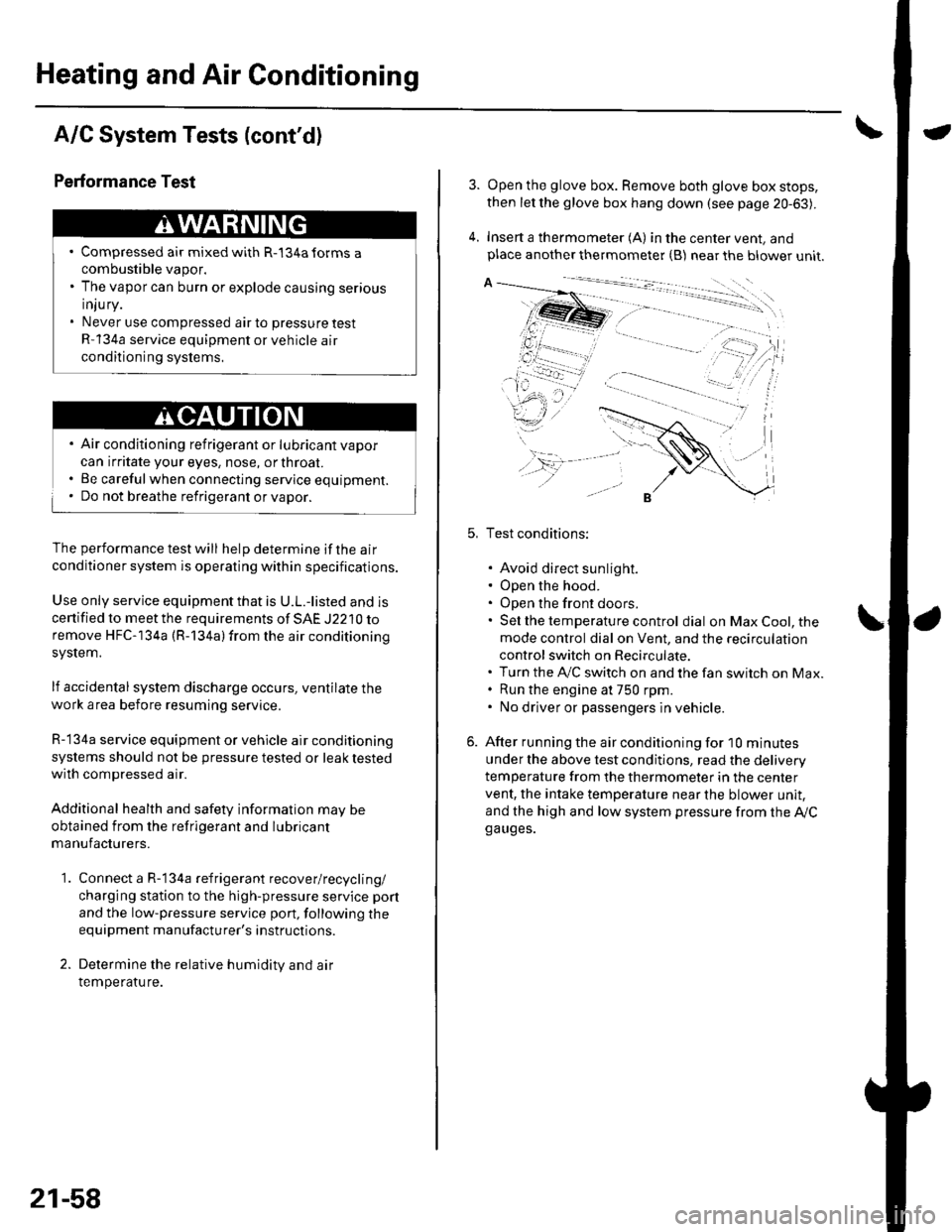
4.
Open the glove box. Remove both glove box stops,
then let the glove box hang down (see page 20-63).
Insert a thermometer (A) in the center vent, andplace another thermometer {B) near the blower unit.
Test conditions:
. Avoid direct sunlight.. Open the hood.. Open the front doors.. Sel the temperature control dial on Max Cool, the
mode control dial on Vent, and the recirculation
control switch on Recirculate.. Turn the A,/C switch on and the fan switch on Max.. Run the engine at 750 rpm.. No driver or passengers in vehicle.
After running the air conditioning for I0 minutes
under the above test conditjons, read the delivery
temperature from the thermometer in the center
vent, the intake temperature near the blower unit,
and the high and low system pressure from the Ay'Cga uges.
Page 874 of 1139
A/C Wire Harness
Connoctor or TerminalRelCavitiesLocationConnec'tstoNotesAir mix control motorBlower motorEvaporator temperature sensorMode control motorPowertransistorRecirculation control motorc851
c852
c853
I283411
6
5
52210
51
21
,]
Under maddle of dashUnder right side of dashUnder middle of dashUnder right side of dashUnder right side of dashUnder right side of dashUnder middle ol dash
Under middle ofdash
Under middle o{ dash
Engine compartment wireharness (see page 22-18)Dashboard wire harness A{see page 22 26iDashboard wire harness Alsee oaoe 22-261
22-43
Page 878 of 1139

Under-dash Fuse/Relay Box
Fuse
Number
AmpsWire ColorComponent(s) or Circuit(s) Protected
115ABLKA/VHTlgnition coils
2204WHT/REDAirlfuel ratio sensor, ECM
310ARED/BLUDaytime running Iights control unit {Canada)10ABLI(ORNAir/fuel ratio sensor relay, Alternator, CMP sensor, Cruise control main
switch, Cruise control unit. ELD unit, Evaporative emission (EVAP) bypass
solenoid valve, Evaporative emission (EVAP)canister purge valve,
Evaporative emission (EVAP) canister vent shut valve, Secondary H02S,
Vehicle speed sensor
5Not used
67.5AYEUGRNMoonroof control unit, Moonroof open and close relay, Power window
relaV
7204GRNMoonroof motor
I7.5AYEUREDAudio unit
910AGRNOPDS unit, Rear window wiper motor, Rear window washer motor, Rear
window wiper intermittent control unit
107.54YELBack-up lights, Cruise indicator light, EPS control unit, Gauge assembly,
Keyless receiver unit, Multiplex control unit, Security control unit
connector (optional)
117.5ABLIVORNABS modulator-control unit
127.5AYEUREDDaytime runnino liohts control unit (Canada)
1310APNKSRS unit't410ABLK/YE LA,,/C compressor clutch relay, Blower motor relay, Condenser fan relay,
Heater control panel, Power mirror actuator, Power mirror defogger(Canada), Radiator fan relay, Rear window defogger relay, Recirculation
control motor1ENot used
loNot used
1715AYE L/B LKECM, Fuel pump
B LK/YE L>H> Unrr
1815AYEUGRNAccessory power socket
197.5AYEUBLKTurn siqnal/hazard relav, Turn siqnal liohts
2030AGRN/BLKMultiplex control unit, Windshield washer motor. Windshield wioer motor21Not used
22204GRN/BLKPassenqer's window motor
2320A.G R N,A/VHTDriver's window motor
24Not used
25Not used
__^:Hr tl_l
f at-t
at I
r^,rl fl
!!;r -
!339,i;s!!sf Fnf : |rnITf
22-47
Page 1138 of 1139

Service Manual lndex
(cont'dl
Power Window Switch, Passenger'slnput Test .............-......
Replacement...,-.-.-...,..
Radialor Cap
Rocker Arm AssemblyRemovalD;sassembly/Reassembly
Specifications6-26 (See section 2)22-13022 13222-133..................... 6-27
ComponentLocation Index ..............22 124Circuit Dia9ram .................. ............... 22 125
Ouaner Window Glass8ep1acement ......................................... 20-29
lnstallation6-38
Rocker ArmsTestInspecton6-28
Roof MoldingsReplacement
Seat BeltsComponent Location Index ................... 23-3
Seat 8ehs, FrontReplacementrnspec!on
sRsComponent Location Index ................. 23-13Description ....................................... 23-31Circuit D;agram ... .... ...........2334lnspection/Replacemenl ................... 23 1 126-7
SRS lndicator CircuilTroubleshooting
Startel
Stabilizer BarReplacementFront SuspensionRear Suspension
Stabilizer LinksRemoval/lnstallationFront SuspensionRear Suspension
23 105oSRS UnitReplacement..-.................................... 23-122s
R
1A-1718-30
18 1818-31RadiatorTest......23-9
23-1Replacement ...........
Radiator and Condenser FansCommon CircuitTroubleshooling......... ..... .........21 29
10-310-10Seat Behs, RearReplacement
Seat Cover, FrontReplacement
Seat Cushion Cover, R6ar10-3Replacement
ReplacementTest
Test
20-75
20-84
Overhaul
Starter SolenoidTest..-.-...4-7
Radiator Fan AssemblyTestSeat, Driver'sRemovaf/lnstaf lation ............................ 20 1 1Disassembly/Reassemb1y ................... 20-73
Sedt, Faont Passenger'sDisassembly/Reassemb1y ................... 20-74
Seat, RearRemoval/lnstallation ............................ 20-80
Seat-back Cover, Reer
Starting SystemComponent Location Index...............-..... 4-3CircuitDia9ram ........................................ 4 4
\'{........................ r0-4
Radiator Fan CircuitTroubleshooting
Radiator Fan SwhchReplacementTest
Radiator Fan Switch CircuitTroubleshooting
Rear Air OutletReplacement
Circuil DiagramTest
Rear Window D€rogger WiresRepair
RearWindow GlassReplacement
Troubleshooting10-14
10-1710-17
10 16
17 -3
11-4
17-9
SteeringComponent Location Index................-..Inspectaon ...................
Steering ColumnRemoval/lnstallationReplacementInspection11 11
17-5117 5517 63
20 68
Seat-back Latch, ReaI2Q-104Replacement
Seat-back Striker. RearReplacement
Steering GearboxRemovalOverhaulRear Window DefoggerComponentLocalion Index ..............22 104lnstallation
Steering Hanger BeamReplacement
Steering LinkageInspefiron
Steering LockReplacement
Steering Rack GuideAdiustment
22-10522 106
22-106
SeatsComponent Location Index....-............ 20-70
Shift ForksInspectton13,21
20-25
2l-3621 36
21 25
Disassembly/Reassembly ................... 13-22
Shitt Lever TrimRemoval/lnstallation ............................ 20 61
.....11-12
SecirculationReplacementControl Motor17-13Test.....
Recirculation Control Motor CircuitTroubleshooting
Side Airbag, Drivel'sReplacement
Side lmpact SensorsReplacement
Spark Plugs
23-115
23 123
Side Marker LightRep1acement......................................... 22-A3
17417-6Disassembly/Reassembly ..................... 17 71nsta11ation .............................................. 17-8
SublramesReplacement
Removal
RefrigerantReplacement ..-.-.-...................... 21 53, 54, 55Test ........................................................ 21-56
Retrigerant OilReplacement...............................-........... 21-6. .._..4_19
20 112
Page:
< prev 1-8 9-16 17-24