2003 HONDA CIVIC oil change
[x] Cancel search: oil changePage 411 of 1139

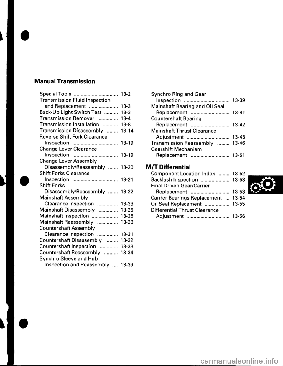
Manual Transmission
SpecialTools
Transmission Fluid Inspection
and Reo1acement ...................-.
Back-Up Light Switch Test ..........
Transmission Removal
Transmission Installation ...........
Transmission Disassemblv ........
Reverse Shift Fork Clearance
lnsoection
Change Lever Clearance
lnsoection
Change Lever Assembly
Disassembly/Reassembly .......
Shift Forks Clearance
Inspection
Shift Forks
Disassembly/Reassembly .......
Mainshaft Assemblv
Clearance Inspection
Mainshaft Disassembly
Mainshaft lnsoection
Mainshaft Reassembly
Countershaft Assemblv
Clearance Inspection
Countershaft Disassembly .........
Countershaft Inspection .............
Countershaft Reassembly ..........
Synchro Sleeve and Hub
Inspection and Reassembly ....
Synchro Ring and Gear
Insoection ....... 13-39
Mainshaft Bearing and Oil Seal
Replacement ........................,... 13-41
Cou ntershaft Bearing
ReDlacement .. 13-42
Mainshaft Thrust Clearance
Adiustment ..... 13-43
Transmission Reassemblv ......... 13-46
Gearshift Mechanism
Replacement ............................ 13-51
M/T Differential
Comoonent Location Index ........ 13-52
Backlash Inspection ..................... 13-53
Final Driven Gear/Carrier
Replacement .. 13-53
Carrier Bearings Replacement ... 13-54
Oil Seal Replacement .................. 13-55
Differential Thrust Clearance
Adiustment ..... 13-56
13-2
| 5-J
tJ-5
13-4
I J-at
13-14
13- 19
13- 19
13-20
13-21
13-22
13-23't3-25
13-26
| 5-2.5
13-31
13-32
13-33
13-34
13-39
Page 413 of 1139

Transmission Fluid Inspection and
Replacement
'1. Park the vehicle on level ground, and turn the
engine OFF.
2. Remove the oilfiller plug (A) and washer (B), check
the condition of the fluid, and make sure the fluid is
at the proper level (C).
lf the transmission fluid is diny, remove the drain
plug (D) and drain the fluid.
A44 N.m{4.5 kgt.m,33 rbr.ftl
Reinstall the drain plug with a new washer, and
refill the transmission fluid to the proper level.
Oil Capacity
1.5 0 (1.6 US (F) at tluid change
1.7 0 {1.8 US qt) at overhaul
Always use Honda Manual Transmission Fluid
(MTF). Using motor oil can cause stiffer shifting
and noise because it does not contain the proper
additives.
Reinstall the oil filler plug with a new washer.5.
13-3
Back-Up Light Switch Test
1. Disconnectthe back-up light switch (A) connector.
Check for continuity between the back up light
swilch 2P connector No. 1 and No.2 terminals.
There should be continuity when the shift lever is in
reverse.
lf necessary, replace the back-up light switch.
Apply liquid gasket (P/N 08718-0001), and install it
on the transmission housing.
2.
3.
Page 425 of 1139

o,. @\
'\b
e
P\B
z-W
-
€:
iq { "
Exploded View-Transmission Housing
@------
tt-P
"=-@
{i) 80 mm SHIM
0 8 x 14 mm DOWEL PIN
[A CHANGE LEVER ASSEMBLY
a0 6 mm FLANGE BOLT12 N m {1.2 kgf.m,9 lbf ft}
O DETENT BOLT22 N.m {2.2 kgf.m, 16lbf.ft)
O 12 mm waSHERReDlace.
(D SPRING
[I STEEL BALL(D TRANSMISSION HANGER B(9 CLUTCH LINE CLIP BRACKET
@
rai\€:/
o
f/
dd
\@
O=-rlF,z
O TRANSMISSION HOUSING
O 10 mm WASHERReplace.
@ 10 mm FLANGE BOLT44 N.m {4.5 kgf.m,33lbf.ft)
O 8 mm FLANGE BOLT27 N.m 12.8 kgf m,20lbl.ft)
.' TRANSMISSION HANGER A
O INTERLOCK BOLT39N m (4.0ksf.m,29lbf.ft)
O OIL GUIOE PLATE M
€.1 72 mm SHIM
.' OIL GUTTEB PLATE
,-1 _\(g/----------__-
"^\
\-/r*---------..-,
@) 20 mm WASHERReplace.
q,] FILLER PLUG44 N m {4.5 kgf.m,33 lbf.ft)
@ 40 x 56 x 8 mm OILSEALReplace.
qO 14 mm WASHERReplace.
q' DRAIN PLUG39 N.m (4.0 kgf.m,29 lbf.ftl
@ 32 mm SEALING CAP34 N m (3.5 kgf.m, 25 lbf.ft)
o
(cont'd)
13-15
Page 430 of 1139

Manual Transmission
Change Lever Assembly Disassembly/Reassembly
Prior to reassembling, clean all the parts in solvent, dry them, and apply lubricant to any contact surface.
BREATHER CAPTurn the arrow toward the {ronto{ the vehicle, and install it.
SELECT LEVERBe careful not to damage the dust sealwhen installing it.@).1 IlLrl
rrl
I
DUST COVEB
a^^
7 Fr"irr6-rooa
(P/N 08798-9002)
ROLLER
6x1.0mm12 N.m(1.2 kgl.m,8.7 lbf.ft)
'^ E-='-Fl !-d 1sr/2Noq )-=^l sELEcr
i €2 sPntruc
,.* (A)tace. ix�#,,l
H\
lV srxSELECT-z:-=:l-': SPRING
r\
tr7
,/u
/
\op
(g)'
' -, OIL SEAL,/ ReDlace./-r,s
\__/
INTERLOCK
SHIFT ARM
SELECT STOPPLATE
REVERSE LOCK CAMSTRIKER
SHIFT ARM COVER
WASHER
9.8Nm{1.0 kgf.m, 7.2 lbf.ft)
13-20
Page 459 of 1139

16. Remove the dirt and oil from the shift iever cover
sealing surface. Apply liquid gasket (P/N 08718-
0001) to the sealing surface.
NOTE: lf 5 minutes have passed after applylng
liquid gasket. reapply it and assemble the housings.
Allow it to cure at least 20 minutes after assembly
before filling the transmission with oil.
- - -Liquid gasket
17. Installthe 8 x 14 mm dowel pins (A). clutch line clip
bracket (B), and change lever assembly (C).
12 N.m (1.2 kgf.m,9lbt ft)
18. Apply liquid gasket (Pi N 08718-0001) to the threads
of the interlock bolt (D), and install it on the
transmission housing.
6x1.0mm
19. Installthe drain plug (A), filler plug (B), and 10 mm
flange bolt (C) with new washers.
A39Nm(4.0 kgf m,33 tbl.ft)
20.
/..l-.=,'-Bg ^ 44N.m
@ Ut !?iJl'.'l,''
R\-: \
-.-t ?0, ,.ru ^44 N m {4.5 kgt m,33lbf.ft}
Installthe detent bolts (A), spring, and steel balls
with new washers.
{3.0 kgf.m.22lbf.ft)
Apply liquid gasket {P/N 08718-0001}to the threads
oithe back-up light switch (B), and install it in the
transmission housing.
(cont'd)
21.
13-49
Page 635 of 1139

t
Wheel Sensors
The wheel sensors are the magnetic contactless type. As the gear pulser teeth rotate past the wheel sensor's magnetic
coil, AC current is generated. The AC frequency changes in accordance with the wheel speed. The ABS control unit
detects the wheel sensor signal frequency and thereby detects the wheel speed.
!t LOW SPEED
Wheel Speed and Modulator Control
8E!EEETqE VEJ!q!ESPEEq
5
PRESSURE
OUTLETVALVE 9p
OFF
INLETVALVE oN
OFF
MoroR I-,. ltlOFF
When the wheel speed drops sharply below the vehicle speed, the inlet valve closes and il necessary, the outlet valve
opens momentarily to reduce the caliper fluid pressure. The pump motor starts at this time. As the wheel speed is
restored, and the outlet valve closes, the inlet valve opens momentarily to increase the caliper fluid pressure.
GEAR PULSERWHEEL S€NSOR.r HIGX SPEED
19-41
Page 784 of 1139

Heating and Air Gonditioning
System Description (cont'dl
The air conditioning system removes heat from the passenger compartment by circulating refrigerant through the
system as shown below.
/
BLOWER FAN
\
\,u
EXPANSION VALVE(Meters the requiredamount of refrigerantinto the evaporator)
A/C PRESSURE SWITCHWhen the refriqerant is below196 kPa (2.0 kgi/cm',28 psi)or above 3,140 kPa (32 kgf/cm'455 psi), the Py'c pressureswitch opens the circuit tothe Py'C switch and stops theair conditioning to protect thecompressor-
RECEIVER/DRYER(Traps debris, andremoves morsturel
APOBATOR TEMPERATURESENSOR
THERMAL PROTECTOR(Opens the compressor clutch circuitwhen the compressot temperaturebecomes too high)
RELIEF VALVE(Relieves pressure at the compressorwhen the pressure is too high)
A/C COMPRESSOR(Suction and comoression)\-^
I HrcH PRESSURE vAPoR
[ '.... -:--l Low PREsSUBE LrourD
tffi Low PREssURE vAPoR
This vehicle uses HFC-134a (R-'134a) refrigerant which does not contain ch lorofluorocarbons. Pay attention to the
following service items:
. Do not mix refrigerants CFC-12 (R-12) and HFC-134a (R-134a). They are notcompatible.. Use onlythe recommended polyalkyleneglycol (PAG ) refrigera nt oil (KElHlN SP '!0) designedfortheR-134a
compressor. Intermixing the recommended (PAG) refrigerant oil with any other retrigerant oil will result in
compressor failu re.. AllAy'C system parts (compressor, discharge line, suction line, evaporator, condenser, receiver/dryer. expansion
valve, O-rings for joints) have to be designed for refrigerant R 134a. Do not exchange with R-'12 parts.
. Use a halogen gas leak detector designed for refrigerant R-134a.. R-12 and R-134a refrigerant servicing equipment are not interchangeable. Use only a recovery/recycling/charging
station that is U.L.-listed and is certified to meet the requirements of SAE J2210 to service R-134a air conditioning
system.. Always recover the refrigerant R-134a with an approved recovery/recycling/charging station before disconnecting
any Ay'C fifting.
/-
CONDENSER(Radiation of heat)
21-12
Page 1137 of 1139

)
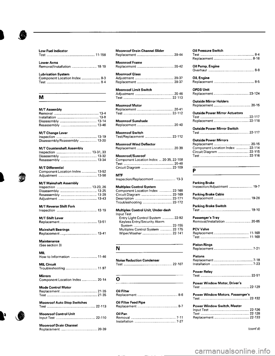
Low Fuel lndicatorTest.....................11-158Moonroof Drain Channel SliderReplacement......................................... 20'44
Moonroof FrameRep1acement,,,,,,,,,,.,.,.,.,.,.,.,,,,,,............ 20 42
MoonroolGlassAdiustment ........................................... 20-37Rep1acement......................................... 20 37
Moonroot Limit SwitchAdjustment ........................................-.- 20 46Test ...................................................... 22 113
Moonrool MotorReplacement....-.................................... 2D-41
Oil Pressure SwitchTest ................-.-........-................................ 8-4Replacement.........-................................. 8-16
Oil Pump, EngineOverhau1 ................................................... 8-8
Oil, EngineReplacement...-................-.-...................... 8-5
OPDS UnitReplacement....................................... 23- 124
Outside Mirror HoldersBeplacement......................................... 20-15
Outside Power Mirror ActuatorsTest ...................................................... 22-117Bepf acement..-.................................... 22-1 14
Outside Power Mirror SwitchTest ..-................................................... 22-111
Outsid€ Power MirrorsReplacement............................ ... .. . . . 20-15Component Location lndex .............. 22- 114Circuit Diagram .................................. 22-115Test -..................................................... 22-116
Lower ArmsRemoval/1nsta11ation............................ 18 19
Lubrication SystemComponent Location Index..................... 8-3Test............................................................ 8 4
M
M/TAssemblyRemoval.......... 13-4 Test...................... 22-1 12lnstallation............. 13-8
.........21,35
Disassembly ......................................... 13-14Resassembly .. ... ................. 13-46
M/TChange Leverlnspection ............................................. 13-19Disassembly 8eassemb1y ................... 13-20
M/T Countershaft AssemblyInspection ....................................... 13 31, 33Disassemb1y ......................................... 13-32Resassemb|y ........................................ 13-34
M/T DifferentialComponentLocation Index................. 13-52Adiuslment ........................................... 13-56
M/T Maifthaft Assembly1nspection ... ................................... 13-23, 26Disassembly ......................................... 13 25Resassembly ........................................ 13 28Adjustment ........................................... 13-43
M/T Reverse Shift ForkInspection .................... ........................ l3 19
M/T Shift LevelReplacement......................................... 13-51
Mainshaft BearingsReplacement....,.................................... 13 41
MairtenancelSee section 3)
MILHow to Informatron ............................. 1 1.46
MIL CircuitTroubleshooting .......... .- . . . . ......... 11 97
MirrorsComponentLocation Index................. 20'14
Mode Control MotorReplacement
Moonrool SunshadeRep1acement....................... . . ............. 20 40
Moonroof SwitchTesVRep1acement .............................. 22- l 12
Mooniool Wind Def lectorReplacement.......................-................. 20-38
Moonroof/SunroofComponent Location Index ... 20-35, 22-108Test ........................................................ 20-48Cf rcuit Diagram .................................. 22- 109
MTFInspection/Rep1acement. .......... ........... 13-3
Muhiplex Control SystemComponentLocation lndex ..............22 168Circuit Diagram .................................. 22-1690escription ......................................... 22-17 1Troubleshooting ................................ 22-17 2
Muliiplex Control Unit, Under-dashInput TestEntry Light Control Sysiem ............. 22-92Keyless Entry/Security AlarmSystern .-....................................... 22-155MultiplexControl System .............22 115Wiper/Washer................................. 22'1 41
NoiseTest,,Reduction Condenser
Parking ErakeInspection Adjustment ........... .............. 19-7
Parking Brake CableRep1acement......................................... 19-26
Parking Erake Switch
P
l
Test ...................... 19-10
Test............................... . ...........2135
Moonroof Auto Stop SwitchosTest ...................................................... 22'113
Moon.oot Control Unillnput Test ............................................ 22-110
Moonroof Drein ChannelBeplacement ... . ....... ......................... 20 39
Oil Filte]Replacement............................................. 8-6
Oil Filter Feed PipeReplacement............... . ..-,...,.,,,,,,,,8-7
Oil PanRemoval .............,.,,,,,,,,,,,,.,.,,,.........-....... 7 1 1lnstallation .............................................. 7 -27
Passenger's TraVRemoval/lnstallation ............................ 20-65
PCV ValveBeplacement....................................... 1 1'169Test........................................... l1 169
Piston Rings8ep1acement................................-.-...-.- 7-21
PistonsReplacement...................-....................... 7-181nsta|1ation ...................................... ...1-23
Power R€layTest ...............-.-...................................... 22-51
Power Window Motor, Driver'stesl.....,,,, .,.,,,............
Power Window Motors, Passenger's
Power Window Switch, Masterlnput Test ..........-.........-....................... 22-126Tesr ....... . ............................................ 22 124Replacement....................................... 22-133
N
..............22 101
o
l' ,e
(cont'd)