Page 929 of 1139
Audio System
Component Location Index
AUOIO UNITRemoval/f nstallation, Daoe 22-100Connector Terminals, pa-ge 22-101
RIGHT DOOB TWEETERReplacement, page 22-102
ANTENNA SUB LEAD
DRIVER'S DOOR SPEAKERReplacement, page 22 102
ROOF ANTENNAReplacement, page 22-'1 03
RIGHT REAR SPEAKERReplacement, page 22-102
LEFT REAR SPEAKERReplacement, page 22-102
ANTENNA LEAD
22-98
Page 930 of 1139
tCircuit Diagram
' No.20ioA) :USA
/ 8AT \--------F f!t- WHT/FED ACC /
ACC HoTinACC lllmd0N llll
AUDIO UflIT
t-ra-r:-raOe?a
DRIVER'SDOORSPEArcFIEFITWEETERPASSE!{GIF'S SIGIITTWEETEBDOOB SPEAKESLEFTFEAB NrcBTREAFSPEA(I8 SPEAKEF
22-99
Page 931 of 1139

Audio System
Audio Unit Removal/lnstallation
NOTE:. Put on gloves to protect your hands.. Take care not to scratch the dashboard and relatedpa rts.
1. Make sure you have the anti-theft code for the radio,
then write down the frequencies for the radio's
preset buttons.
2. Remove the driver's dashboard lower cover (see
page 20-59).
3. Remove the two mounting bolts, then pull out the
center panel (A).
4.Disconnect the audio connector (B) and antenna
lead (C), heater control panel connectors (D) and
HAVC push switch assembly (E), then remove the
center panel.
22-100
!\,
7.
Remove the heater control panel (see page 21 38).
Remove the four mounting bolts and the audio unit
from the radio brackets.
Installthe audio unit in the reverse order of
removal, and note these items:
. Make sure the audio unit and A/C connectors areplugged in properly, and the antenna lead is
connected properly.. Enter the anti-theft code for the radio, then enter
the customer's radio station presets.
\v
I
Page 932 of 1139
Audio Unit Connector Replacement
CavityWireConnects to
1YEUG RNRoof antenna
2YEUREDACC (Power)
3Not used
4Not used
5PNKRioht rear sDeaker (+I
6BLU^/vHTLeft rear sDeaker (+)
7GRN/YELFront oassenqer's door sDeaker {+)/Riqht tweeter (+)
8G RN/BLKDriver's door speaker { + )/Left tweeter (+ )
9RED/BLKLiqhts on siqnal
10WHT/REDConstant power
11Not used
12Not used
Not used
14Not used
taB LU/YE LRioht rear soeaker (-
toBLU/BLKLeft rear sDeaker (
11GRY/REDFront passenqer's door speaker ( )/Riqhttweeter {
18LT GRNDriver's door sDeaker ( )/Left tweetr ( -
19REDDash liqhts briqhtness controller
20BLKG round (G503)
AUDIO UNIT 2OP CONNECTOR
22-101
Page 933 of 1139
Audio System
Speaker Replacement
Door Speaker:
1. Remove the door panel (seepage20-4).
2. Pull the top of the speaker {A) straight out, just
enough to release the upper clip. lf you pull the
speaker out too far, you will damage the lower clips(C). Then lifi the speaker straight up to release the
lower clips.
3. Disconnect the 2P connector (B), and remove the
speaKer.
Tweeter:
Carefully pry the tweeter (A) out of the mirror mount
cover, then disconnect the 2P connector (B) from the
tweeter.
'-----d
22-102
Rear:
1.Remove the speaker cover (A).
Remove the three screws, then disconnect the 2P
connector (B) from the speaker (C).
2.
Page 984 of 1139
Keyless Receiver Unit Input Test
1. Remove the driver's dashboard lower cover (see page 20-59).
2. Remove the audio unit (see page 22-100).
3. Disconnect the 5P connector (A)from the keyless receiver unit (B).
WHT/RED
Wire side of female terminals
4. Inspecttheconnectorandsocketterminalstobesuretheyareall ma king good contact.
. lf the terminals are bent. Ioose orcorroded, repairthem as necessary, and recheckthe system.. lf the terminals are OK, go to step 5.
l
(cont'd)
t
22-153
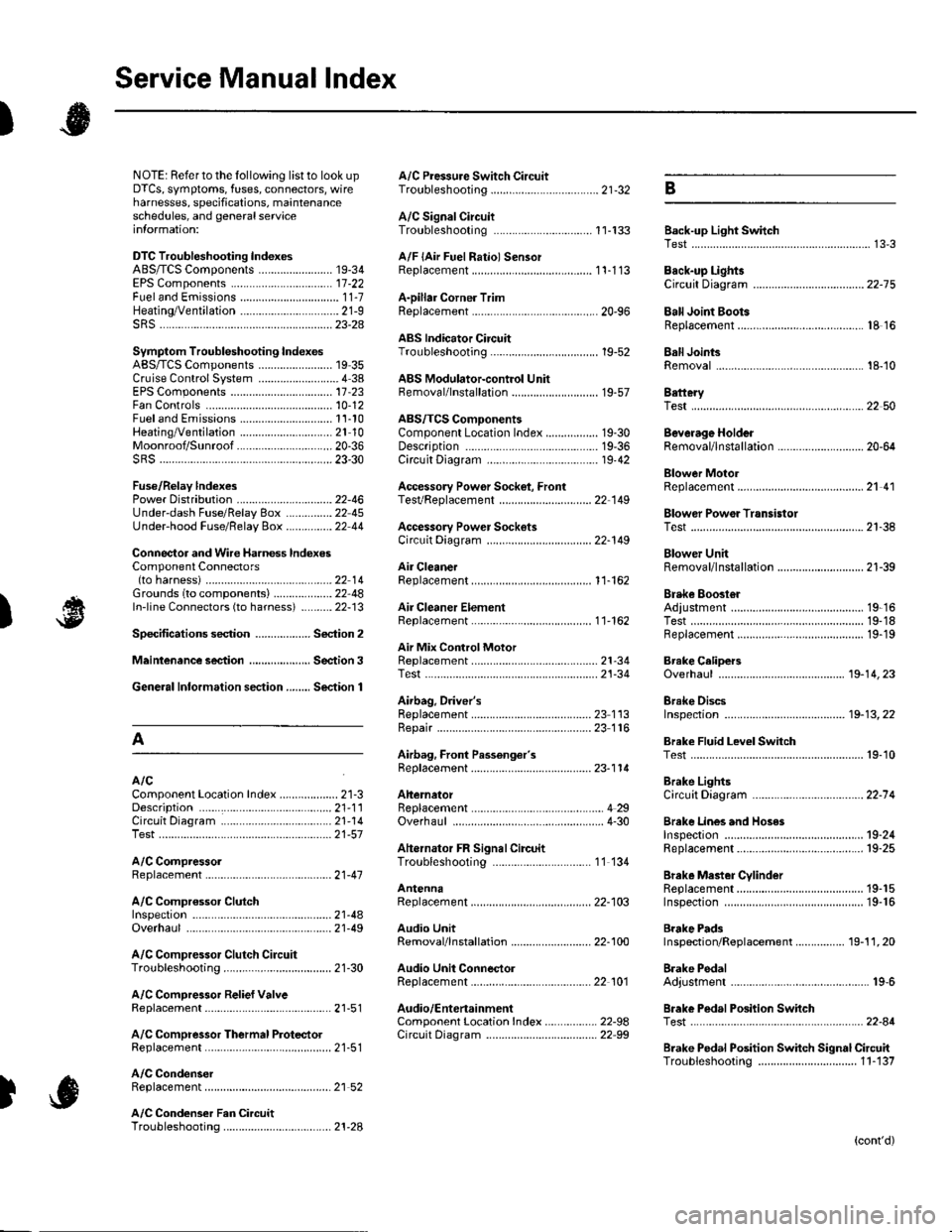
Page 1133 of 1139

Service Manual lndex
)s
NOTE: Referto the lollowing listto look up A/C Pressure Switch CircuitDTCS, symptoms, fuses, connectors, wire Troubleshooting ......... ...-.-....-...-.-.-....-..21-32 Bharnesses, specifications, maintenanceschedules, and general serviceinlormation:
DTC Troubleshooting Indexes
A/C Signal CircuitTroubleshooting.........................-...... 11-'133 Back-up Light SwitchTest .......................................................... 13'3A/F lAir Fuel Ratiol SensorABS/TCS Components ........................ 19-34 Replacement ....................................... 1 1-113 Back-up Li9ht3EPS Components ................................. '17-22 Circuit DiagramFueland Emissions11-i A-Dillar Corner Trim
ABS Indicator Circuit
Heating/Ventilation ................................ 21-9 Replacement ...............-.....-..............-.... 20,96 Ball Joint BootssRS ........................................................ 23-28Replacement ......
... 19-52 Ball Joints
22-75
18 16
Remova1.............-.......... . ...........18-10Symptom Troubleshooting Indexes TroubleshootingABS/TCSComponents........................ 19 35Cruise Control System ..........................4 38 ABS Modulator-contml UnitEPS Components ................................. 17-23 Bemoval/lnstallation ............................ 19-57 BettervFan Controls10,12
Accessory Powor Socket Front
Blowor Pow€r Transistor
.......22 50
Blower UnitRemoval/lnstallation ............................ 21-39
Fuel and Em issions .............................. 11-10 ABS/TCS ComoonentsHeating/Ventilation..............................21 10 Component Location Index ................. 19-30 Beverage Holder
SRS ........................................................ 23'30 CircuitDiaqram.......................... 19'42Blower MotorReplacement .....21 41
21-38
Power 0istribution ...............................22-46 TesVReplacement .............................. 22'149Under-dash Fuse/Relay Box ............... 22 45Under-hood Fuse/Belay Box ...............22 44 Accessory Power Sockets
Fuse/Relay lndexes
(to harness)
Connector and Wire Harness lndexesComponent Connectors
Circuit Oiagram .................................. 22-149
Air Cleaner......2214 Rep1acemen1.....................................11-162
Air MixControl MotorMeintenence section .................... Section 3 Replacement ......................................... 21'34 Brake CelipersTest......................21-34 Overhaul19-14,23Gene.al lnlormation section........ Section 1
21.57
Airbag. Driver's
Ahernator FR Signal CircuitTroubleshooting .... .........-..........11 134
AntennaReplacement
Inspection ............................................. 19-24Rep|acement................. .................... 19-25
Bieke Meder Cylinder
Irake Discs
A
Replacement ....................................... 23 1 'l3 Inspection .................... ................... 19-13,22Repair ...........-...................................... 23 1 16Brake Fluid Level SwitchAirbag. Front Passenger's TestBeplacement....................................... 23-1 14AIC Brake LightsComponent Location fndex ...................21-3 Altemator CircuitDiagram....................................22-74Description.....................................-....21'1'l Beplacement ................ ........................... 4 29CircuitDiagram....................................21-14 Overhaul .................................................4-30 Brake Lines and Hoses
19.10
A/C CompressolReplacement .......-...-............................. 21 -41
A/C Compr€ssor ClulchRep1acement......................................... 19-15.........22-103 Inspection ............................................. 19-16Inspecton........Overhaul ..........
A/C CondenserReplacement,.,
21-442l-49 Audio Unit
Replacement
Brake PadsRemoval/lnstallation .. ........................22-100 Inspection/Rep1acement................ 19-11,20A/C Compressor Clutch CircuitTroubleshooting ................................... 21-30 Audio Unit Connector Brake Pedal22101 Adjustment..............19,6ArfC Comoressor Relief ValvcReplacement ..........-...-.......................... 21-51 Audio/Entertainment
A/C Compr$sor Thermal Protector Circuit DiagramReplacement............-............................ 21-51
Component Location In dex .................22-9A Test .......-.............. 22-84Breke Pedal Posilion Switch
Brake Pedal Position Switch Signal Clrcuit11-137
.....21 52
A/C Condenser Fan CircuitTroubleshooting ................... . . . . . .....21-28
)s
Troubleshooting
(cont'd)