Page 934 of 1139
Roof Antenna Replacement
1. Remove the rear part of headliner (see page 20-54).
2, Disconnect the antenna lead connector (A) and 1P
connector (B) from the roof antenna (C).
3. Remove the mounting nut and the antenna.
22-103
Page 937 of 1139

Rear Window Defogger
Function Test
NOTE:. Be careful not to scratch or damage the defogger
wires with the tester probe.
. Before testing, check the No. 11 (30A) fuse in the
under-hood fuse/relay box and No. '14 ('10A) fuse in
the under-dash fuse/relay box.
1. Check for voltage between the ve rtica I dividersand
body ground with the ignition switch and defogger
switch ON.
There should be voltage as shown.
. lf there is no voltage. checkfor:- faulty defogger relay.- an open in the BLK, BLK,/YEL, or YEL/BLK wire.- taulty heater control panel.
. lf there is battery voltage, goto step 2.
6V
Check for continuity between the negative terminal(B) and body ground.
lf there is no continuity, check for:. an open in the BLK wire.. Poor body ground at the window antenna coil
mounting bolt.
Touch the voltmeter positive probe to the halfway
point of each defogger wire. and the negative
probe to the negative terminal,
There should be about 6 V with the ignition switch
and the defogger switch ON.
. lf thevoltage is asspecified, the defoggerwlre is
oK.. lf the voltage is not as specified, repair the
defogger wire.- lf it is more than 6 V, there is a break in the
negative half of the wire.- lf it is less than 6 V, there is a break in the
positive half of the wire.
2.
22-106
2.
Defogger Wire Repair
NOTE: To make an effective repair, the broken section
must be no longer than one inch.
1. Lightly rub the area around the broken section (A)
with fine steel wool, then clean it with alcohol.
Carefully mask above and below the broken portion
of the defogger wire (B) with transparent tape {C).
Mix the silver conductive paint thoroughly. Using a
small brush, apply a heavy coat of paint extending
about 1/8 inch on both sides of the break. Allow 30
minutes to dry.
Check for continuity in the repaired wire.
Apply a second coat of paint in the same way. Let it
dry 3 hours before removing the tape.
5.
Page 1133 of 1139

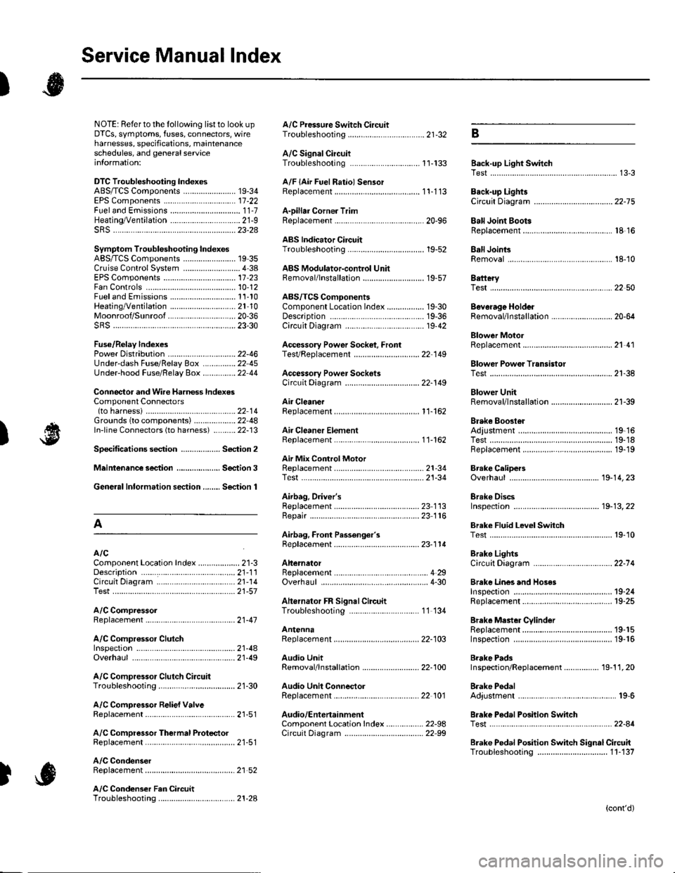
Service Manual lndex
)s
NOTE: Referto the lollowing listto look up A/C Pressure Switch CircuitDTCS, symptoms, fuses, connectors, wire Troubleshooting ......... ...-.-....-...-.-.-....-..21-32 Bharnesses, specifications, maintenanceschedules, and general serviceinlormation:
DTC Troubleshooting Indexes
A/C Signal CircuitTroubleshooting.........................-...... 11-'133 Back-up Light SwitchTest .......................................................... 13'3A/F lAir Fuel Ratiol SensorABS/TCS Components ........................ 19-34 Replacement ....................................... 1 1-113 Back-up Li9ht3EPS Components ................................. '17-22 Circuit DiagramFueland Emissions11-i A-Dillar Corner Trim
ABS Indicator Circuit
Heating/Ventilation ................................ 21-9 Replacement ...............-.....-..............-.... 20,96 Ball Joint BootssRS ........................................................ 23-28Replacement ......
... 19-52 Ball Joints
22-75
18 16
Remova1.............-.......... . ...........18-10Symptom Troubleshooting Indexes TroubleshootingABS/TCSComponents........................ 19 35Cruise Control System ..........................4 38 ABS Modulator-contml UnitEPS Components ................................. 17-23 Bemoval/lnstallation ............................ 19-57 BettervFan Controls10,12
Accessory Powor Socket Front
Blowor Pow€r Transistor
.......22 50
Blower UnitRemoval/lnstallation ............................ 21-39
Fuel and Em issions .............................. 11-10 ABS/TCS ComoonentsHeating/Ventilation..............................21 10 Component Location Index ................. 19-30 Beverage Holder
SRS ........................................................ 23'30 CircuitDiaqram.......................... 19'42Blower MotorReplacement .....21 41
21-38
Power 0istribution ...............................22-46 TesVReplacement .............................. 22'149Under-dash Fuse/Relay Box ............... 22 45Under-hood Fuse/Belay Box ...............22 44 Accessory Power Sockets
Fuse/Relay lndexes
(to harness)
Connector and Wire Harness lndexesComponent Connectors
Circuit Oiagram .................................. 22-149
Air Cleaner......2214 Rep1acemen1.....................................11-162
Air MixControl MotorMeintenence section .................... Section 3 Replacement ......................................... 21'34 Brake CelipersTest......................21-34 Overhaul19-14,23Gene.al lnlormation section........ Section 1
21.57
Airbag. Driver's
Ahernator FR Signal CircuitTroubleshooting .... .........-..........11 134
AntennaReplacement
Inspection ............................................. 19-24Rep|acement................. .................... 19-25
Bieke Meder Cylinder
Irake Discs
A
Replacement ....................................... 23 1 'l3 Inspection .................... ................... 19-13,22Repair ...........-...................................... 23 1 16Brake Fluid Level SwitchAirbag. Front Passenger's TestBeplacement....................................... 23-1 14AIC Brake LightsComponent Location fndex ...................21-3 Altemator CircuitDiagram....................................22-74Description.....................................-....21'1'l Beplacement ................ ........................... 4 29CircuitDiagram....................................21-14 Overhaul .................................................4-30 Brake Lines and Hoses
19.10
A/C CompressolReplacement .......-...-............................. 21 -41
A/C Compr€ssor ClulchRep1acement......................................... 19-15.........22-103 Inspection ............................................. 19-16Inspecton........Overhaul ..........
A/C CondenserReplacement,.,
21-442l-49 Audio Unit
Replacement
Brake PadsRemoval/lnstallation .. ........................22-100 Inspection/Rep1acement................ 19-11,20A/C Compressor Clutch CircuitTroubleshooting ................................... 21-30 Audio Unit Connector Brake Pedal22101 Adjustment..............19,6ArfC Comoressor Relief ValvcReplacement ..........-...-.......................... 21-51 Audio/Entertainment
A/C Compr$sor Thermal Protector Circuit DiagramReplacement............-............................ 21-51
Component Location In dex .................22-9A Test .......-.............. 22-84Breke Pedal Posilion Switch
Brake Pedal Position Switch Signal Clrcuit11-137
.....21 52
A/C Condenser Fan CircuitTroubleshooting ................... . . . . . .....21-28
)s
Troubleshooting
(cont'd)