2003 HONDA CIVIC service
[x] Cancel search: servicePage 1034 of 1139
I
Initializing the OPDS {Occupant Position Detection System} Unit
Special Tool Required
SCS service connector 07PAz-00'1 01 00
When a seat-back cover, seat-back cushion, and/or OPDS unit is replaced, initialize the OPDS by following theprocedure below.
NOTE: Make sure the front passenger's seat is dry. Set the seat-back in the normal position, and make sure there isnothing on the seat.
'1. l\4ake sure the ignition switch is OFF.
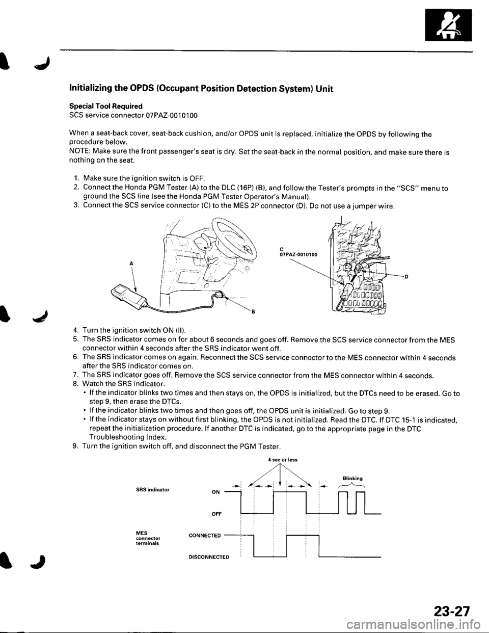
2. Connect the Honda PGM Tester (A) to the DLC (16P) (B), andfollowtheTester's prompts jn the ,,SCS,, menu toground the SCS line (see the Honda PGM Tester Operator's ManuaD.
3. Connect the SCS service connector (C) to the MES 2P connector (D). Do not use a iumoer wire.
c07PAZ-00r0100
4. Turn the ignition switch ON {ll).
5. The SRS indicator comes on for about 6 seconds and goes off. Remove the SCS service connector from the MESconnector within 4 seconds after the SRS indicator went off.
6. The SRS indicator comes on again. Reconnect the SCS service connector to the MES connector within 4 secondsafter the SRS indicator comes on.
7. The SRS indicator goes off. Remove the SCS service connector from the MES connector withln 4 seconds.8. Watch the sRS indicator.'lftheindicatorblinkstwotimesandthenstayson,theOPDSisinitialized.buttheDTCSneedtobeerased.Goto
step 9, then erase the DTCS..lftheindicatorblinkstwotimesandthengoesoff,theOPDSunitisinitialized.Gotostep9.
' lf the indicator stays on without first blinking.the OPDS is not initialized. Readthe DTC. lf DTC 15-'l is indicated,repeat the initialization procedure. lf another DTC is indicated, go to the appropriate page in the DTCTroubleshooting Index.
9. Turn the ignition switch off, and disconnect the PGM Tester.
SBS indic.ror
MES
IJ
DISCONNECTED
23-27
Page 1040 of 1139
Self-diagnosis System
A self-diagnosis circuit is built into the SRS uniU when the ignition switch is turned ON (ll), the SRS indicator comes onand goes off after about 6 seconds if the SRS is operating normally.
lf the indicator does not come on, or does not go off after 6 seconds. or if il comes on while driving, it indicates anabnormality in the SRS. The SRS must be inspected and repaired as soon as possible.
For better serviceability, the SRS unit memory stores a DTC that relates to the cause of the malfunction, and the unit isconnected to the data link circuit. This information can be read with the Honda PGM Tester when it is connected to thedata link connector (DLc) (see page 23-23).
23-33
Page 1118 of 1139
42. Turn the ignition switch OFF.
43. lf necessary, remove the SCS service connector
from the l\4ES connector.
44. Turn the ignition switch ON {ll}.
Does the SBS indicator come on for about 6
seconds and then go off?
YES -The system is OK at this time. t
NO Go to step 45.
45. Disconnect SRS unit connector C (8P) fromtheSRS
unit (see step 7 on page 23-221.
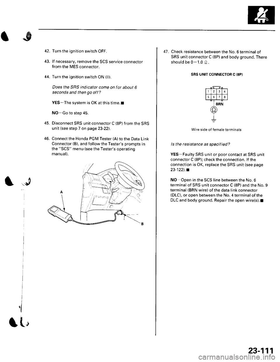
46. Connect the Honda PGM Tester {A) to the Data Link
Connector (B), and follow the Tester's prompts in
the "SCS" menu (see the Tester's operating
manu a l).
t .r9
I
,l
IL,
23-111
47. Check resistance between the No. 6 terminal of
SRS unit connector C (8P) and body ground. There
should be 0-1.0 Q.
SRS UNIT CONNECTOR C I8P)
Wire side of female terminals
ls the resistance as specified?
YES Faulty SRS unit or poor contact at SRS unit
connector C (8P); check the connection. lf the
connection is OK, replace the SRS unit (see page
23-1221..
NO Open in the SCS line between the No.6
terminal of SRS unit connector C (8P) and the No. 9
terminal (BRN wire) ofthe data link connector(DLC), or open between the No. 4 terminal of the
DLC and body ground. Repair the open wire(s).1
I2
50
BRN
n
Page 1122 of 1139
)Side Airbag Replacement
)
NOTE: Review the seat replacement pro6edure in the
Body section before pertorming repairs or service.
Removal
1. Disconnectthe battery negative cable, and wait atleast 3 minutes before beginning work.
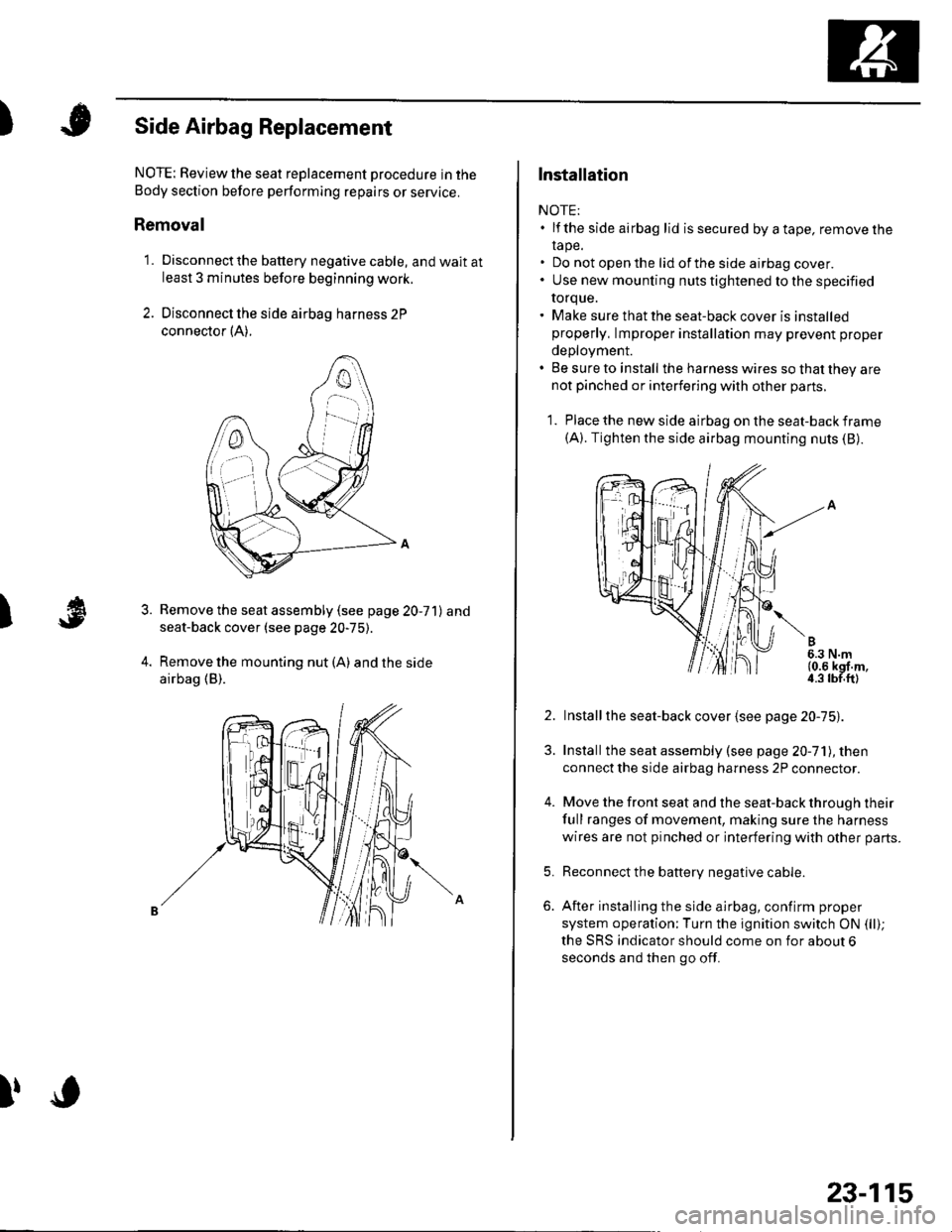
2. Disconnect the side airbag harness 2P
connector {A).
Remove the seat assembly (see page 20-71) and
seat-back cover (see page 20-75).
Remove the mounting nut (A) and the side
airbag (B).
3.
l,o
23-115
Installation
NOTE:. lf the side airbag lid issecured byatape, removelhe
rape.. Do not open the lid of the side airbag cover.. Use new mounting nuts tightened to the specified
torque.. Make sure that the seat-back cover is installedproperly, lmproper installation may prevent proper
deployment.. Be sure to install the harness wires so that they arenot pinched or interfering with other parts.
1. Place the new side airbag on the seat-back frame(A). Tighten the side airbag mounting nuts (B).
2. Installthe seat-back cover {see page 20-75).
3. Installthe seat assembly (see page 20-71), then
connect the side airbag harness 2P connector.
4. Move the front seat and the seat-back through their
full ranges of movement, making sure the harness
wires are not pinched or interfering with other parts.
5. Reconnect the battery negative cable.
6. After installing the side airbag, confirm proper
system operation;Turn the ignition switch ON (ll);
the SRS indicator should come on for about 6
seconds and then go off.
Page 1123 of 1139
sRs
Airbag Disposal
Special Tool Required
Deployment tool 07HAz-SG00500
Before scrapping any airbags, side airbags, seat belt
tensioners, or seat belt buckle tensioners (including
those in a whole vehicle to be scrapped), the airbags,
side airbags, seat belt tensioners, or seat belt buckle
tensioners must be deployed. lf the vehicle is still within
the warranty period, the Honda District Service
Manager must give approval and/or special instruction
before deploying the airbags, side airbags, seat belt
tensioners, or seat belt buckle tensioners. Only after the
airbags, side airbags, seat belt tensioners, or seat belt
buckle tensioners have been deployed (as the result of
vehicle collision, for example), can they be scrapped.
lf the airbags, side airbags, seat belt tensioners, and
seat belt buckle tensioners appear intact (not deployed),
treat them with extreme caution. Follow this Drocedure.
Deploying Airbags in the Vehicle
lf an SRS equipped vehicle is to be entirely scrapped, its
airbags, side airbags. seat belt tensioners. and seat belt
buckle tensioners should be deoloved while still in the
vehicle. The airbags, side airbags, seat belttensioners,
and seat belt buckle tensioners should not be
considered as salvageable parts and should never be
installed in another vehicle.
1. Turn the ignition switch OFF, then disconnect the
battery negative cable, and wait at least 3 minutes.
2. Confirm that each airbag, side airbag, or seat belt
tensioner is securely mounted.
3. Conf irm that the specia I tool isfunctioning properly
by following the check procedure on the tool label.
23-116
$J
Driver's Airbag:
4. Remove the access panel f rom the steering wheel,
then disconnect the driver's airbag 4P connector
from the cable reel (see step 2 on page 23-21).
Front Passenger's Airbag:
5. Lowerthe glove box, then disconnectthe front
passenger's airbag 4P connector from dashboard
wire harness B (see step 3 on page 23-211.
Side Airbag:
6. Disconnect the side airbag 2P connectors from the
floor wire harness (see step 4 on page 23-211.
Seat belt tensioner:
7. Disconnect the seat belt tensioner 2P connectors
from the floor wire harness {see step 5 on page 23-
22). Pull the seat belt out all the way, and cut it off.
Seat belt buckle tensioner:
8, Disconnect the seat belt buckle tensioner 4P
connectors from the floor wire harness (see step 6
on page 23-221.
Page 1125 of 1139
sRs
Airbag Disposal (cont'dl
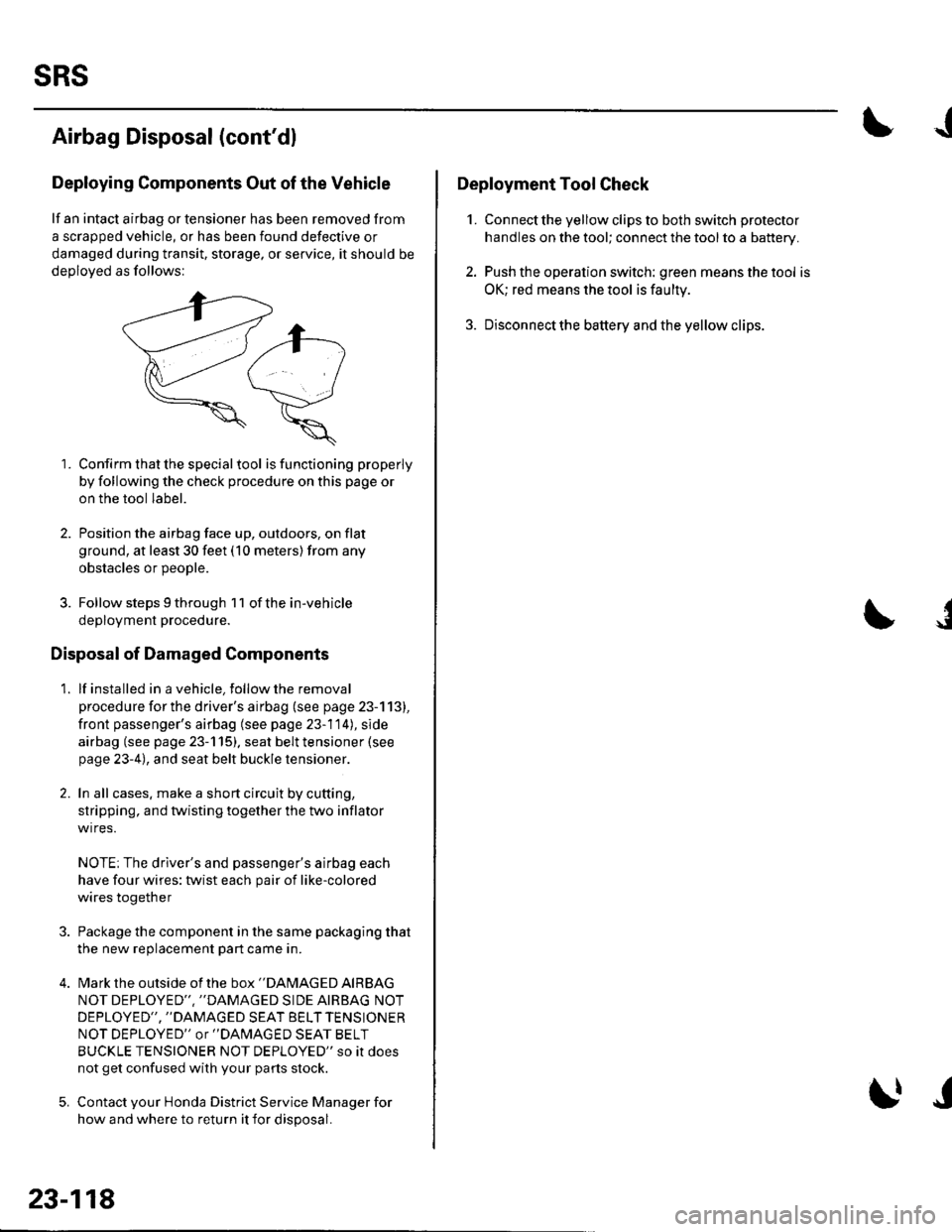
Deploying Components Out of the Vehicle
lf an intact airbag or tensioner has been removed from
a scrapped vehicle, or has been found defective or
damaged during transit, storage, or service, it should be
deoloved as follows:
1. Confirm that the special tool isfunctioning properly
by following the check procedure on this page or
on the tool label.
2. Position the airbag face up, outdoors, on flat
ground, at least 30 feet (10 meters) from any
obstacles or DeoDle.
3. Follow steps 9 through 1 1 of the in-vehicle
deployment procedure.
Disposal of Damaged Components
1. lf installed in a vehicle, follow the removal
procedure for the driver's airbag (see page 23-113),
front passenger's airbag (see page 23-114), side
airbag (see page 23-115). seat belt tensioner (see
page 23-4), and seat belt buckle tensioner.
2. In all cases. make a short circuit by cutting,
stripping, and twisting together the two inflator
wires.
NOTE; The driver's and passenger's airbag each
have four wires: twist each pair of like-colored
wires together
Package the component in the same packaging that
the new reolacement Dart came in.
Mark the outside of the box "DAMAGED AIRBAG
NOT DEPLOYED'" ''DAMAGED SIDE AIRBAG NOT
DEPLOYED", "DAMAGED SEAT BELT TENSIONER
NOT DEPLOYED" or "DAlvlAGED SEAT BELT
BUCKLE TENSIONER NOT DEPLOYED" so it does
not get confused with your parts stock.
Contact your Honda District Service Manager for
how and where to return it for disposal.
23-118
I|J
J
Deployment Tool Check
1. Connect the yellow clips to both switch protector
handles on the tool; connect the tool to a battery.
2. Push the operation switch: green means the tool is
OK; red means the tool is faulty
3. Disconnectthe battery and the yellow clips.
J
Page 1131 of 1139
sRs
OPDS Unit Replacement
NOTE: Review the seat replacement procedures in the
body section before performing repairs or service.
Removal
1. Disconnect the battery negative cable. and wait at
least 3 minutes before beginning work.
2. Disconnect the passenger's side airbag harness 2P
connector (see step 4 on page 23-2'll.
3. Remove the front passenger's seat assembly (see
page 20-71)and seat-back cover (see page2O-15],.
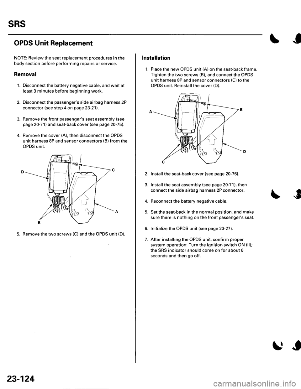
4. Remove the cover (A), then disconnect the OPDS
unit harness 8P and sensor connectors (B) from the
OPDS unit.
5. Remove the two screws (C) and the OPDS unit (D).
23-124
Installation
1. Place the new OPDS unit (A) on the seat-back frame.
Tighten the two screws (B), and connect the OPDS
unit harness 8P and sensor connectors (C) to the
OPDS unit. Reinstallthe cover (D).
2.
4.
1.
Installthe seat-back cover (see page 20-75).
Install the seat assembly (see page 20-71), then
connect the side airbag harness 2P connector,
Reconnect the battery negative cable.
Set the seat-back in the normal position, and make
sure there is nothing on the front passenger's seat.
Initialize the OPDS unit (see page 23-27).
After installing the OPDS unit, confirm proper
system operation: Turn the ignition switch ON (ll);
the SRS indicator should come on for about 6
seconds and then go off.
Page 1133 of 1139
Service Manual lndex
)s
NOTE: Referto the lollowing listto look up A/C Pressure Switch CircuitDTCS, symptoms, fuses, connectors, wire Troubleshooting ......... ...-.-....-...-.-.-....-..21-32 Bharnesses, specifications, maintenanceschedules, and general serviceinlormation:
DTC Troubleshooting Indexes
A/C Signal CircuitTroubleshooting.........................-...... 11-'133 Back-up Light SwitchTest .......................................................... 13'3A/F lAir Fuel Ratiol SensorABS/TCS Components ........................ 19-34 Replacement ....................................... 1 1-113 Back-up Li9ht3EPS Components ................................. '17-22 Circuit DiagramFueland Emissions11-i A-Dillar Corner Trim
ABS Indicator Circuit
Heating/Ventilation ................................ 21-9 Replacement ...............-.....-..............-.... 20,96 Ball Joint BootssRS ........................................................ 23-28Replacement ......
... 19-52 Ball Joints
22-75
18 16
Remova1.............-.......... . ...........18-10Symptom Troubleshooting Indexes TroubleshootingABS/TCSComponents........................ 19 35Cruise Control System ..........................4 38 ABS Modulator-contml UnitEPS Components ................................. 17-23 Bemoval/lnstallation ............................ 19-57 BettervFan Controls10,12
Accessory Powor Socket Front
Blowor Pow€r Transistor
.......22 50
Blower UnitRemoval/lnstallation ............................ 21-39
Fuel and Em issions .............................. 11-10 ABS/TCS ComoonentsHeating/Ventilation..............................21 10 Component Location Index ................. 19-30 Beverage Holder
SRS ........................................................ 23'30 CircuitDiaqram.......................... 19'42Blower MotorReplacement .....21 41
21-38
Power 0istribution ...............................22-46 TesVReplacement .............................. 22'149Under-dash Fuse/Relay Box ............... 22 45Under-hood Fuse/Belay Box ...............22 44 Accessory Power Sockets
Fuse/Relay lndexes
(to harness)
Connector and Wire Harness lndexesComponent Connectors
Circuit Oiagram .................................. 22-149
Air Cleaner......2214 Rep1acemen1.....................................11-162
Air MixControl MotorMeintenence section .................... Section 3 Replacement ......................................... 21'34 Brake CelipersTest......................21-34 Overhaul19-14,23Gene.al lnlormation section........ Section 1
21.57
Airbag. Driver's
Ahernator FR Signal CircuitTroubleshooting .... .........-..........11 134
AntennaReplacement
Inspection ............................................. 19-24Rep|acement................. .................... 19-25
Bieke Meder Cylinder
Irake Discs
A
Replacement ....................................... 23 1 'l3 Inspection .................... ................... 19-13,22Repair ...........-...................................... 23 1 16Brake Fluid Level SwitchAirbag. Front Passenger's TestBeplacement....................................... 23-1 14AIC Brake LightsComponent Location fndex ...................21-3 Altemator CircuitDiagram....................................22-74Description.....................................-....21'1'l Beplacement ................ ........................... 4 29CircuitDiagram....................................21-14 Overhaul .................................................4-30 Brake Lines and Hoses
19.10
A/C CompressolReplacement .......-...-............................. 21 -41
A/C Compr€ssor ClulchRep1acement......................................... 19-15.........22-103 Inspection ............................................. 19-16Inspecton........Overhaul ..........
A/C CondenserReplacement,.,
21-442l-49 Audio Unit
Replacement
Brake PadsRemoval/lnstallation .. ........................22-100 Inspection/Rep1acement................ 19-11,20A/C Compressor Clutch CircuitTroubleshooting ................................... 21-30 Audio Unit Connector Brake Pedal22101 Adjustment..............19,6ArfC Comoressor Relief ValvcReplacement ..........-...-.......................... 21-51 Audio/Entertainment
A/C Compr$sor Thermal Protector Circuit DiagramReplacement............-............................ 21-51
Component Location In dex .................22-9A Test .......-.............. 22-84Breke Pedal Posilion Switch
Brake Pedal Position Switch Signal Clrcuit11-137
.....21 52
A/C Condenser Fan CircuitTroubleshooting ................... . . . . . .....21-28
)s
Troubleshooting
(cont'd)