2003 HONDA CIVIC Index
[x] Cancel search: IndexPage 1020 of 1139
sRs
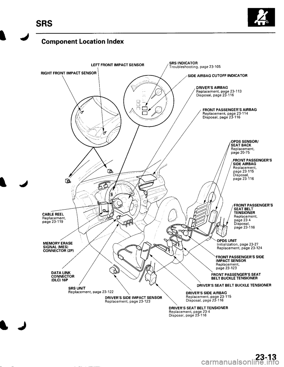
Component Location Index
LEFT FRONT IMPACT SENSOB
RIGHT FRONT IMPACT SENSOR
CABLE REELBeplacement,page 23-119
SIDE AIRBAG CUTOFF INDICATOR
DRIVER'S AIRBAGReplacement, page 23-1 13Disposal, page 23 1'16
SRS INOICATORTroubleshooting, page 23-105
FRONT PASSENGER'S AIRBAGReplacement, page 23-1 14Disposal, page 23'116
SENSOR/SEAT BACKReplacement,page 20-75
FRONT PASSENGER'SSIDE AIRBAGReplacement,page 23'1'15Disposal,page 23'116
FRONT PASSENGER'SSEAT BELTTENSIONERBeplacement,page 23-4Disposal,page 23-'116
MEMORY ERASESIGNAL (MES}CONNECTOR I2PI
DATA LINKCONNECTOR(DLCI 16P
OPDS UNITInitialization, page 23-27Replacement, page 23-124
PASSENGER'S SIOEIMPACT SENSORReplacement,page 23-123
FRONT PASSENGER'S SEATBELT BUCKLE TENSIONER
DRIVER'S SEAT BELT TENSIONERReplacement, page 23 4Disposal, page 23-116
23-13
Page 1034 of 1139
I
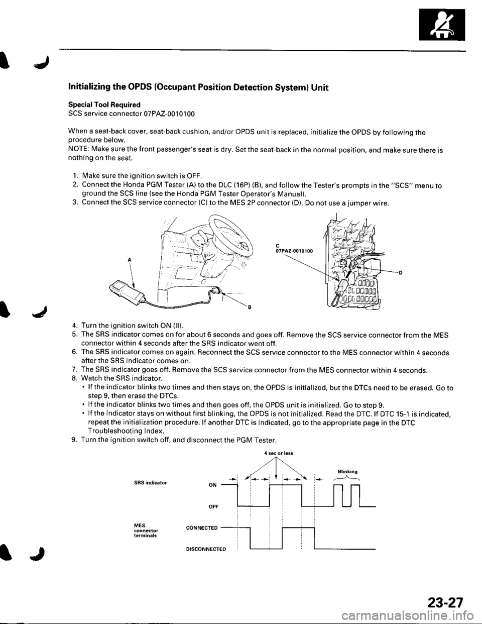
Initializing the OPDS {Occupant Position Detection System} Unit
Special Tool Required
SCS service connector 07PAz-00'1 01 00
When a seat-back cover, seat-back cushion, and/or OPDS unit is replaced, initialize the OPDS by following theprocedure below.
NOTE: Make sure the front passenger's seat is dry. Set the seat-back in the normal position, and make sure there isnothing on the seat.
'1. l\4ake sure the ignition switch is OFF.
2. Connect the Honda PGM Tester (A) to the DLC (16P) (B), andfollowtheTester's prompts jn the ,,SCS,, menu toground the SCS line (see the Honda PGM Tester Operator's ManuaD.
3. Connect the SCS service connector (C) to the MES 2P connector (D). Do not use a iumoer wire.
c07PAZ-00r0100
4. Turn the ignition switch ON {ll).
5. The SRS indicator comes on for about 6 seconds and goes off. Remove the SCS service connector from the MESconnector within 4 seconds after the SRS indicator went off.
6. The SRS indicator comes on again. Reconnect the SCS service connector to the MES connector within 4 secondsafter the SRS indicator comes on.
7. The SRS indicator goes off. Remove the SCS service connector from the MES connector withln 4 seconds.8. Watch the sRS indicator.'lftheindicatorblinkstwotimesandthenstayson,theOPDSisinitialized.buttheDTCSneedtobeerased.Goto
step 9, then erase the DTCS..lftheindicatorblinkstwotimesandthengoesoff,theOPDSunitisinitialized.Gotostep9.
' lf the indicator stays on without first blinking.the OPDS is not initialized. Readthe DTC. lf DTC 15-'l is indicated,repeat the initialization procedure. lf another DTC is indicated, go to the appropriate page in the DTCTroubleshooting Index.
9. Turn the ignition switch off, and disconnect the PGM Tester.
SBS indic.ror
MES
IJ
DISCONNECTED
23-27
Page 1035 of 1139
sRs
DTCDetection ltemNotes
t- |ODen in driver's airbaq inflator(see Daqe 23-36)
Increased resistance in driver's airbaq inflator(see Daoe 23-36
t-5Shon to another wire or decreased resistance in driver's airbag
inflator
(see page 23-37)
1-4Shortto Dower in driver's airbao inflator(see paqe 23-39
t-5Shortto qround in driver's airbaq inflator{see paqe 23-40
2-1Open in front Dassenqer's airbaq inflator{see oaoe 23-42
2-2Increased resistance in front passenqer's airbaq intlator(see oaqe 23-42
2-3Short to another wire or decreased resistance in front passenger's
airbao inflator
(see page 23-43)
2-4Short to oower in front oassenoer's airbaq inflator(see paqe 23-45
2-5Short to qround in front passenqer's airbaq inflator(see paqe 23-46
3-1ODen in driver's seat belt tensioner(see page 23-48
3-2lncreased resistance in driver's seat belt tensioner(see paqe 23-48
3-3Short to another wire or decreased resistance in driver's seat belt
tensioner
(see page 23-49)
3-4Short to oower in driver's seat belt tensioner(see Daqe 23-51
3-5Short to oround in driver's seat belt tensioner(see oaoe 23-52
21-1ODen or increased resistance in driver's seat belt buckle tensioner(see paqe 23-54
Short to another wire or decreased resistance in driver's seat belt
buckle tensioner
(see page 23-55)
2't -4Short to Dower in driver's seat belt buckle tensioner(see paqe 23-56)
2't-5Shon to oround in driver's seat belt buckle tensioner(see oaqe 23'57
4-'lODen in front oassenoer's seat belt tensioner{see page 23-58)
4-2lncreased resistance in front oassenqer's seat belttensioner{see paqe 23-58)
4-3Short to another wire or decreased resistance in front passenger's
seat belt tensioner
{see page 23-60)
4-4Shon to Dower in front Dassenqer's seat belt tensionerlsee oaqe 23-61
4-5Short to qround in front oassenoer's seat belt tensioner(see Daqe 23-63
Open or increased resislance in front passenger's seat belt buckle
tens ioner
(see page 23-64)
22-3Short to another wire or decreased resistance in front passenger's
seat belt buckle tensioner
(see page 23-65)
22-4Short to oower in front oassenqer's seat belt buckle tensioner(see paqe 23-66
22-5Short to oround in front oassenoer's seat belt buckle tensioner(see paqe 23-68
5-1lnternal failure of SRS unit
NOTE:
Before troubleshooting DTCS 5-1 through 8-6, check battery/system
voltage. lf the voltage is low, repair the cha rging system before
troubleshootino the SRS.
(see page 23-69)
5-2
5-4
5-8
6-3
6-4
6-7
6-8
1-)
7-3
8-1
a-2
8-4
8-5
8-6
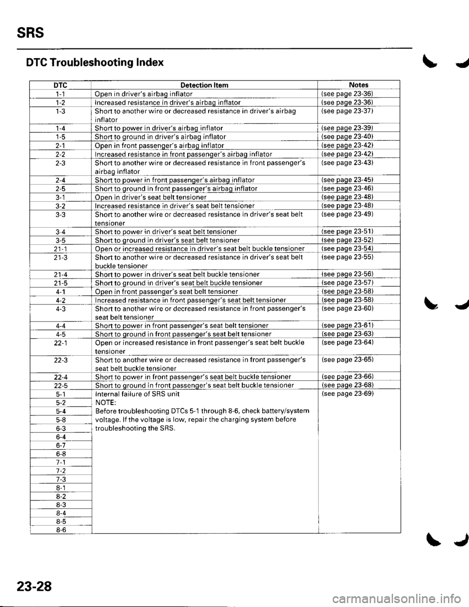
DTC Troubleshooting Indext.
tJ
23-28
\J
Page 1037 of 1139
SRS
SymptomDiagnostic procedureAlso check for
SRS indicator doesn't come onSRS Indicator Troubleshooting (see
paoe 23-105)
SRS indicator stays on when in"SCS" menu method
SRS Indicator Troubleshooting (see
step 1 on page 23-107)
Inability to retrieve DTCs with the
PGM Tester. Retrieve the flash
codes using the SCS menu method
(see page 23-24).
Slde airbag cutoff indicator stays
on after bulb check (lfthe
indicator stays on, it does not set
a DTC). Side airbag cutoff
indicator is flashing
. Make sure nothing is on the fronl
passenger's seat.. lf the side airbag cutoff indicator
stays on after the ignition switch
is turned ON (ll), initialize the
OPDS unit (see page 23-271.- lf the side airbag cutoff
indicator operates normallY, the
system is OK.- lf the side airbag cutoff
indicator stays on, replace the
uFU5 SenSOr {See SeCrOn ZUl.
The sensor is part of the seat-
back Dad.
DTC 15-2 troubleshooting
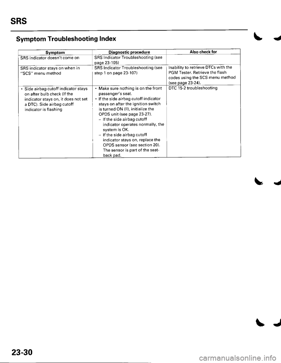
Symptom Troubleshooting Index\4
trJ
23-30
\J
Page 1119 of 1139
sRs
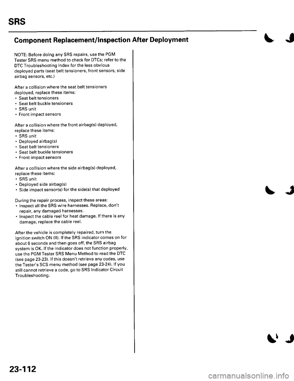
Component Replacement/lnspection After Deployment
NOTE: Before doing any SRS repairs. use the PGM
Tester SRS menu method to check for DTCS; refer to the
DTC Troubleshooting Index for the less obvious
deployed parts (seat beit tensioners, front sensors, side
airbag sensors, etc.)
After a collision where the seat belt tensioners
deployed, replace these items:' Seat belt tensioners. Seat belt buckle tensioners. SRS unit. Front impact sensors
After a collision where the front airbag(s) deployed.
replace these items:. SRS unit. Deployed airbag(s). Seat belt tensioners. Seat belt buckle tensioners. Front impact sensors
After a collision where the side airbag{s) deployed,
replace these items:. SRS unit. Deployed side airbag(s). Side impact senso(s)for the side(s) that deployed
During the repair process, inspect these areas:
. lnspect allthe SRS wire harnesses. Replace, don't
repair, any damaged harnesses.. Inspectthecable reelfor heatdamage. lf there is any
damage, replace the cable reel.
Afterthe vehicle is completely repaired, turn the
ignition switch ON (ll). lf the SRS indicator comes on for
about 6 seconds and then goes off, the SRS airbag
system is OK. lf the indicator does not function properly,
use the PGM Tester SRS Menu Method to read the DTC
(see page 23-23). lf this doesn't retrieve any codes, use
the Tester's SCS menu method (see page 23-24). lf you
still cannot retrieve a code, go to SRS Indicator Circuit
Troubleshooting.
23-112
\|J
Page 1133 of 1139
Service Manual lndex
)s
NOTE: Referto the lollowing listto look up A/C Pressure Switch CircuitDTCS, symptoms, fuses, connectors, wire Troubleshooting ......... ...-.-....-...-.-.-....-..21-32 Bharnesses, specifications, maintenanceschedules, and general serviceinlormation:
DTC Troubleshooting Indexes
A/C Signal CircuitTroubleshooting.........................-...... 11-'133 Back-up Light SwitchTest .......................................................... 13'3A/F lAir Fuel Ratiol SensorABS/TCS Components ........................ 19-34 Replacement ....................................... 1 1-113 Back-up Li9ht3EPS Components ................................. '17-22 Circuit DiagramFueland Emissions11-i A-Dillar Corner Trim
ABS Indicator Circuit
Heating/Ventilation ................................ 21-9 Replacement ...............-.....-..............-.... 20,96 Ball Joint BootssRS ........................................................ 23-28Replacement ......
... 19-52 Ball Joints
22-75
18 16
Remova1.............-.......... . ...........18-10Symptom Troubleshooting Indexes TroubleshootingABS/TCSComponents........................ 19 35Cruise Control System ..........................4 38 ABS Modulator-contml UnitEPS Components ................................. 17-23 Bemoval/lnstallation ............................ 19-57 BettervFan Controls10,12
Accessory Powor Socket Front
Blowor Pow€r Transistor
.......22 50
Blower UnitRemoval/lnstallation ............................ 21-39
Fuel and Em issions .............................. 11-10 ABS/TCS ComoonentsHeating/Ventilation..............................21 10 Component Location Index ................. 19-30 Beverage Holder
SRS ........................................................ 23'30 CircuitDiaqram.......................... 19'42Blower MotorReplacement .....21 41
21-38
Power 0istribution ...............................22-46 TesVReplacement .............................. 22'149Under-dash Fuse/Relay Box ............... 22 45Under-hood Fuse/Belay Box ...............22 44 Accessory Power Sockets
Fuse/Relay lndexes
(to harness)
Connector and Wire Harness lndexesComponent Connectors
Circuit Oiagram .................................. 22-149
Air Cleaner......2214 Rep1acemen1.....................................11-162
Air MixControl MotorMeintenence section .................... Section 3 Replacement ......................................... 21'34 Brake CelipersTest......................21-34 Overhaul19-14,23Gene.al lnlormation section........ Section 1
21.57
Airbag. Driver's
Ahernator FR Signal CircuitTroubleshooting .... .........-..........11 134
AntennaReplacement
Inspection ............................................. 19-24Rep|acement................. .................... 19-25
Bieke Meder Cylinder
Irake Discs
A
Replacement ....................................... 23 1 'l3 Inspection .................... ................... 19-13,22Repair ...........-...................................... 23 1 16Brake Fluid Level SwitchAirbag. Front Passenger's TestBeplacement....................................... 23-1 14AIC Brake LightsComponent Location fndex ...................21-3 Altemator CircuitDiagram....................................22-74Description.....................................-....21'1'l Beplacement ................ ........................... 4 29CircuitDiagram....................................21-14 Overhaul .................................................4-30 Brake Lines and Hoses
19.10
A/C CompressolReplacement .......-...-............................. 21 -41
A/C Compr€ssor ClulchRep1acement......................................... 19-15.........22-103 Inspection ............................................. 19-16Inspecton........Overhaul ..........
A/C CondenserReplacement,.,
21-442l-49 Audio Unit
Replacement
Brake PadsRemoval/lnstallation .. ........................22-100 Inspection/Rep1acement................ 19-11,20A/C Compressor Clutch CircuitTroubleshooting ................................... 21-30 Audio Unit Connector Brake Pedal22101 Adjustment..............19,6ArfC Comoressor Relief ValvcReplacement ..........-...-.......................... 21-51 Audio/Entertainment
A/C Compr$sor Thermal Protector Circuit DiagramReplacement............-............................ 21-51
Component Location In dex .................22-9A Test .......-.............. 22-84Breke Pedal Posilion Switch
Brake Pedal Position Switch Signal Clrcuit11-137
.....21 52
A/C Condenser Fan CircuitTroubleshooting ................... . . . . . .....21-28
)s
Troubleshooting
(cont'd)
Page 1134 of 1139
Service Manual Index
(cont'dl
Brake System Indicator CircuitCircuit DiagramConventional Brake Components..... 19-9TroubleshootingABS/TCS Components .... ....... ...... 19-55
Bulb, GeugeRep|acemenl................ .. ............2263
Bulb, HeadlightReplacement ......................................... 22-A1
Bumper, FrontRemoval/1nsra11ation ............................ 20 85
Bumper, RearRemoval/lnstallation... ... . .....20.86
Combination Light SwilchTesVReplacement ..............................22 80
Connecting Rod BearingsRep|acement...................... .......-....7-8
Connecting Rod Boltsf nspection ....................-.-.-.-.................... 7 -24
Connecting RodsInspection ........,,.,.,...,.,.,.,.,,,,.,,,.,.,.,.,.,.,.,.. 7 5
Connectors(See first page of this Index)
Conventional Brake Component3Component Location Index ................... 19'3Troub1eshootin9 ..................................... 19-4
Cylinder Head AssemblyComponent Location Index ..................... 6-3Inspection ................................................. 6 6Removal ..........&�23Insta11alion .............................................. 6 39
Cylinder Head Cover8emova1 ..............-.-................................. 6-22Installation ..............................................6-41
Cylinder Head, BareInspecton..,.....,.
D
c
Cable ReelReplacement....................................... 23-1 19
CamshaftInspection .......................-...-................... 6-29
Cargo Area LightTesVRep1acement ................................ 22-97
CarpetReplacement.....-...-..... ... ......-.20-55
Ceiling Light-estrReplacement ................................ 22.96
Charging SystemComponent Location Index................... 4-20Circuit Diagram ...................................... 4-21
19-8
CoolantInspection .................. ..... .. 106Replacement................. ... . .. 10 6
Coolant Temperature Gat|geTroub1eshootin9................................... 22 64
Cooling SyslemComponent Location Index................... 10-2
Countershaft BearingsReplacement............... ..................... 13-42
Cowl CoverReplacement............... .. ..... ....20-95
CrankshaftRemoval .................................................. 7 -12
Repair ..................
Inspec(on,,,,,........1 14
Dampers. FrontReplacement................ ..................... 18 20
Oampers, RearRep1acement......................................... 18-34
Dash VentsBemoval/lnstallation .-.......................... 20-64
DashboardBemoval/1nsta11ation ............................ 20-66
Oashboard Center PanelRemoval/1nstaf 1ation ............................ 20 62
Dashboard Lower CoverRemoval/lnstallation ...................... 20-59, 63
Dashboard Under CoverRemoval/lnstallation ............................ 20 60
Diff erential Carrier Bearings, M/TRep1acement,,......,...,...,.,.,,,.,.,,,........,.,. 13-54
Ditferential Oil Seals, M/T8ep1acement......................................... 13-55
Differential Pinion Gears, M/TInspection .,....-,.,,,.,..,.-,.,.........,.,.,,, 13 53
OLC CircuitTroubleshooting ................................ 1 1-109
Door GlassRep1acement.,.,,,,,,,,,,,.,,,,,,,,,,.,.,.,.,.,,,,,,.,, 20-9Adjustment. .. .....................20-11
Door Glass WeathelstripsReplacement .............-.. . . . ..........-......20 10
Door LatchesReplacement ..........-.-.............................. 20-7
Door Lock ActuatorsTest ...................................................... 22-154
Door Lock Knob SwitchesTest -......... . . . - . . . . . . . . ......22-160
Door Lock SwitchesTest ........... ............................ ............. 22-160
Door Outer HandlesRep1acemen1 ........................................... 20-6
3
Child Seat Tether AnchorRemoval/lnstaf lat;on .. ........................ 23 11
CKP (Crankshaft Position) SonsorReplacement....................................... 1 1-116
ClutchComponentLocation 1ndex................... 12-3Rep1acemen1........................................... 12-9
Clutch InteYlock SwitchTest.....-........-...-............. ...---.-.......4-6
Clutch Master CylinderReplacement........................................... 12 5
clutch PedalAdjustment ............................................. 12 4
Clutch Pedal Position SwitchTest.,.,,,,,.,,,.,.,,,,,,.,.,,,,,,,,,.,,,,,.. ......445
lnstallation.................. . ..... .....1-24
Crankshalt Main BearingsReplacement........-.-.................................. 7-6
CrankshaftOil Seal,Transmission End1nstanation .............................................. 7 28
Crankshafl PulleyRemoval/lnstallation -..................-.......... 6-1 1
Cruise Control Actuator
Troubleshooting
Clutch Slave CylindorBeplacemeit...
...................... 4-43
.......4-22
Test
12-1
RepIacement........................................... 4-44
Cruise Control Actuator CableAdjustment ............................................. 4 45
Cruise Control Main SwitchTesVRep1acement .................................. 4 42
Cruise Control Set/Resume/Cancel SwitchTesVRep1acement .................................. 4 42
Cruise Control SystomComponent Localion Inde\................... 4-36Circuit Diagram ....-................................. 4 37
Cruise Control UnitInputTest.............................. .. ...4,40CMP {Camshaft Positionl Senso]Replacement....-...-.............................. 1 1-128
CMP (TDC) SensorsReplacement............-.......................... 1 1 1 14
Page 1135 of 1139
)
Orive BehInspecaron................ 4-26
Door PanelsRemoval/lnstallation -............................. 20-4
Door Sash TrimRep1acement......................................... 20 10
Door StrikersAdiustment ........................................... 20-13
Door Weatherst psBeplacement...........-............................. 20 1 1
EPS Conirol UnitRemoval/1nsta11ation ..................-......... 17-67
EPS Indicator CircuitTroubleshooting ................................... 17 -47
EPS MotorRemoval/lnstallation .-.......................... 17-49
EVAP CanisterRep1acement......................... ......... 11,189
EVAP Control Syst€mComponentLocation Index ..............'11-170
EVAP Two-Wey ValveTest ..........-.............-............................ 11 186
Evaporetor CoreRep1acement........................ . ... 21-42
Evaporator Tomperature SensorReplacement......................................... 21 -37Test..................................... ..........2137
EvaporrtoFHeater UnitReplacement........................................ 21 43
Exhaust ManifoldRemoval/1nsta11ation ................................ I 7
Exhaust Pipe8ep|acement............................................. 9-8
Front SpeakersRep|acement....................................... 22-102
Front SuspensionComponentLocation Index................... 18-3
Fueland EmissionsDescription ........................................... 11-12
Fuel Fill DoorAdjustment ..........-................................ 20 93
Fuel Fill Door OpenetBeplacement........................ . ............ 20.109
Fuel Fill Door Opener CableReplacement....................................... 20- lO7
Fuel FilterReplacement....................................... 1 1-152
Fuel Gauge Sending UnitTest ......................-.-..........-.................. 11'156
Fuel Injection Syslem (PGM"FIlComponent Location 1ndex................. 11-49
Fuel IniectorsRep1acemen1....................................... 1 1 1 1 l
Fuel Lines and HosesInspection .......................................... 1 1'146Removal ....................... . .. . .... 11-149Insta|1ation .......................................... 1 1 150
FuelPipe ProtectolReplacement....................................... 20-104
Fuel Pressure RegulatotReplacement....................................... 1 1-152
Fuel Pulsation DamperReplacemenl................................... 11 154
Fuel PumpReplacement,,,,,.,.,.,,,.,,,,,,,,,,,,.,.,.,,,..,.. 11-153
Fuel Pump CircuitTroubleshooting -.......-....................... 1 1-141
FuelSupply SystemComponent Location lndex .............. 11 140Adjustment................................... 11-144Test........-...-................. ... ............- 11-145
FuelTankBeplacemenl.............. . ..... .. 11 155
Fuel Tank Vapor ControlValveTest ......................-....... ... . . 11-187Replacement,,.,,...,.,,,.,.,,,,... .. .. 11 189
Fuses{See first page ofthis Index)
)
Rep|acement................. ..................... 4 26
Drive Belt Auto-tensionellnspection ............................................... 4 21Rep1acement.................................... ..4-28
Driver's PocketRemoval/lnstallation -........................... 20-60
Driver's TrayRemoval/lnstallation .........................-.- 20-65
DRL {Daytime Running LightslControl Unitlnput Test .................... ........ . . . ......22-16
DTCs(See first page olthis Index)
Dust and Pollen FillerReplacement......................................... 21-39
Dynamic Damper, DriveshaftsReplacement........................................... 16-8
ECT SensorReplacement.,.,,,.,.,,,,,,,,,,,,,,................ 1 1-1 14
El€ctrical Power Steering IEPS)Signal CircuitTroubleshooting ........ ... .. 11-135
EmblemsReplacement......................-................ 20-100
Engine AssemblyRemova1 .................................................... 5 2Installation ............._.................................. 5-9
Engine Block AssemblyComponent Location Inder ..................... 7.3
Engine Block, BareInspect|onRepair
Fan ControlsComponent Location Index................. 10'l 1Circuit Diagram .. ..... . .. . .................. 10 13
Fender Fairing, FrontReplacement...-................................... 20-103
Final Driven Gear. M/TReplacement.... . . ................................ 13-53
FrameRepair Chan............ ... ....................... 20 11 4
Frame StiffenelReplacement......-................................ 20- J'13
Front ConsoleRemoval/lnstallation ............................ 20 5lDisassembJy/Reassemb|y ................... 20 58
Front DoorsComponent Location Index................... 20-2Adiustment ........................................... 20.12
Front Driveshaft AssemblyInspeclion .................... ... ....16 3Remova1...................-...... ... .....16-3Disassembly ............................... .....165Resassemb|y ................................-......... 16-9Insta11arion ........................ ...... ............ l6 17
Front lmpact SensorsRep1acement............................ ...23 125
................7-15................1 11
)
Entry Light Control SystemComponent Location Index ...............-. 22-89Circuit Dia9ram .................................... 22 90
EPS ComponentsComponent Location 1ndex..........-...... 17-!7Description ........................ ...... ..17-24Circuit Diagram11 26(cont'd)