Page 811 of 1139

Heating and Air Gonditioning
Blower Unit Removal and Installation {cont'd}
Remove the steering hanger beam bracket cover
from the right side of the glove box opening, then
remove the bolts and the olove box frame.
1.
8.
9.
Remove the ECM (see page 11-4).
Remove the EPS control unit (see page 17-67).
Disconnect and remove the PGM-Fl main relays
and bracket assembly, then remove the ECM
bracket.
Disconnect the connectors {A) from the blower
motor and the power transistor, then remove the
wire harness clips (B) and the connectors (C).
Remove the self-tapping screws and the bracket (D).
A
21-40
10. Disconnectthe connector {A) from the recirculation
control motor, then remove the wire harness clip
{B). Remove the mounting bolts, the mounting nuts
and the blower unit (C).
6x 1.0 mm I9.8 N.m (1.0 kgt.m,7.2 tbt.ftl
6x1.0mm9.8 N.m (1.0 kgf.m,?.2 tbf.ft)
11.
14.
Installlhe unit in the reverse order of removal.
Make sure that there is no air leakage.
Reconnect the negative battery terminal.
Do the engine control module (ECM) idle learn
procedure {see page 11-139).
Enter the anti-theft code for the radio, then enter
the customer's radio station presets.
\
'13.
Page 831 of 1139

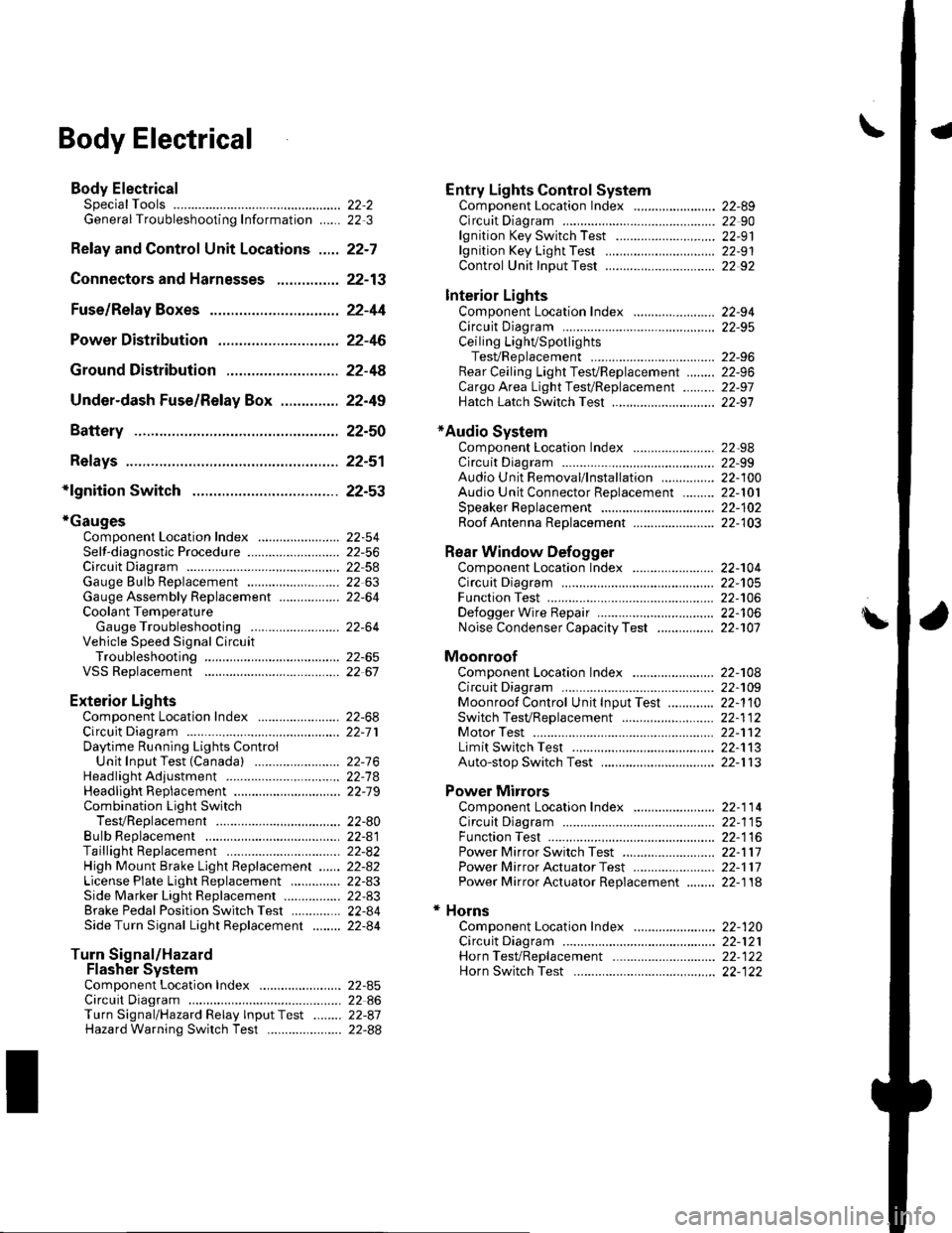
\Body Electrical
Body ElectricalSpecialToolsGeneral Troubleshooting tntorrnaiion.'......
Relay and Control Unit Locations .....
Connectors and Harnesses
Fuse/Relay Boxes ...............................
Power Distribution .............................
Ground Distribution ...........................
Under-dash Fuse/Relay Box ..............
Battery ..............
Relays ................
*lgnition Switch ..............
*Gauges
Component Location Index .......................Self-diagnostic Procedure ..........................Circuit DiagramGauge Bulb Replacement ..........................Gauge Assembly ReplacementCoolant Temperature
Gauge Troubleshooting .... ....................Vehicle Speed Signal CircuitTroubleshootingVSS Replacement
Exterior LightsComponent Location Index .......................Circuit DiagramDaytime Running Lights ControiUnit Input Test (Canada) ........................Headlight Ad,ustment .................. .. .....Headlighr Replacement ..............................Combination Light SwitchTest/ReplacementBulb ReplacementTaillight Replacement ..........................High Mount Brake Light Replacement ......License Plate Light Replacement ..............Side Marker Light Replacement ................Brake Pedal Position Switch Test ..............Side Turn Signal Light Replacement ........
Turn Signal/HazardFlasher SystemComponent Location Index .......................Circuit DiagramTurn Signal/Hazard Relay lnputTest ........Hazard Warning Switch Test
22,3
22-7
22-13
22-44
22-46
22-4A
22-49
22-50
22-51
22-53
22-5422-5622-5422 6322-64
22-64
22-6522 61
22-6822--71
22-7 622-7422-79
22-AO22-4122-8222-4222-4322-4322-4422-84
22-8�522 A622-8722-88
22-10422-105
22-10622-107
Entry Lights control systemComponent Location Index ....................... 22-89Circuit Diagram ......... 22 90lgnition Key Switch Test .....................,...... 22-9'llgnition Key Light Test ............................... 22-91Control Unit Input Test ..........,.................... 22 92
Interior LightsComponent Location Index ....................... 22-94Circuit Diagram ......... 22-95Ceiling LighVSpotlightsTesVReplacement ................................... 22-96Rear Ceiling Light TesVReplacem ent ........ 22-96Cargo Area Light Test/Replacem ent ......... 22-97Hatch Latch Switch Test ..,..,....................... 22-97
*Audio SystemComponent Location Index ....................... 22-98Circuit Diagram ......... 22,99Audio Unit Removal/lnstallation ............... 22-1OOAudio Unit Connector Replacement ......... 22-101Speaker Replacement ................................ 22-102Roof Antenna Rep1acement ....................-.. 22-103
Rear Window DefoggerComponent Location Index ...........Circuit Diasram .. ....... .. ..... ....... ...:::::.::.::.Function TestDefogger Wire Repair .................................Noise Condenser CapacityTest ................
MoonroofComponent Location Index ....................... 22-1OBCircuit Diagram ......... 22-109Moonroof Control Unit Input Test ............. 22-'l10Switch TesVReplacement ........,.....,........... 22-1 12Motor Test ................. 22-112Limit Swilch Test ...... 22-'l'13Auto-stop Switch Test ................................ 22-1 13
Power MirrorsComponent Location Index ....................... 22-114Circuit Diagram ......... 22-115Function Test ............. 22-116Power Mirror Switch Test .......................... 22-ll7Power Mirror Actuator Test ....................... 22-117Power Mirror Actuator Replacement ........ 22-11A
* HornsComponent Location Index ....................... 22-120Circuit Diagram ......... 22-121Horn TesVReplacement ...........................-. 22-122Horn Switch Test .,.... 22-122
\
Page 834 of 1139

General Troubleshooting Information
Tips and Precautions
Bef ore Troubleshooting
1. Check applicable fuses in the appropriate fuse/relay
oox.
2. Check the battery for damage. state of charge, and
clean and tight connections.
. Do not quick-charge a battery unless the battery
ground cable has been disconnected, otherwise
you will damage the alternator diodes.. Do not attempt to crank the engine with the
battery ground cable loosely connected or you
will severely damage the wiring.
Handling Connectors. Make sure the connectors are clean and have no
loose wire terminals.. Make sure multiple cavity connectors are packed with
dielectric grease (except waterti ght connectors).. All connectors have push-down release type locks (A).
Some connectors have a clip on their side used to
attach them to a mount bracket on the body or on
another component. This clip has a pull type lock.
Some mounted connectors cannot be disconnected
unless you first release the lock and remove the
connector from its mount bracket (A).
Never try to disconnect connectors by pulling on their
wires; pull on the connector halves instead.
Alwavs reinstall Dlastic covers,
Before connecting connectors, make sure the
terminals (A) are in place and not bent.
(cont'd)
22-3
Page 838 of 1139
Relay and Control Unit Locations
Engine Compartment
RADIATOR FANRELAY
BLOWER MOTOR RELAY
HORN RELAY
CONDENSER FANRELAY
UNDER-HOODFUSE/RELAY BOX
\...
,-:1-'...
ELD UNIT
22-7
Page 839 of 1139
Relay and Gontrol Unit Locations
Dashboard
_DAYTIME RUNNING LIGHTS EELAY lCanada)lWire colorsr RED, RED/YEL, ILRED/BLK and RED/8LU I_LOW BEAM CUT RELAY lcanada) _lWire colors: REDMHT, RED/BLK, ILBEDA/EL and RED/BLU I
KEYLESS RECEIVER UNIT
CRUISE CONTROL UNIT
'
'-.:- ':
..? ;,
POWER WINOOW RELAY
TURN SIGNAL/HAZARD RELAY
TAILLIGHT RELAYUNDER.DASHFUSE/RELAY BOX; .[:_- -
-l:r --
22-8
MULTIPLEX CONTROL UNIT
Page 841 of 1139
Relay and Control Unit Locations
a
\
Dashboard (cont'd)
L
SRS UNIT
EPS CONTROL UNITPGM.FI MAIN RELAY 1lWire colors: YEUBLK,LWHT/BLK, WHT/BLK and RED/YEL
PGM.FI MAN RELAY 2fwire colors: YEUBLK, ILYEUGRN, YEUBLK and GRN/YEL I
AIR/FUEL RATIO SENSOR RELAY[Wire colorsr WHT, WHT/RED, IOBN and BLK/ORN I
22-10
Page 842 of 1139
Rear and Roof
MOONROOF OPEN RELAY -Wire colors: GRNI/EL, GRN, ILRED/YEL, BLK and YEL/GRN IMOONROOF CLOSE RELAY
REAR WINDOW WIPER INTERMITTENTCONTBOL UNIT
fwire colors: GRN/BLK, GRN, lIGRN,AtVHT, BLK and YEL/GRN I
22-11
Page 843 of 1139
Relay and Control Unit Locations
Door and Seat
Driver's Door:
Passenger's Seat:
l\:
].\
POWER WINDOW MASTER SWITCHlHas built-in control unit)
22-12