2003 HONDA CIVIC %27
[x] Cancel search: %27Page 1106 of 1139
J
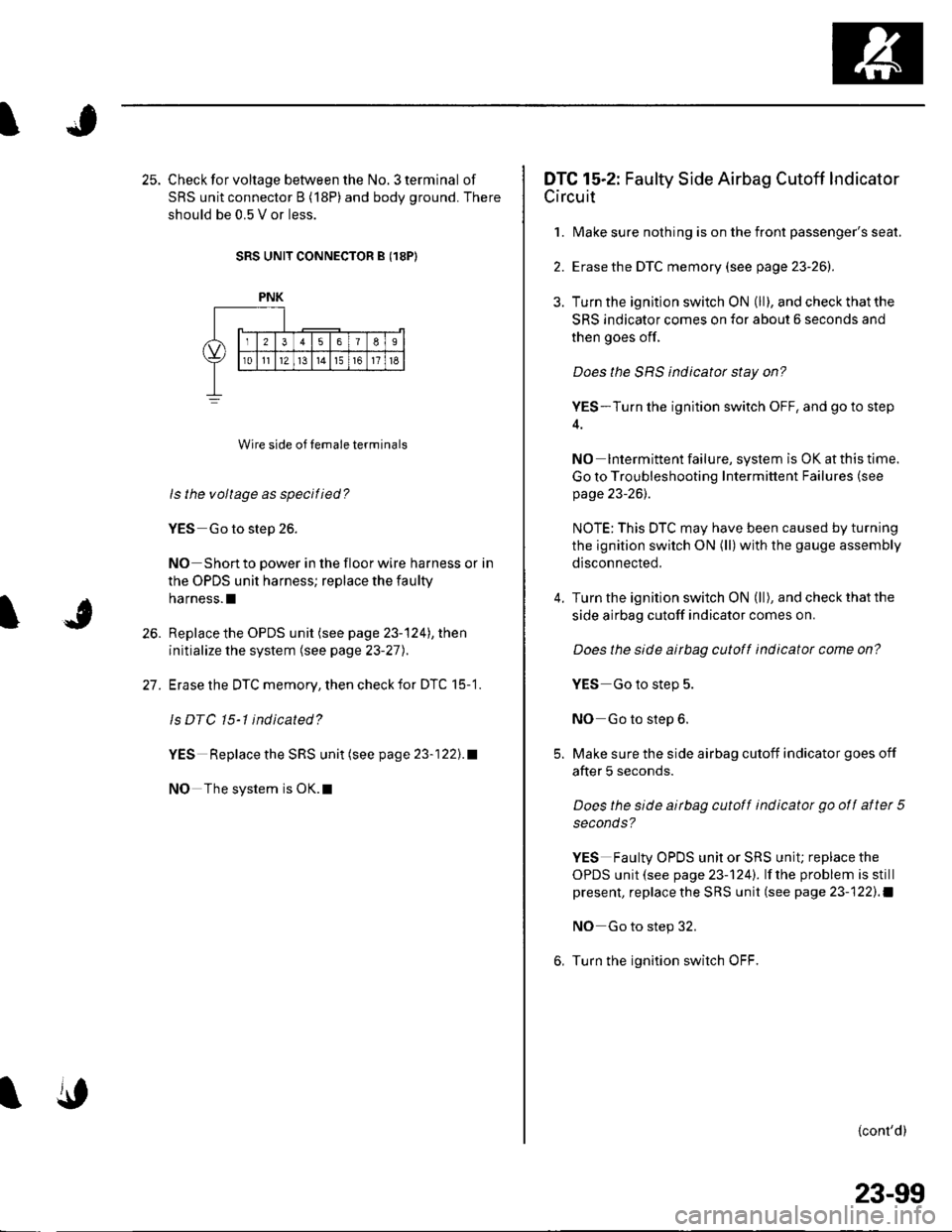
25. Check for voltage between the No. 3 terminal of
SRS unit connector B (18P) and body ground. There
should be 0.5 V or less.
SRS UNIT CONNECTOR B (18P)
Wire side of temale terminals
ls the voltage as specilied?
YES Go to step 26.
NO Short to power in the floor wire harness or in
the OPDS unit harness; replace the faulty
harness.l
Replace the OPDS unit (see page 23-'124), then
initialize the system (see page 23-27).
Erase the DTC memory, then check for DTC 15-1.
ls DTC 15-l indicated?
YES Replace the SRS unit (see page 23-122).1
NO The system is OK.l
26.
27.
PNK
DTC 15-2: Faulty Side Airbag Cutoff Indicator
Circuit
1. Make sure nothing is on the front passenger's seat.
2. Erase the DTC memory (see page 23-26]-.
3. Turn the ignition switch ON (ll),andcheckthatthe
SRS indicator comes on for about 6 seconds and
then goes off.
Does the SRS indicator stay on?
YES-Turn the ignition switch OFF, and go to step
NO Intermittent failure, system is OK at this time.
Go to Troubleshooting Intermittent Failures (see
page 23-26).
NOTE:This DTC may have been caused by turning
the ignition switch ON (ll)with the gauge assembly
disconnected.
Turn the ignition switch ON (ll), and checkthatthe
side airbag cutoff indicator comes on.
Does the side airbag cutoft indicator come on?
YES Go to step 5.
NO Go to step 6.
Make sure the side airbag cutoff indicator goes off
after 5 seconds.
Does the side airbag cutoff indicator go otf after 5
seconds?
YES Faulty OPDS unit or SRS uniu replace the
OPDS unit (see page 23-1241. lf the problem is still
present, replace the SRS unit (see page 23-122).)
NO Go to step 32.
Turn the ignition switch OFF.
{cont'd)
23-99
Page 1109 of 1139
sRs
23.
24.
DTC Troubleshooting (cont'dl
Turn the ignition switch OFF.
Remove the gauge assembly (see page 22-64l,.
With the connectors still connected to the gauge
assembly, backprobe the No. '15 terminal of gauge
assembly connector A (22P).
Turn the ignition switch ON {ll).
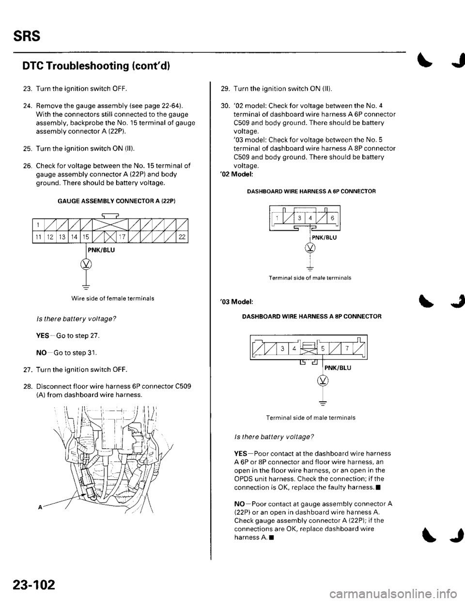
Check for voltage between the No. 15 terminal of
gauge assembly connector A {22P) and body
ground. There should be battery voltage.
GAUGE ASSEMBLY CONNECTOR A {22P)
Wire side of female terminals
ls thete battery voltage?
YES-Go to step 27.
NO Go to step 31.
Turn the ignition switch OFF.
Dlsconnect floor wire harness 6P connector C509
{A) from dashboard wire harness.
26.
27.
28.
23-102
\J
29. Turn the ignition switch ON (lli
30. '02 model: Checkforvoltage between the No.4
terminal of dashboard wire harness A 6P connector
C509 and body ground. There should be battery
vorlage.'03 model: Check for voltage between the No. 5
terminal of dashboard wire harness A 8P connector
C509 and body ground. There should be battery
vollage.'02 Model:
OASHBOARD WIRE HARNESS A 6P CONNECTOF
Terminal side of male terminals
'03 Model:
DASHBOARD WIRE HARNESS A 8P CONNECTOR
Terminal side of male terminals
ls there battety voltage?
YES Poor contact at the dashboard wire harness
A 6P or 8P connector and floor wire harness, an
open in the floor wire harness, or an open in the
OPDS unit harness. Check the connection; if the
connection is OK, replace the faulty harness.l
NO Poor contact at gauge assembly connector A
{22P) or an open in dashboard wire harness A.
Check gauge assembly connector A {22P); if the
connections are OK, replace dashboard wire
harness A.I
Page 1111 of 1139
sRs
DTG Troubleshooting (cont'dl
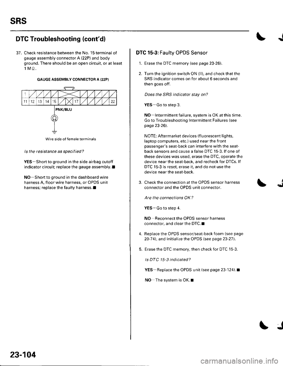
37. Check resistance between the No. 15 terminal of
gauge assembly connector A (22P) and body
ground. There should be an open circuit, or at least
1M0.
GAUGE ASSEMBLY CONNECTOR A I22PI
ls the resistance as specified?
YES-Short to ground in the side airbag cutoff
indicator circuit; replace the gauge assembly.l
NO Short to ground in the dashboard wire
harness A, floor wire harness, or OPDS unit
harness; replace the faulty harness.l
Wire side of female terminals
23-104
J
DTC 15-3: Faulty OPDS Sensor
1. Erase the DTC memory {see page 23-261.
2. Turn the ignition switch ON (ll), and check that the
SRS indicator comes on for about 6 seconds and
then goes off.
Does the SRS indicator stay on?
YES-Go to step 3.
NO Intermittent failure, system is OK at this time.
Go to Troubleshooting Intermittent Failures (see
page 23-26).
NOTE: Aftermarket devices (fluorescent lights,
laptop computers, etc.) used near the front
passenger's seat-back can interfere with the seat-
back sensors and cause a false DTC 15-3. lf one of
these devices was used, erase the DTC, operate the
device near the seat-back, and recheck for DTCs. lf
DTC 15-3 is reset, erase it, and do not use the
device near the seat-back.
3.
4.
Check the connection at the OPDS sensor harness
connector and the OPDS unit connector.
Are the connections OK?
YES-Go to step 4.
NO Reconnect the OPDS sensor harness
connector, and clear the DTC.I
Replace the OPDS sensor/seat-back foam (see page
20-141, and initialize the OPDS (see page 23-27).
Erase the DTC memory, then check for DTC 15-3.
ls DTC 15-3 indicated?
YES Replace the OPDS unit (see page 23-1241.a
NO The system is OK.l
{
Page 1115 of 1139
sRs
from the under-dash fuse/relav bor.
11.
18.
SRS Indicator Circuit Troubleshooting (cont'd)
'16. Disconnect dashboard wire harness B connector S
Turn the ignition switch ON {ll), and wait for 30
seconds. Then turn the ignition switch OFF,
Check the No. 13 (10A) fuse.
ls the f use OK?
YES Short to ground in dashboard wire harness
B; replace dashboard wire harness B.I
NO-Short to ground in the under-dash fuse/relay
box; replace the under-dash fuse/relay box.l
Turn the ignition switch OFF. Disconnect the
battery negative cable, and wait for 3 minutes.
Disconnect the driver's airbag 4P connector (see
step 2 on page 23-2'l).
Disconnect the front passenger's airbag 4P
connector (see step 3 on page 23-21).
Disconnect both seat belt tensioner 2P connectors
(see step 5 on page 23-22).
Disconnect SRS unit connector A (18P) from the
SRS unit (see step 7 on page 23-22).
19.
20.
21.
22.
23-108
24.Beconnect the battery negative cable.
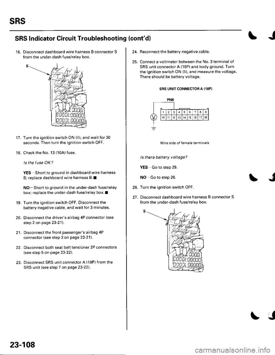
Connect a voltmeter between the No. 3 terminal of
SRS unit connector A (18P) and body ground. Turn
the ignition switch ON (ll), and measure the voltage.
There should be baftery voltage.
SRS UNIT CONNECTOR A (18PI
Wire side of female terminals
ls there battery voltage?
YES Go to step 29.
NO Go to step 26.
Turn the ignition switch OFF.
Disconnect dashboard wire harness B connector S
26.
27.
PNK
from the under-dash fuse/relav box.
Page 1129 of 1139
sRs
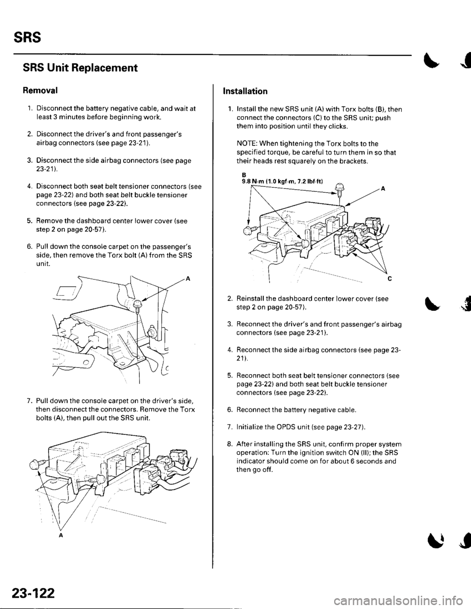
SRS Unit Replacement
Removal
'1. Disconnect the battery negative cable, and wait at
least 3 minutes before beginning work.
2. Disconnect the driver's and front passenger's
airbag connectors (see page 23-21).
3. Disconnectthe side airbag connectors (see page
23-211.
4.Disconnect both seat belt tensioner connectors (see
page 23-22) and both seat belt buckle tensioner
connectors {see page 23-221.
Remove the dashboard center lower cover (see
step 2 on page 20-57).
Pull down the console carpet on the passenger's
side, then remove the Torx bolt (A)from the SRS
unit.
7. Pull down the console carpet on the driver's side,
then disconnect the connectors. Remove the Torx
bolts (A), then pull out the SRS unit.
23-122
lnstallation
1, Installthe new SRS unit (A)with Torx bolts (B), then
connect the connectors {C) to the SRS uniu push
them into position until they clicks.
NOTE: When tightening the Torx bolts to the
specified torque, be careful to turn them in so that
their heads rest squarely on the brackets.
Reinstall the dashboard center lower cover (see
step 2 on page 20-57).
Reconnect the driver's and front passenger's airbag
connectors (see page 23-21]'.
Reconnect the side airbag connectors (see page 23-
211.
Reconnect both seat belt tensioner connectors (see
page 23-221 and both seat belt buckle tensioner
connectors (see page 23-22).
Reconnect the battery negative cable.
Initialize the OPDS unit (see page 23'27).
After installing the SRS unit, confirm proper system
operation: Turn the ignition switch ON (ll); the SRS
indicator should come on for about 6 seconds and
then go off.
4.
6.
8.
7.
9.8 N.m (1.0 kgf m, 7.2 lbf ft)
Page 1131 of 1139
sRs
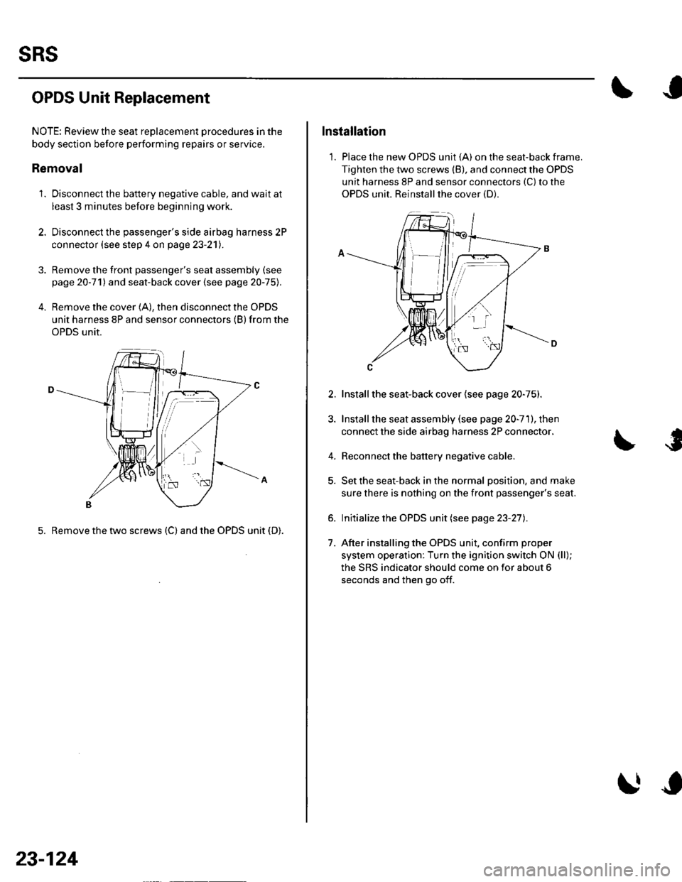
OPDS Unit Replacement
NOTE: Review the seat replacement procedures in the
body section before performing repairs or service.
Removal
1. Disconnect the battery negative cable. and wait at
least 3 minutes before beginning work.
2. Disconnect the passenger's side airbag harness 2P
connector (see step 4 on page 23-2'll.
3. Remove the front passenger's seat assembly (see
page 20-71)and seat-back cover (see page2O-15],.
4. Remove the cover (A), then disconnect the OPDS
unit harness 8P and sensor connectors (B) from the
OPDS unit.
5. Remove the two screws (C) and the OPDS unit (D).
23-124
Installation
1. Place the new OPDS unit (A) on the seat-back frame.
Tighten the two screws (B), and connect the OPDS
unit harness 8P and sensor connectors (C) to the
OPDS unit. Reinstallthe cover (D).
2.
4.
1.
Installthe seat-back cover (see page 20-75).
Install the seat assembly (see page 20-71), then
connect the side airbag harness 2P connector,
Reconnect the battery negative cable.
Set the seat-back in the normal position, and make
sure there is nothing on the front passenger's seat.
Initialize the OPDS unit (see page 23-27).
After installing the OPDS unit, confirm proper
system operation: Turn the ignition switch ON (ll);
the SRS indicator should come on for about 6
seconds and then go off.
Page 1136 of 1139
Service Manual Index
(cont'dl
Gauge A3semblyReplacement......................................... 22 64
Gaug€sComponent Location Index ..........-...... 22 54How-to lnformation ........................22-56Circuit Diagram22-54
Heater Valve CableAdjustment ...................... .................... ?1-46
High Mount Brake Light8ep|acement......................................... 22 82
Hood
lmmobilizer SystemComponent Location In dex .............. 22-162
\
G
Description
Genoral Information(See seclion 1)
Glove BoxRemoval/1nsta11ation .......................-.... 20-63
GrilleReplacement...........-............................. 20-94
Hood lnsulatorReplacement......................................... 20-89
Hood LatchRep1acement................... ..........20 108
Hood Opener CableComponentLocation Index ..............20 105Replacement ................ . . ........... .....20 106
Hood SealBeplacement.-...........................-........... 20-88
HornTesVReplacement . . ................ ...... 22-122
CircuitDiagram ...........................22-164Troubleshooting ............................ 22,165
Inner Fender, FronlRepf acemenl....................................... 20-102
Inside Rearview MirrorReplacement..........-.............................. 20 16
Instrument PanelRemoval/1nsta11ation................. ....... 20-59
Intake Air Bypass ControlThermal ValveTesr................................ ..... ..11-161
Intake Air SystemComponent Location Index ...-.-........ 11-159
Intake ManitoldRemoval/1nsta11ation ................................ I 2
lntermediate Shaft AssemblyRemova1 ................-.-...-......................... 16-19Disassemb|y................... ... ......-.... 16,20Resassemb|y ........................................ 16 22Installation .........-...-.............................. 16-24
Keyless Entry Transmitter
Adjuslment
H
Adiustment .......
Hatch Handle
Horn SwitchTest ............-........
HornsComponent Location IndexCirc!it Diagram
H02S. SecondaryReplacement
..............22-120Replacement
22-122
22 12120-110
20-'110Hatch LatchReplacement$
K
Hatch Latch Switch
.... 11 113
HubsReplacement. ... .................................. 1A 26Test
Test
Replacement
Hatch Support StrutsBeplacement.....
Hatch WeatherstrioReplacement....
Hazard Warning Switchtest
ldle ControlSystemComponentLocation Index .............. 11-129Inspection,.,.........-.......,.,.,,,,,,.,,,.,.,..... 1'l 138
lgnition CoillslBemoval/lnstallation ...............-.............. 4 18
22-161Test ...................................................... 22 161
Keyless Entry/Security Alarm SystemComponenl Location Index .............. 22 150Circuil Diagram ................. . .............. 22 151
Keyless Receiver Unitlnput Test ............................................ 22-153
Knock SensorReplacement......-................................ 1 1 115
KnucklesReplacementFront Suspensron ............................. 18-1 1Rear Suspension ........ .................-... 18-28
Repair ...............
H.tch Lock Actuator22-159
Hatch Lock CylinderRep|acement....................................... 20,111
Hatch SpoilerIAT {lntake Air Temperature} SensorReplacement.,.........-...'11 115
20-91
20-92
.................... 22_88lgnition Key LightTest,,.,,,,.,...,......-.
H6adlightAdjustmentlgnition Key Switch
....................... 22-91
....................... 22-91..22-78TestReQ\ace$entlgnition SwitchTest .,,,.,.,.,,,,.,.,.......22-53License Plate LightReplacement...........-... - ... .....22-83
License TrimReplacement..................-...-..........-....... 20-98
Lights, ExteriorComponent Localion Index.................22 68
Lights,InteriorComponent Location Index................. 22-94CircuitDiagram .. .. ...... .... 22-95
HcadlightsCircuit Diagram .............................. 22-71, 72
HeadlinerRemoval/lnstallalion ............................ 20-54
Heater ControlPanelRemoval/1nsta11ation ............................ 21-38
Heater Control Power and Ground CircuitsTroubfeshooting......... .......................21-27
lgnition SystemComponent Location Index ................... 4-15CircuitDia9ram .................................... 4'161nspection ............................................... 4-17
lmmobilizer Control Unit-Receiver
J
22-161
Page 1137 of 1139
)
Low Fuel lndicatorTest.....................11-158Moonroof Drain Channel SliderReplacement......................................... 20'44
Moonroof FrameRep1acement,,,,,,,,,,.,.,.,.,.,.,.,,,,,,............ 20 42
MoonroolGlassAdiustment ........................................... 20-37Rep1acement......................................... 20 37
Moonroot Limit SwitchAdjustment ........................................-.- 20 46Test ...................................................... 22 113
Moonrool MotorReplacement....-.................................... 2D-41
Oil Pressure SwitchTest ................-.-........-................................ 8-4Replacement.........-................................. 8-16
Oil Pump, EngineOverhau1 ................................................... 8-8
Oil, EngineReplacement...-................-.-...................... 8-5
OPDS UnitReplacement....................................... 23- 124
Outside Mirror HoldersBeplacement......................................... 20-15
Outside Power Mirror ActuatorsTest ...................................................... 22-117Bepf acement..-.................................... 22-1 14
Outside Power Mirror SwitchTest ..-................................................... 22-111
Outsid€ Power MirrorsReplacement............................ ... .. . . . 20-15Component Location lndex .............. 22- 114Circuit Diagram .................................. 22-115Test -..................................................... 22-116
Lower ArmsRemoval/1nsta11ation............................ 18 19
Lubrication SystemComponent Location Index..................... 8-3Test............................................................ 8 4
M
M/TAssemblyRemoval.......... 13-4 Test...................... 22-1 12lnstallation............. 13-8
.........21,35
Disassembly ......................................... 13-14Resassembly .. ... ................. 13-46
M/TChange Leverlnspection ............................................. 13-19Disassembly 8eassemb1y ................... 13-20
M/T Countershaft AssemblyInspection ....................................... 13 31, 33Disassemb1y ......................................... 13-32Resassemb|y ........................................ 13-34
M/T DifferentialComponentLocation Index................. 13-52Adiuslment ........................................... 13-56
M/T Maifthaft Assembly1nspection ... ................................... 13-23, 26Disassembly ......................................... 13 25Resassembly ........................................ 13 28Adjustment ........................................... 13-43
M/T Reverse Shift ForkInspection .................... ........................ l3 19
M/T Shift LevelReplacement......................................... 13-51
Mainshaft BearingsReplacement....,.................................... 13 41
MairtenancelSee section 3)
MILHow to Informatron ............................. 1 1.46
MIL CircuitTroubleshooting .......... .- . . . . ......... 11 97
MirrorsComponentLocation Index................. 20'14
Mode Control MotorReplacement
Moonrool SunshadeRep1acement....................... . . ............. 20 40
Moonroof SwitchTesVRep1acement .............................. 22- l 12
Mooniool Wind Def lectorReplacement.......................-................. 20-38
Moonroof/SunroofComponent Location Index ... 20-35, 22-108Test ........................................................ 20-48Cf rcuit Diagram .................................. 22- 109
MTFInspection/Rep1acement. .......... ........... 13-3
Muhiplex Control SystemComponentLocation lndex ..............22 168Circuit Diagram .................................. 22-1690escription ......................................... 22-17 1Troubleshooting ................................ 22-17 2
Muliiplex Control Unit, Under-dashInput TestEntry Light Control Sysiem ............. 22-92Keyless Entry/Security AlarmSystern .-....................................... 22-155MultiplexControl System .............22 115Wiper/Washer................................. 22'1 41
NoiseTest,,Reduction Condenser
Parking ErakeInspection Adjustment ........... .............. 19-7
Parking Brake CableRep1acement......................................... 19-26
Parking Erake Switch
P
l
Test ...................... 19-10
Test............................... . ...........2135
Moonroof Auto Stop SwitchosTest ...................................................... 22'113
Moon.oot Control Unillnput Test ............................................ 22-110
Moonroof Drein ChannelBeplacement ... . ....... ......................... 20 39
Oil Filte]Replacement............................................. 8-6
Oil Filter Feed PipeReplacement............... . ..-,...,.,,,,,,,,8-7
Oil PanRemoval .............,.,,,,,,,,,,,,.,.,,,.........-....... 7 1 1lnstallation .............................................. 7 -27
Passenger's TraVRemoval/lnstallation ............................ 20-65
PCV ValveBeplacement....................................... 1 1'169Test........................................... l1 169
Piston Rings8ep1acement................................-.-...-.- 7-21
PistonsReplacement...................-....................... 7-181nsta|1ation ...................................... ...1-23
Power R€layTest ...............-.-...................................... 22-51
Power Window Motor, Driver'stesl.....,,,, .,.,,,............
Power Window Motors, Passenger's
Power Window Switch, Masterlnput Test ..........-.........-....................... 22-126Tesr ....... . ............................................ 22 124Replacement....................................... 22-133
N
..............22 101
o
l' ,e
(cont'd)