Page 33 of 240
MANUAL HEATING AND AIR CONDITIONING SYSTEM WITH REAR
PASSENGER COMPARTMENT CLIMATE CONTROL SYSTEM
(IF EQUIPPED)
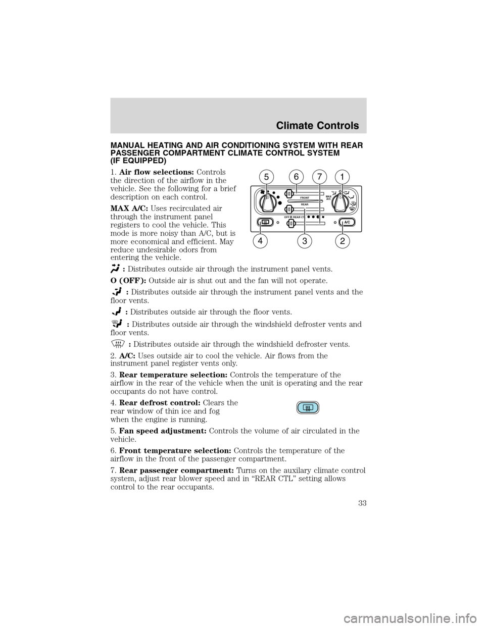
1.Air flow selections:Controls
the direction of the airflow in the
vehicle. See the following for a brief
description on each control.
MAX A/C:Uses recirculated air
through the instrument panel
registers to cool the vehicle. This
mode is more noisy than A/C, but is
more economical and efficient. May
reduce undesirable odors from
entering the vehicle.
:Distributes outside air through the instrument panel vents.
O (OFF):Outside air is shut out and the fan will not operate.
:Distributes outside air through the instrument panel vents and the
floor vents.
:Distributes outside air through the floor vents.
:Distributes outside air through the windshield defroster vents and
floor vents.
:Distributes outside air through the windshield defroster vents.
2.A/C:Uses outside air to cool the vehicle. Air flows from the
instrument panel register vents only.
3.Rear temperature selection:Controls the temperature of the
airflow in the rear of the vehicle when the unit is operating and the rear
occupants do not have control.
4.Rear defrost control:Clears the
rear window of thin ice and fog
when the engine is running.
5.Fan speed adjustment:Controls the volume of air circulated in the
vehicle.
6.Front temperature selection:Controls the temperature of the
airflow in the front of the passenger compartment.
7.Rear passenger compartment:Turns on the auxilary climate control
system, adjust rear blower speed and in“REAR CTL”setting allows
control to the rear occupants.
A/C
FRONT
REAR
OFFMAX
A/C
REAR CTL
234
1567
Climate Controls
33
Page 40 of 240
BULBS
Replacing exterior bulbs
Check the operation of all the bulbs frequently.
Using the right bulbs
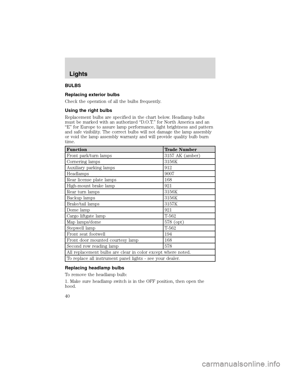
Replacement bulbs are specified in the chart below. Headlamp bulbs
must be marked with an authorized“D.O.T.”for North America and an
“E”for Europe to assure lamp performance, light brightness and pattern
and safe visibility. The correct bulbs will not damage the lamp assembly
or void the lamp assembly warranty and will provide quality bulb burn
time.
Function Trade Number
Front park/turn lamps 3157 AK (amber)
Cornering lamps 3156K
Auxiliary parking lamps 912
Headlamps 9007
Rear license plate lamps 168
High-mount brake lamp 921
Rear turn lamps 3156K
Backup lamps 3156K
Brake/tail lamps 3157K
Dome lamp 921
Cargo liftgate lamp T-562
Map lamps/dome 578 (opt)
Stepwell lamp T-562
Front seat footwell 194
Front door mounted courtesy lamp 168
Second row reading lamp 578
All replacement bulbs are clear in color except where noted.
To replace all instrument panel lights - see your dealer.
Replacing headlamp bulbs
To remove the headlamp bulb:
1. Make sure headlamp switch is in the OFF position, then open the
hood.
Lights
40
Page 43 of 240
Replacing license plate lamp bulbs
1. Make sure the headlamp is in the
OFF position and remove two
screws and the license plate lamp
assembly from the liftgate.
2. Remove bulb socket by pulling it
straight out of the lamp assembly.
3. Carefully pull the bulb out from
the socket.
Install the new bulb(s) in reverse order.
Replacing high-mount brakelamp bulbs
1. Open liftgate and gently pry the
access cover off the liftgate trim
panel.
2. Rotate the bulb socket
counterclockwise and remove.
3. Carefully pull bulb straight out.
Install the new bulb(s) in reverse order.
Replacing cornering lamp bulbs (if equipped)
For bulb replacement, see a dealer or qualified technician.
Replacing auxiliary parking lamp bulbs (if equipped)
For bulb replacement, see a dealer or qualified technician.
Lights
43
Page 50 of 240
AUXILIARY POWER POINT
Power outlets are designed for accessory plugs only. Do not hang
any type of accessory or accessory bracket from the plug.
Improper use of the power outlet can cause damage not covered
by your warranty.
Do not plug optional electrical accessories into the cigarette lighter. Use
the power point.
Do not use the power point for operating the cigarette lighter element.
The Maximum power each power point can supply depends on the fuse
rating. For example: a 20A fuse should supply a maximum of 240 Watts,
a 15A fuse should supply a maximum of 180 Watts and a 10A fuse should
supply a maximum of 120 Watts. Exceeding these limits will result in a
blown fuse.
Always keep the power point caps closed when not being used.
POWER WINDOWS
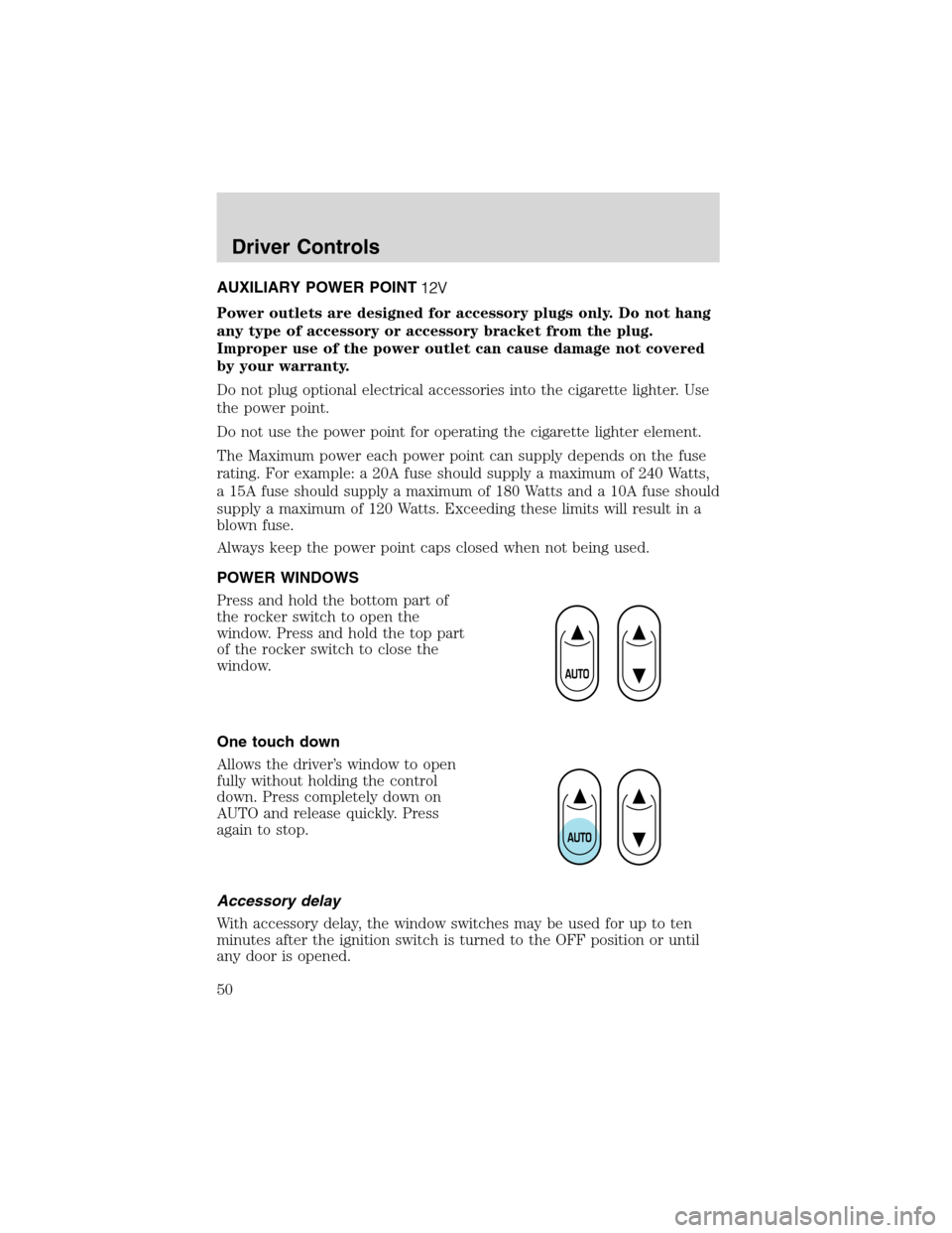
Press and hold the bottom part of
the rocker switch to open the
window. Press and hold the top part
of the rocker switch to close the
window.
One touch down
Allows the driver’s window to open
fully without holding the control
down. Press completely down on
AUTO and release quickly. Press
again to stop.
Accessory delay
With accessory delay, the window switches may be used for up to ten
minutes after the ignition switch is turned to the OFF position or until
any door is opened.
Driver Controls
50
Page 155 of 240
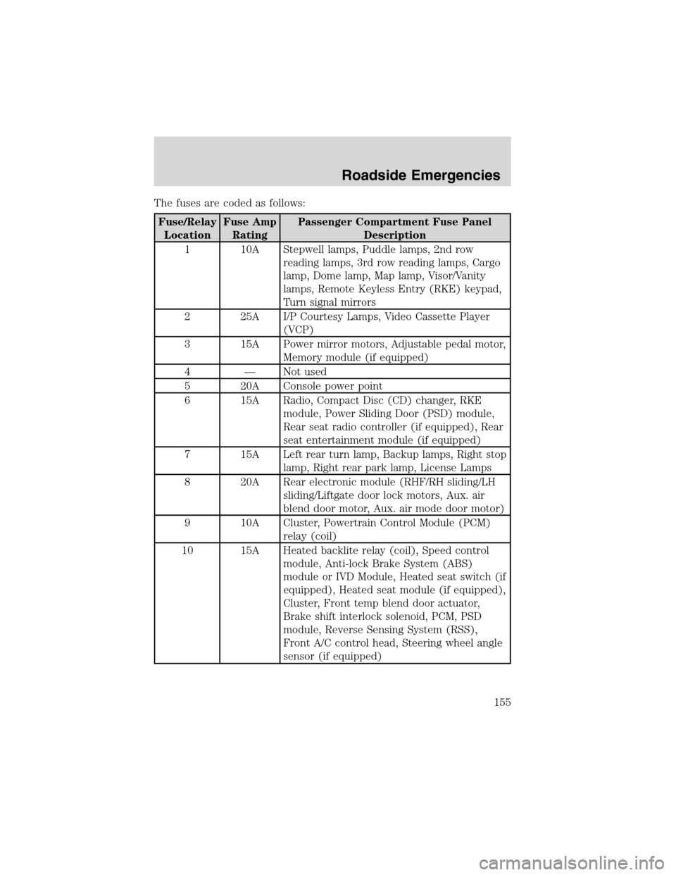
The fuses are coded as follows:
Fuse/Relay
LocationFuse Amp
RatingPassenger Compartment Fuse Panel
Description
1 10A Stepwell lamps, Puddle lamps, 2nd row
reading lamps, 3rd row reading lamps, Cargo
lamp, Dome lamp, Map lamp, Visor/Vanity
lamps, Remote Keyless Entry (RKE) keypad,
Turn signal mirrors
2 25A I/P Courtesy Lamps, Video Cassette Player
(VCP)
3 15A Power mirror motors, Adjustable pedal motor,
Memory module (if equipped)
4—Not used
5 20A Console power point
6 15A Radio, Compact Disc (CD) changer, RKE
module, Power Sliding Door (PSD) module,
Rear seat radio controller (if equipped), Rear
seat entertainment module (if equipped)
7 15A Left rear turn lamp, Backup lamps, Right stop
lamp, Right rear park lamp, License Lamps
8 20A Rear electronic module (RHF/RH sliding/LH
sliding/Liftgate door lock motors, Aux. air
blend door motor, Aux. air mode door motor)
9 10A Cluster, Powertrain Control Module (PCM)
relay (coil)
10 15A Heated backlite relay (coil), Speed control
module, Anti-lock Brake System (ABS)
module or IVD Module, Heated seat switch (if
equipped), Heated seat module (if equipped),
Cluster, Front temp blend door actuator,
Brake shift interlock solenoid, PCM, PSD
module, Reverse Sensing System (RSS),
Front A/C control head, Steering wheel angle
sensor (if equipped)
Roadside Emergencies
155
Page 156 of 240
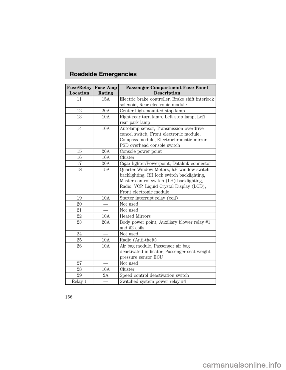
Fuse/Relay
LocationFuse Amp
RatingPassenger Compartment Fuse Panel
Description
11 15A Electric brake controller, Brake shift interlock
solenoid, Rear electronic module
12 20A Center high-mounted stop lamp
13 10A Right rear turn lamp, Left stop lamp, Left
rear park lamp
14 10A Autolamp sensor, Transmission overdrive
cancel switch, Front electronic module,
Compass module, Electrochromatic mirror,
PSD overhead console switch
15 20A Console power point
16 10A Cluster
17 20A Cigar lighter/Powerpoint, Datalink connector
18 15A Quarter Window Motors, RH window switch
backlighting, RH lock switch backlighting,
Master control switch (LH) backlighting,
Radio, VCP, Liquid Crystal Display (LCD),
Front electronic module
19 10A Starter interrupt relay (coil)
20—Not used
21—Not used
22 10A Heated Mirrors
23 20A Body power point, Auxiliary blower relay #1
and #2 coils
24—Not used
25 10A Radio (Anti-theft)
26 10A Air bag module, Passenger air bag
deactivated indicator, Passenger seat weight
pressure sensor ECU
27—Not used
28 10A Cluster
29 2A Speed control deactivation switch
Relay 1—Switched system power relay #4
Roadside Emergencies
156
Page 157 of 240
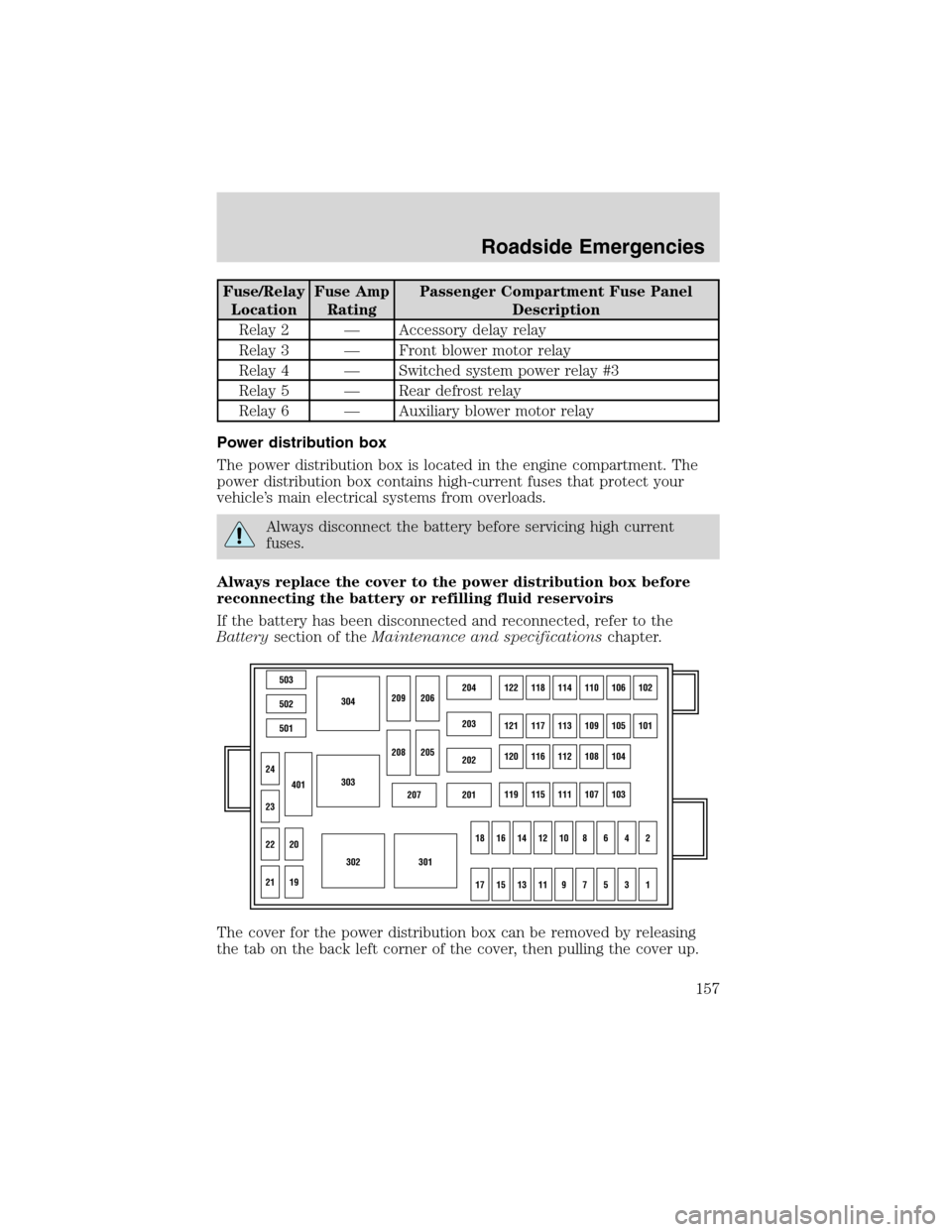
Fuse/Relay
LocationFuse Amp
RatingPassenger Compartment Fuse Panel
Description
Relay 2—Accessory delay relay
Relay 3—Front blower motor relay
Relay 4—Switched system power relay #3
Relay 5—Rear defrost relay
Relay 6—Auxiliary blower motor relay
Power distribution box
The power distribution box is located in the engine compartment. The
power distribution box contains high-current fuses that protect your
vehicle’s main electrical systems from overloads.
Always disconnect the battery before servicing high current
fuses.
Always replace the cover to the power distribution box before
reconnecting the battery or refilling fluid reservoirs
If the battery has been disconnected and reconnected, refer to the
Batterysection of theMaintenance and specificationschapter.
The cover for the power distribution box can be removed by releasing
the tab on the back left corner of the cover, then pulling the cover up.
503
304
303
302301
502
501
207201
202
203
204122118114110106102
121117113109105101
120116112108104
119115111107103
24
209206
208
18161412108642
1715131197531
205
23
22
21
401
20
19
Roadside Emergencies
157
Page 158 of 240
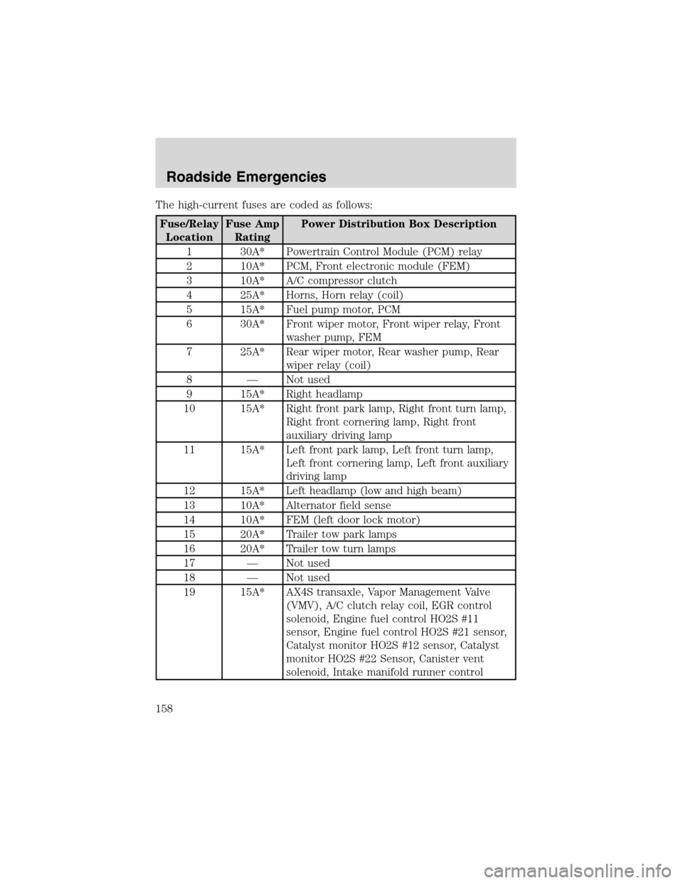
The high-current fuses are coded as follows:
Fuse/Relay
LocationFuse Amp
RatingPower Distribution Box Description
1 30A* Powertrain Control Module (PCM) relay
2 10A* PCM, Front electronic module (FEM)
3 10A* A/C compressor clutch
4 25A* Horns, Horn relay (coil)
5 15A* Fuel pump motor, PCM
6 30A* Front wiper motor, Front wiper relay, Front
washer pump, FEM
7 25A* Rear wiper motor, Rear washer pump, Rear
wiper relay (coil)
8—Not used
9 15A* Right headlamp
10 15A* Right front park lamp, Right front turn lamp,
Right front cornering lamp, Right front
auxiliary driving lamp
11 15A* Left front park lamp, Left front turn lamp,
Left front cornering lamp, Left front auxiliary
driving lamp
12 15A* Left headlamp (low and high beam)
13 10A* Alternator field sense
14 10A* FEM (left door lock motor)
15 20A* Trailer tow park lamps
16 20A* Trailer tow turn lamps
17—Not used
18—Not used
19 15A* AX4S transaxle, Vapor Management Valve
(VMV), A/C clutch relay coil, EGR control
solenoid, Engine fuel control HO2S #11
sensor, Engine fuel control HO2S #21 sensor,
Catalyst monitor HO2S #12 sensor, Catalyst
monitor HO2S #22 Sensor, Canister vent
solenoid, Intake manifold runner control
Roadside Emergencies
158