2003 FORD WINDSTAR reset
[x] Cancel search: resetPage 70 of 240
Compass display (if equipped)
The compass reading may be affected when you drive near large
buildings, bridges, power lines and powerful broadcast antennas.
Magnetic or metallic objects placed in, on or near the vehicle may also
affect compass accuracy.
Usually, when something affects the compass readings, the compass will
correct itself after a few days of operating your vehicle in normal
conditions. If the compass still appears to be inaccurate, a manual
calibration may be necessary. Refer toCompass zone/calibration
adjustment.
Most geographic areas (zones) have a magnetic north compass point that
varies slightly from the northerly direction on maps. This variation is four
degrees between adjacent zones and will become noticeable as the
vehicle crosses multiple zones. A correct zone setting will eliminate this
error. Refer toCompass zone/calibration adjustment.
Compass zone/calibration adjustment
Perform this adjustment in an open area free from steel structures and
high voltage lines.
For optimum calibration, turn off all electrical accessories (heater/air
conditioning, wipers, etc.) and make sure all vehicle doors are shut.
1. Turn ignition to the ON position.
2. Start the engine.
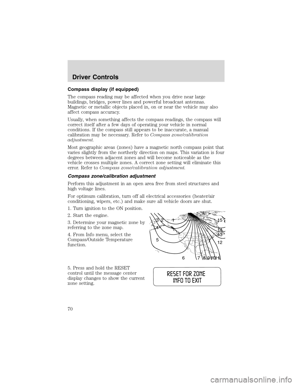
3. Determine your magnetic zone by
referring to the zone map.
4. From Info menu, select the
Compass/Outside Temperature
function.
5. Press and hold the RESET
control until the message center
display changes to show the current
zone setting.
1 2 3
4
5
6 7 8 9 101112 13 14 15
Driver Controls
70
Page 71 of 240
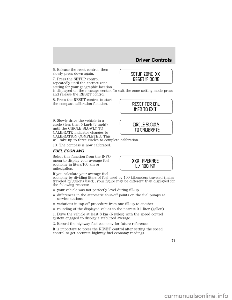
6. Release the reset control, then
slowly press down again.
7. Press the SETUP control
repeatedly until the correct zone
setting for your geographic location
is displayed on the message center. To exit the zone setting mode press
and release the RESET control.
8. Press the RESET control to start
the compass calibration function.
9. Slowly drive the vehicle in a
circle (less than 5 km/h [3 mph])
until the CIRCLE SLOWLY TO
CALIBRATE indicator changes to
CALIBRATION COMPLETED. This
will take up to three circles to complete calibration.
10. The compass is now calibrated.
FUEL ECON AVG
Select this function from the INFO
menu to display your average fuel
economy in liters/100 km or
miles/gallon.
If you calculate your average fuel
economy by dividing liters of fuel used by 100 kilometers traveled (miles
traveled by gallons used), your figure may be different than displayed for
the following reasons:
•your vehicle was not perfectly level during fill-up
•differences in the automatic shut-off points on the fuel pumps at
service stations
•variations in top-off procedure from one fill-up to another
•rounding of the displayed values to the nearest 0.1 liter (gallon)
1. Drive the vehicle at least 8 km (5 miles) with the speed control
system engaged to display a stabilized average.
2. Record the highway fuel economy for future reference.
It is important to press the RESET control after setting the speed
control to get accurate highway fuel economy readings.
Driver Controls
71
Page 72 of 240

DIST TO EMPTY (DTE)
Selecting this function from the
INFO menu will give you an
estimate of how far you can drive
with the fuel remaining in your tank
under normal driving conditions.
Remember to turn the ignition OFF when refueling your vehicle.
Otherwise, the display will not show the addition of fuel for a few
kilometers (miles).
The DTE function will display LOW FUEL LEVEL and sound a tone for 1
second when you have low fuel level indicated on the fuel gauge.
TRIP ELAPSED DRIVE TIME
Select this function from the INFO menu to display your trip elapsed
drive time and will display and accumulate when the key is in the RUN
position.
1. Press the INFO control until the message center display shows the
TRIP ELAPSED TIME XXXX.
2. Hold the RESET control down for two seconds to clear display.
DISPLAY ON/OFF
Select this function from the INFO menu to turn your message center
display OFF or ON.
LIFTGATE
To unlock the liftgate, insert door
key into the lock and turn
clockwise. You can also unlock the
latch (but not release it) with the
power door lock system and remote
entry key fob.
To open the liftgate, squeeze the
liftgate handle.
•Do not open the liftgate in a
garage or other enclosed area
with a low ceiling. If the liftgate is opened, the liftgate could be
damaged against a low ceiling.
•Do not leave the liftgate open while driving. Doing so could cause
serious damage to the liftgate and its components as well as allowing
carbon monoxide to enter the vehicle.
Driver Controls
72
Page 111 of 240
Failure to inspect and if necessary replace the safety belt
assembly under the above conditions could result in severe
personal injuries in the event of a collision.
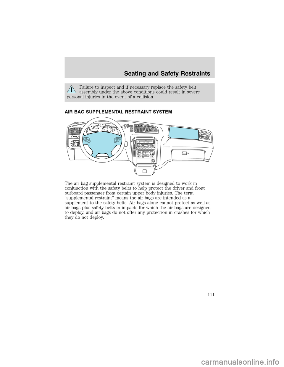
AIR BAG SUPPLEMENTAL RESTRAINT SYSTEM
The air bag supplemental restraint system is designed to work in
conjunction with the safety belts to help protect the driver and front
outboard passenger from certain upper body injuries. The term
“supplemental restraint”means the air bags are intended as a
supplement to the safety belts. Air bags alone cannot protect as well as
air bags plus safety belts in impacts for which the air bags are designed
to deploy, and air bags do not offer any protection in crashes for which
they do not deploy.
FM 1
AMC
BL RF ST
mi
AUTOP
12345
6
7RPMX1000 THEFT TRAC
ACTIVE TRAC
OFFFFUEL
E404080
120
1602060
80100 MPHTEMP
Hkm/hBRAKEO/D
OFFO/D
ON/OFFINFOSETUP
RESET
DISC
EJMUTEVOL - PUSH ONOFF
T/C
REW FFSCAN
BASS TREB SEL BALTAPE EJ CD
FADEAUTO
CLK
SIDE 1-2 COMP SHUFFLESEEK
TUNE AM FM12 3456DOLBY B NR
A/CFRONT
REAR
OFFMAX
A/C
REAR
CONT
ONSET+RESCST-OFF
Seating and Safety Restraints
111
Page 151 of 240
Canadian customers who require roadside assistance, call
1–800–665–2006.
If you need to arrange roadside assistance for yourself, Ford Motor
Company will reimburse a reasonable amount. To obtain reimbursement
information, U.S. Ford or Mercury vehicles customers call
1-800-241-3673; Lincoln vehicle customers call 1–800–521–4140.
Canadian customers who need to obtain reimbursement information, call
1–800–665–2006.
ROADSIDE COVERAGE BEYOND BASIC WARRANTY
In the United States, you may purchase additional roadside assistance
coverage beyond this period through the Ford Auto Club by contacting
your Ford or Lincoln Mercury dealer.
Similarly in Canada, for uninterrupted Roadside Assistance coverage, you
may purchase extended coverage prior to your Basic Warranty’s Roadside
Assistance expiring. For more information and enrollment, contact
1–877–294–2582 or visit our website at www.ford.ca.
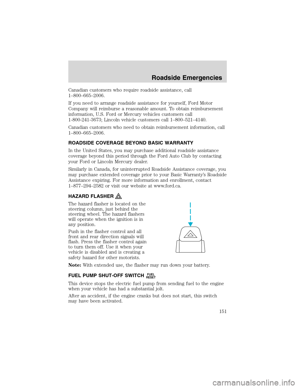
HAZARD FLASHER
The hazard flasher is located on the
steering column, just behind the
steering wheel. The hazard flashers
will operate when the ignition is in
any position.
Push in the flasher control and all
front and rear direction signals will
flash. Press the flasher control again
to turn them off. Use it when your
vehicle is disabled and is creating a
safety hazard for other motorists.
Note:With extended use, the flasher may run down your battery.
FUEL PUMP SHUT-OFF SWITCH
FUEL
RESET
This device stops the electric fuel pump from sending fuel to the engine
when your vehicle has had a substantial jolt.
After an accident, if the engine cranks but does not start, this switch
may have been activated.
Roadside Emergencies
151
Page 152 of 240
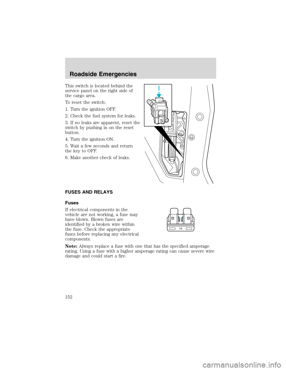
This switch is located behind the
service panel on the right side of
the cargo area.
To reset the switch:
1. Turn the ignition OFF.
2. Check the fuel system for leaks.
3. If no leaks are apparent, reset the
switch by pushing in on the reset
button.
4. Turn the ignition ON.
5. Wait a few seconds and return
the key to OFF.
6. Make another check of leaks.
FUSES AND RELAYS
Fuses
If electrical components in the
vehicle are not working, a fuse may
have blown. Blown fuses are
identified by a broken wire within
the fuse. Check the appropriate
fuses before replacing any electrical
components.
Note:Always replace a fuse with one that has the specified amperage
rating. Using a fuse with a higher amperage rating can cause severe wire
damage and could start a fire.
15
Roadside Emergencies
152
Page 154 of 240
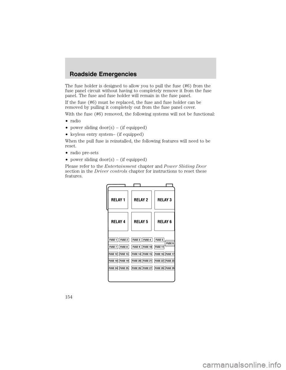
The fuse holder is designed to allow you to pull the fuse (#6) from the
fuse panel circuit without having to completely remove it from the fuse
panel. The fuse and fuse holder will remain in the fuse panel.
If the fuse (#6) must be replaced, the fuse and fuse holder can be
removed by pulling it completely out from the fuse panel cover.
With the fuse (#6) removed, the following systems will not be functional:
•radio
•power sliding door(s)–(if equipped)
•keyless entry system–(if equipped)
When the pull fuse is reinstalled, the following features will need to be
reset.
•radio pre-sets
•power sliding door(s)–(if equipped)
Please refer to theEntertainmentchapter andPower Sliding Door
section in theDriver controlschapter for instructions to reset these
features.
RELAY 1 RELAY 2 RELAY 3
RELAY 4 RELAY 5 RELAY 6
FUSE 1
FUSE 7
FUSE 12
FUSE 18
FUSE 24FUSE 8
FUSE 13
FUSE 19
FUSE 25FUSE 9
FUSE 14
FUSE 20
FUSE 26FUSE 10
FUSE 15
FUSE 21
FUSE 27FUSE 11
FUSE 16
FUSE 22
FUSE 28FUSE 17
FUSE 23
FUSE 29 FUSE 2 FUSE 3 FUSE 4 FUSE 5
FUSE 6
Roadside Emergencies
154
Page 196 of 240
7. Drive the vehicle to complete the relearning process.
•The vehicle may need to be driven 16 km (10 miles) or more to
relearn the idle and fuel trim strategy.
•If you do not allow the engine to relearn its idle trim, the idle
quality of your vehicle may be adversely affected until the idle
trim is eventually relearned.
If the battery has been disconnected or a new battery has been installed,
the clock and the preset radio stations must be reset once the battery is
reconnected.
If the battery has been discharged, disconnected or a new battery has
been installed, the power sliding door may need to be reset. Refer to
Power Sliding Door-Resetting the PSDin theControls and Features
chapter.
•Always dispose of automotive
batteries in a responsible manner.
Follow your local authorized
standards for disposal. Call your
local authorized recycling center
to find out more about recycling
automotive batteries.
ENGINE COOLANT
Checking engine coolant
The concentration and level of engine coolant should be checked at the
mileage intervals listed in the scheduled maintenance guide. The coolant
concentration should be maintained at 50/50 coolant and distilled water,
which equates to a freeze point of -36°C (-34°F). Coolant concentration
testing is possible with a hydrometer or antifreeze tester (such as the
Rotunda Battery and Antifreeze Tester, 014–R1060). The level of coolant
should be maintained at the“cold full”of“cold fill range”level in the
coolant reservoir. If the level falls below, add coolant per the instructions
in theAdding engine coolantsection.
Your vehicle was factory-filled with a 50/50 engine coolant and water
concentration. If the concentration of coolant falls below 40% or above
60%, the engine parts could become damaged or not work properly.A
50–50 mixture of coolant and water provides the following:
LEAD
RETURN
RECYCLE
Maintenance and Specifications
196