2003 FORD SUPER DUTY sensor
[x] Cancel search: sensorPage 80 of 256
Never place your arm over the air bag module as a deploying air
bag can result in serious arm fractures or other injuries.
To properlyposition yourself awayfrom the air bag:
•Move your seat to the rear as far as you can while still reaching the
pedals comfortably.
•Recline the seat slightlyone or two degrees from the upright position.
Do not put anything on or over the air bag module. Placing
objects on or over the air bag inflation area maycause those
objects to be propelled bythe air bag into your face and torso causing
serious injury.
Do not attempt to service, repair, or modifythe air bag
supplemental restraint systems or its fuses. See your Ford or
Lincoln Mercurydealer.
The front passenger air bag is not designed to offer protection to
an occupant in the center front seating position.
Modifying or adding equipment to the front end of the vehicle
(including frame, bumper, front end bodystructure and tow
hooks) mayaffect the performance of the air bag system, increasing
the risk of injury. Do not modify the front end of the vehicle.
Additional equipment such as snowplow equipment mayeffect
the performance of the air bag sensors increasing the risk of
injury. Please refer to the Body Builders Lay out Book for instructions
about the appropriate installation of additional equipment.
Removing the blocker beam without installing snow plow
attachment hardware mayeffect air bag deployment in a crash.
Do not operate the truck unless either the blocker beam or snow plow
attachment hardware is installed on the vehicle.
Children and air bags
For additional important safetyinformation, read all information on
safetyrestraints in this guide.
Seating and Safety Restraints
80
Page 82 of 256
restrained or are otherwise out of position at the time of air bag
deployment. Thus, it is extremely important that occupants be properly
restrained as far awayfrom the air bag module as possible while
maintaining vehicle control.
Several air bag system components get hot after inflation. Do not
touch them after inflation.
If the air bag has deployed,the air bag will not function
again and must be replaced immediately.If the air bag is not
replaced, the unrepaired area will increase the risk of injuryin a
collision.
The SRS consists of:
•driver and passenger (if equipped) air bag modules (which include the
inflators and air bags),
•one or more impact and safing sensors,
•a readiness light and tone
•and the electrical wiring which connects the components.
The diagnostic module monitors its own internal circuits and the
supplemental air bag electrical system warning (including the impact
sensors), the system wiring, the air bag system readiness light, the air
bag back up power and the air bag ignitors.
Determining if the system is operational
The SRS uses a readiness light in the instrument cluster or a tone to
indicate the condition of the system. Refer toAir bag readinesssection
in theInstrument clusterchapter. Routine maintenance of the air bag is
not required.
A difficultywith the system is indicated byone or more of the following:
•The readiness light will either
flash or staylit.
•The readiness light will not
illuminate immediatelyafter
ignition is turned on.
•A series of five beeps will be heard. The tone pattern will repeat
periodicallyuntil the problem and/or light are repaired.
Seating and Safety Restraints
82
Page 112 of 256
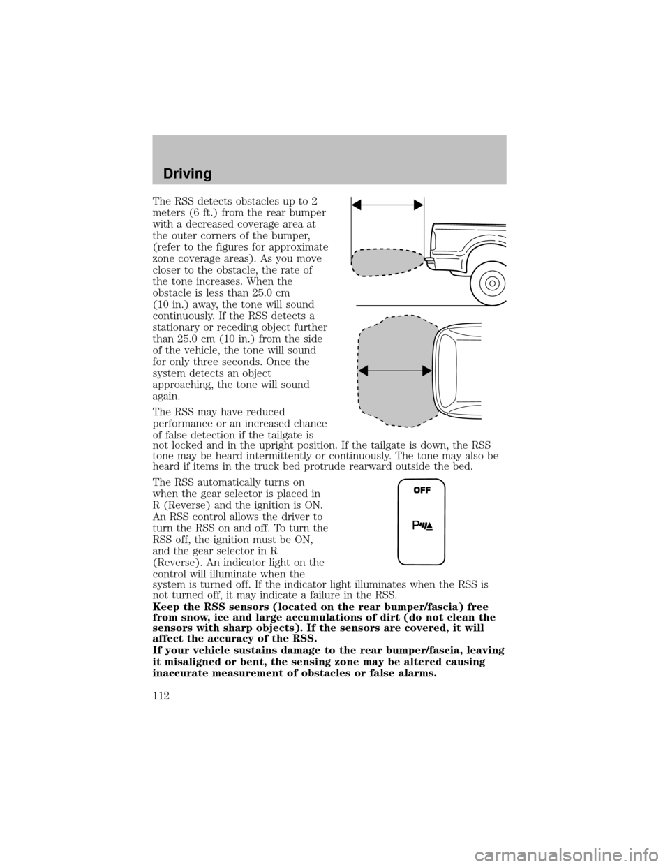
The RSS detects obstacles up to 2
meters (6 ft.) from the rear bumper
with a decreased coverage area at
the outer corners of the bumper,
(refer to the figures for approximate
zone coverage areas). As you move
closer to the obstacle, the rate of
the tone increases. When the
obstacle is less than 25.0 cm
(10 in.) away, the tone will sound
continuously. If the RSS detects a
stationaryor receding object further
than 25.0 cm (10 in.) from the side
of the vehicle, the tone will sound
for onlythree seconds. Once the
system detects an object
approaching, the tone will sound
again.
The RSS mayhave reduced
performance or an increased chance
of false detection if the tailgate is
not locked and in the upright position. If the tailgate is down, the RSS
tone maybe heard intermittentlyor continuously. The tone mayalso be
heard if items in the truck bed protrude rearward outside the bed.
The RSS automaticallyturns on
when the gear selector is placed in
R (Reverse) and the ignition is ON.
An RSS control allows the driver to
turn the RSS on and off. To turn the
RSS off, the ignition must be ON,
and the gear selector in R
(Reverse). An indicator light on the
control will illuminate when the
system is turned off. If the indicator light illuminates when the RSS is
not turned off, it mayindicate a failure in the RSS.
Keep the RSS sensors (located on the rear bumper/fascia) free
from snow, ice and large accumulations of dirt (do not clean the
sensors with sharp objects). If the sensors are covered, it will
affect the accuracy of the RSS.
If your vehicle sustains damage to the rear bumper/fascia, leaving
it misaligned or bent, the sensing zone may be altered causing
inaccurate measurement of obstacles or false alarms.
OFF
Driving
112
Page 151 of 256
Additional equipment such as snowplow equipment mayeffect
the performance of the air bag sensors increasing the risk of
injury. Please refer to the Body Builders Lay out Book for instructions
about the appropriate installation of additional equipment.
Engine temperature while plowing
When driving with a snowplow, your engine may run at a higher
temperature than normal because the attached snowplow blade will
restrict airflow to the radiator.
If you are driving more than 24 km (15 miles) at temperatures above
freezing, angle the plow blade either full left or full right to provide
maximum airflow to the radiator.
If you are driving less than 24 km (15 miles) at speeds up to 64 km/h
(40 mph) in cold weather, you will not need to worry about blade
position to provide maximum airflow.
4WD operation while plowing
•Shift transfer case to 4x4 LOW (4WD Low) when plowing in small
areas at speeds below 8 km/h (5 mph).
•Shift transfer case to 4x4 HIGH (4WD High) when plowing larger
areas or light snow at higher speeds. Do not exceed 24 km/h
(15 mph).
•Do not shift the transmission from a forward gear to R (Reverse) until
the engine is at idle and the wheels are stopped.
•If the vehicle is stuck, shift the transmission in a steadymotion
between forward and reverse gears. Do not rock the vehicle for more
than a few minutes. The transmission and tires maybe damaged or
the engine can overheat.
It is the owner’s responsibility to avoid engine overheating which
can cause damage.
Refer toTransmission temperature gaugein theInstrument cluster
chapter for transmission fluid temperature information.
Do not spin the wheels at over 35 mph (55 km/h). The tires may
fail and injure a passenger or bystander.
Driving
151
Page 157 of 256
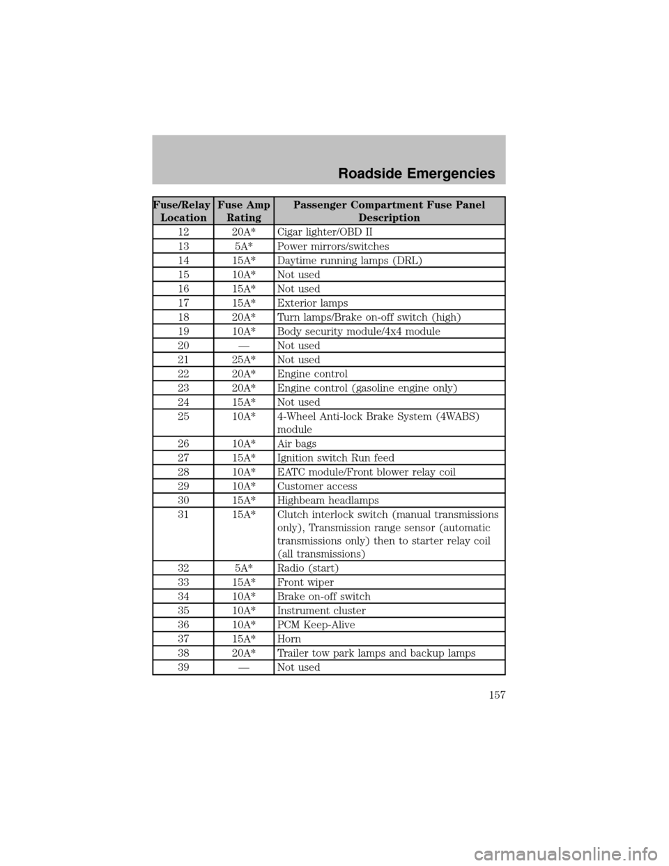
Fuse/Relay
LocationFuse Amp
RatingPassenger Compartment Fuse Panel
Description
12 20A* Cigar lighter/OBD II
13 5A* Power mirrors/switches
14 15A* Daytime running lamps (DRL)
15 10A* Not used
16 15A* Not used
17 15A* Exterior lamps
18 20A* Turn lamps/Brake on-off switch (high)
19 10A* Bodysecuritymodule/4x4 module
20 — Not used
21 25A* Not used
22 20A* Engine control
23 20A* Engine control (gasoline engine only)
24 15A* Not used
25 10A* 4-Wheel Anti-lock Brake System (4WABS)
module
26 10A* Air bags
27 15A* Ignition switch Run feed
28 10A* EATC module/Front blower relaycoil
29 10A* Customer access
30 15A* Highbeam headlamps
31 15A* Clutch interlock switch (manual transmissions
only), Transmission range sensor (automatic
transmissions only) then to starter relay coil
(all transmissions)
32 5A* Radio (start)
33 15A* Front wiper
34 10A* Brake on-off switch
35 10A* Instrument cluster
36 10A* PCM Keep-Alive
37 15A* Horn
38 20A* Trailer tow park lamps and backup lamps
39 — Not used
Roadside Emergencies
157