Page 3717 of 4378

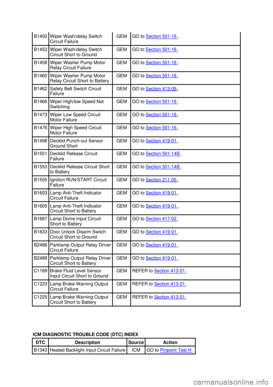
B1450 Wiper Wash/delay Switch
Circuit Failure GEM GO to
Section 501 - 16 .
B1453 Wiper Wash/delay Switch
Circuit Short to Ground GEM GO to
Section 501 - 16 .
B1458 Wiper Washer Pump Motor
Relay Circuit Failure GEM GO to
Section 501 - 16 .
B1460 Wiper Washer Pump Motor
Relay Circuit Short to Battery GEM GO to
Section 501 - 16 .
B1462 Safety Belt Switch Circuit
Failure GEM GO to
Section 413 - 09 .
B1466 Wiper High/low Speed Not
Switching GEM GO to
Section 501 - 16 .
B1473 Wiper Low Speed Circuit
Motor Failure GEM GO to
Section 501 - 16 .
B1476 Wiper High Speed Circuit
Motor Failure GEM GO to
Section 501 - 16 .
B1498 Decklid Punch-
out Sensor
Ground Short GEM GO to
Section 419 - 01 .
B1551 Decklid Release Circuit
Failure GEM GO to
Section 501 - 14B .
B1553 Decklid Release Circuit Short
to Battery GEM GO to
Section 501 - 14B .
B1555 Ignition RUN/START Circuit
Failure GEM GO to
Section 211 - 05 .
B1603 Lamp Anti-
Theft Indicator
Circuit Failure GEM GO to
Section 419 - 01 .
B1605 Lamp Anti-
Theft Indicator
Circuit Short to Battery GEM GO to
Section 419 - 01 .
B1687 Lamp Dome Input Circuit
Short to Battery GEM GO to
Section 417 - 02 .
B1833 Door Unlock Disarm Switch
Circuit Short to Ground GEM GO to
Section 419 - 01 .
B2486 Parklamp Output Relay Driver
Circuit Failure GEM GO to
Section 419 - 01 .
B2488 Parklamp Output Relay Driver
Circuit Short to Battery GEM GO to
Section 419 - 01 .
C1189 Brake Fluid Level Sensor
Input Circuit Short to Ground GEM REFER to
Section 413 - 01 .
C1223 Lamp Brake Warning Output
Circuit Failure GEM REFER to
Section 413 - 01 .
C1225 Lamp Brake Warning Output
Circuit Short to Battery GEM REFER to
Section 413 - 01 .
ICM DIAGNOSTIC TROUBLE CODE (DTC) INDEX DTC Description Source Action
B1343 Heated Backlight Input Circuit Failure ICM GO to
Pinpoint Test H . �K�l�j . 4 �b�a
322003 Mustang Workshop Manual
18. 11. 2011file:///C:/Ford/2000 - 2004/tsocache/SHEF_5108/S3B~us~en~ ...
Page 3761 of 4378

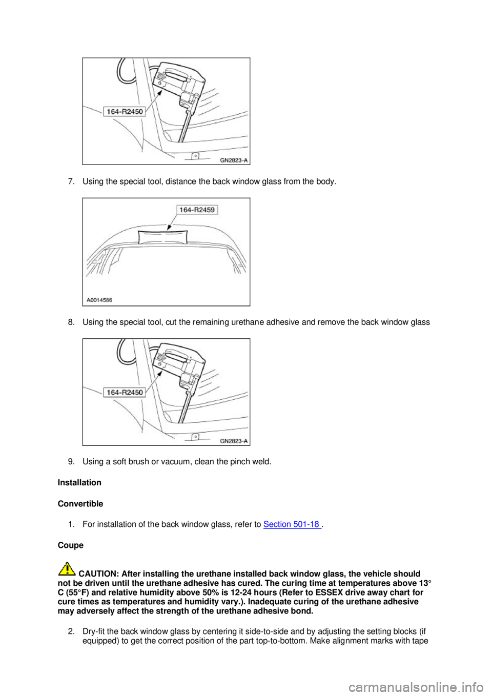
7. Using the special tool, distance the back window glass from the body.
8. Using the special tool, cut the remaining urethane adhesive and remove the back window glass
9. Using a soft brush or vacuum, clean the pinch weld.
Installation
Convertible 1. For installation of the back window glass, refer to Section 501 - 18 .
Coupe
CAUTION: After installing the urethane installed back window glass, the vehicle should
not be driven until the urethane adhesive has cured. The curing time at temperatures above 13°
C (55°F) and relative humidity above 50% is 12- 24 hours (Refer to ESSEX drive away chart for
cure times as temperatures and humidity vary.). Inadequate curing of the urethane adhesive
may adversely affect the strength of the urethane adhesive bond.
2. Dry-fit the back window glass by centering it side- to-side and by adjusting the setting blocks (if
equipped) to get the correct position of the part top- to-bottom. Make alignment marks with tape �K�l�j . 2 �b�a
42003 Mustang Workshop Manual
18. 11. 2011file:///C:/Ford/2000 - 2004/tsocache/SHEF_5108/S3B~us~en~ ...
Page 3783 of 4378

17. Using the special tool cut the urethane adhesive and remove the windshield.
18. Using a soft brush or vacuum, remove any dirt or foreign material from the pinch weld.
Installation
All vehicles
CAUTION: After installing the urethane installed windshield, the vehicle should not be
driven until the urethane adhesive has cured. The curing time at temperatures above 13°C (55°
F) and relative humidity above 50% is 12- 24 hours (Refer to ESSEX drive away chart for cure
times as temperatures and humidity vary). Inadequate curing of the urethane adhesive may
adversely affect the strength of the urethane adhesive bond.
1. Dry-fit the windshield glass by centering it side- to-side and by adjusting the setting blocks (if
equipped) to get the correct position of the part top- to-bottom. Make alignment marks with tape
or non- staining grease pencil on both the glass and the vehicle body.
2. CAUTION: Care must be taken to avoid scratching the pinch weld.
Trim the remaining urethane on the pinch weld using only the full- cut method. in this method,
most of the existing urethane is removed leaving a level bead around the entire pinch weld. �K�l�j . 5 �b�a
102003 Mustang Workshop Manual
18. 11. 2011file:///C:/Ford/2000 - 2004/tsocache/SHEF_5108/S3B~us~en~ ...
Page 3797 of 4378
2. Separate the intermediate shaft from the steering column shaft.
22. NOTE: The corner of the carpet may have to be pulled back slightly to carry out this step.
Disconnect the LH main wiring harness electrical connectors.
23. Disconnect the generic electronic module (GEM) electrical connectors.
24. Disconnect the electronic crash sensor (ECS) module electrical connector. 1. Release the locking tab.
2. Disconnect the ECS module electrical connector. �K�l�j . 5 �b�a
152003 Mustang Workshop Manual
18. 11. 2011file:///C:/Ford/2000 - 2004/tsocache/SHEF_5108/S3B~us~en~ ...
Page 3798 of 4378
25. If equipped, disconnect the shift interlock assembly from the selector lever.
1. Remove the screw.
2. Remove the R- clip.
3. Disconnect the shift interlock cable.
4. Disconnect the shift interlock assembly from the selector lever.
26. Remove the audio unit. For additional information, refer to Section 415 - 01 .
27. If equipped, disconnect the shifter assembly electrical connector.
28. NOTE: This step is being carried out through the audio unit opening.
NOTE: Rotate the temperature control switch to the cool position.
Release the temperature control cable from the blend door.
29. Remove the four center instrument panel support bolts. �K�l�j . 6 �b�a
152003 Mustang Workshop Manual
18. 11. 2011file:///C:/Ford/2000 - 2004/tsocache/SHEF_5108/S3B~us~en~ ...
Page 3802 of 4378
9. Install the audio unit. For additional information, refer to
Section 415 - 01 .
10. If equipped, connect the shift interlock assembly to the selector lever. 1. Position the shift interlock assembly.
2. Connect the shift interlock cable.
3. Install the R- clip.
4. Install the screw.
11. Connect the ECS module electrical connector. 1. Connect the ECS module electrical connector.
2. Engage the locking tab.
12. Connect the GEM electrical connectors. �K�l�j . 10 �b�a
152003 Mustang Workshop Manual
18. 11. 2011file:///C:/Ford/2000 - 2004/tsocache/SHEF_5108/S3B~us~en~ ...
Page 3812 of 4378
SPECIFICATIONS
SECTION 501-
14A: Handles, Locks, Latches and Mechanisms 2003 Mustang Workshop Manual General Specifications
Item Specification
Lubricants
Multi-
Purpose Grease Spray
F5AZ- 19G209- AA ESR-
M1C159- A Penetrating and Lock Lubricant
E8AZ-
19A501- B —
Torque Specifications Description Nm lb-
ft lb-
in Door latch screws 12 9 —
Luggage compartment lid screws 9 — 80
Exterior door handle nuts 9 — 80
Luggage compartment lid latch striker screws 12 9 —
Fuel tank filler door retaining screws 3 — 27
Door latch striker plate screws 25 18 —
LOCK REPAIR/REPLACEMENT SPECIFICATIONS Part Number Lock Repair Package Name
F85Z-
11582- AA Ignition Cylinder
F8ZZ-
6321990- AA Door Lock
XR32-
6343262- BA Luggage Compartment Lid
Luggage Compartment Lid, Remote
F8DZ-
5406082- AA Glove Box
F8DZ-
5421970- AA Lock Lever Kit �K�l�j . 1 �b�a
22003 Mustang Workshop Manual
18. 11. 2011file:///C:/Ford/2000 - 2004/tsocache/SHEF_5108/S3B~us~en~ ...
Page 3814 of 4378

DESCRIPTION AND OPERATION
Handles, Locks, Latches And Mechanisms
Lock Cylinders
Individual lock cylinders are repaired by discarding the inoperative lock cylinder and building a new
lock cylinder using the appropriate lock repair package. The lock repair package includes a detailed
instruction sheet to build the new lock cylinder to the current key code of the vehicle.
Latch System
The door latch system consists of:
�zfront door latch remote control and cable assembly
�z front door latch (21812)
�z door latch control rod knob (21850)
�z door handle (22404) and front door latch actuating rod (22152)
�z lock cylinder (22050) and front door latch control cylinder rod (22134)
�z door latch striker plate (22008)
�z front door latch remote control cable (221A00)
�z door lock cylinder (21990)
�z window regulator switch plates (14524)
�z adjunct actuator (218B20)
�z circuit wiring and circuit protection
�z front door lock switch (14017)
�z luggage compartment lid latch with mechanical interior release handle and cable
�z luggage compartment lid lock cylinder
Refer to Section 501 - 14B .
Luggage Compartment Lid Remote Control Lock Switch
The luggage compartment remote control system consists of:
�zluggage compartment remote control lock switch (19C542) located in the glove compartment
(06010)
�z remote control lock actuator (part of the luggage compartment lid latch)
�z circuit wiring and circuit protection
Refer to Section 501 - 14B .
SECTION 501-
14A: Handles, Locks, Latches and Mechanisms 2003 Mustang Workshop Manual �K�l�j . 1 �b�a
22003 Mustang Workshop Manual
18. 11. 2011file:///C:/Ford/2000 - 2004/tsocache/SHEF_5108/S3B~us~en~ ...