Page 2955 of 4378
SPECIFICATIONS
SECTION 310-
00: Fuel System — General Information 2003 Mustang Workshop Manual General Specifications
Item Specification
Fuel tank capacity 59.42 liters (15.7 gallons)
Key on, engine off fuel pressure 207-
345 kPa
(30-50 psi) Engine running fuel pressure (idle) 152-
255 kPa
(27-37 psi) Lubricants
SAE 5W-
20 Super Premium Synthetic Blend Motor Oil XO-5W20- QSP WSS-
M2C153- H �K�l�j . 1 �b�a
12003 Mustang Workshop Manual
18. 11. 2011file:///C:/Ford/2000 - 2004/tsocache/SHEF_2308/S3B~us~en~ ...
Page 3037 of 4378

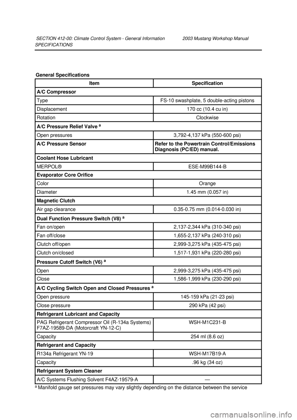
SPECIFICATIONS
a
Manifold gauge set pressures may vary slightly depending on the distance between the service
SECTION 412-
00: Climate Control System - General Information 2003 Mustang Workshop Manual General Specifications
Item Specification
A/C Compressor
Type FS-
10 swashplate, 5 double- acting pistons Displacement 170 cc (10.4 cu in)
Rotation Clockwise
A/C Pressure Relief Valve
a Open pressures 3,792-
4,137 kPa (550- 600 psi) A/C Pressure Sensor Refer to the Powertrain Control/Emissions
Diagnosis (PC/ED) manual.
Coolant Hose Lubricant
MERPOL® ESE-
M99B144- B Evaporator Core Orifice
Color Orange
Diameter 1.45 mm (0.057 in)
Magnetic Clutch
Air gap clearance 0.35-
0.75 mm (0.014- 0.030 in) Dual Function Pressure Switch (V8)
a Fan on/open 2,137-
2,344 kPa (310- 340 psi) Fan off/close 1,655-
2,137 kPa (240- 310 psi) Clutch off/open 2,999-
3,275 kPa (435- 475 psi) Clutch on/closed 1,517-
1,931 kPa (220- 280 psi) Pressure Cutoff Switch (V6)
a Open 2,999-
3,275 kPa (435- 475 psi) Close 1,586-
1,999 kPa (230- 290 psi) A/C Cycling Switch Open and Closed Pressures
a Open pressure 145-
159 kPa (21- 23 psi) Close pressure 290 kPa (42 psi)
Refrigerant Lubricant and Capacity
PAG Refrigerant Compressor Oil (R-134a Systems)
F7AZ- 19589- DA (Motorcraft YN-12- C) WSH-
M1C231- B Capacity 254 ml (8.6 oz)
Refrigerant and Capacity
R134a Refrigerant YN-
19 WSH-
M17B19- A Capacity .96 kg (34 oz)
Refrigerant System Cleaner
A/C Systems Flushing Solvent F4AZ-19579-
A — �K�l�j . 1 �b�a
22003 Mustang Workshop Manual
18. 11. 2011file:///C:/Ford/2000 - 2004/tsocache/SHEF_2308/S3B~us~en~ ...
Page 3265 of 4378

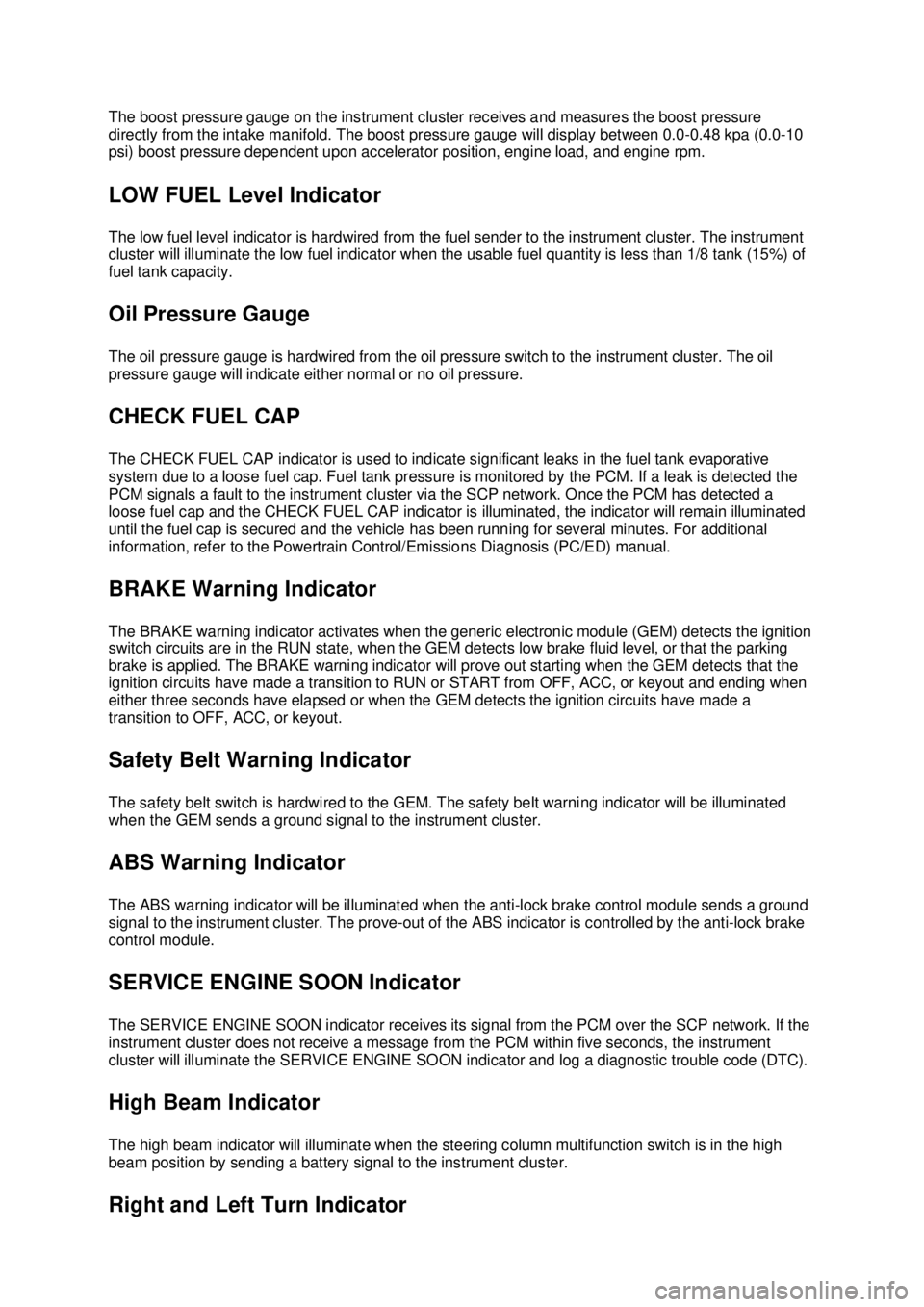
The boost pressure gauge on the instrument cluster receives and measures the boost pressure
directly from the intake manifold. The boost pressure gauge will display between 0.0-
0.48 kpa (0.0-10
psi) boost pressure dependent upon accelerator position, engine load, and engine rpm.
LOW FUEL Level Indicator
The low fuel level indicator is hardwired from the fuel sender to the instrument cluster. The instrument
cluster will illuminate the low fuel indicator when the usable fuel quantity is less than 1/8 tank (15%) of
fuel tank capacity.
Oil Pressure Gauge
The oil pressure gauge is hardwired from the oil pressure switch to the instrument cluster. The oil
pressure gauge will indicate either normal or no oil pressure.
CHECK FUEL CAP
The CHECK FUEL CAP indicator is used to indicate significant leaks in the fuel tank evaporative
system due to a loose fuel cap. Fuel tank pressure is monitored by the PCM. If a leak is detected the
PCM signals a fault to the instrument cluster via the SCP network. Once the PCM has detected a
loose fuel cap and the CHECK FUEL CAP indicator is illuminated, the indicator will remain illuminated
until the fuel cap is secured and the vehicle has been running for several minutes. For additional
information, refer to the Powertrain Control/Emissions Diagnosis (PC/ED) manual.
BRAKE Warning Indicator
The BRAKE warning indicator activates when the generic electronic module (GEM) detects the ignition
switch circuits are in the RUN state, when the GEM detects low brake fluid level, or that the parking
brake is applied. The BRAKE warning indicator will prove out starting when the GEM detects that the
ignition circuits have made a transition to RUN or START from OFF, ACC, or keyout and ending when
either three seconds have elapsed or when the GEM detects the ignition circuits have made a
transition to OFF, ACC, or keyout.
Safety Belt Warning Indicator
The safety belt switch is hardwired to the GEM. The safety belt warning indicator will be illuminated
when the GEM sends a ground signal to the instrument cluster.
ABS Warning Indicator
The ABS warning indicator will be illuminated when the anti- lock brake control module sends a ground
signal to the instrument cluster. The prove- out of the ABS indicator is controlled by the anti- lock brake
control module.
SERVICE ENGINE SOON Indicator
The SERVICE ENGINE SOON indicator receives its signal from the PCM over the SCP network. If the
instrument cluster does not receive a message from the PCM within five seconds, the instrument
cluster will illuminate the SERVICE ENGINE SOON indicator and log a diagnostic trouble code (DTC).
High Beam Indicator
The high beam indicator will illuminate when the steering column multifunction switch is in the high
beam position by sending a battery signal to the instrument cluster. Right and Left Turn Indicator �K�l�j . 3 �b�a
412003 Mustang Workshop Manual
18. 11. 2011file:///C:/Ford/2000 - 2004/tsocache/SHEF_5108/S3B~us~en~ ...