Page 2023 of 4378
REMOVAL AND INSTALLATION
Accessory Drive Belt Tensioner —
4.6L (2V) and (4V)
Removal and Installation
Mach I 1. Remove the air intake scoop. For additional information, refer to Section 303 - 12 .
Cobra 2. Remove the supercharger drive belt cover.
3. Rotate the supercharger belt tensioner clockwise and remove the supercharger belt.
4. Remove the cooling hose and tube assembly mounting bolt.
5. Remove the belt idler support bracket assembly.
SECTION 303-
05: Accessory Drive 2003 Mustang Workshop Manual �K�l�j . 1 �b�a
32003 Mustang Workshop Manual
18. 11. 2011file:///C:/Ford/2000 - 2004/tsocache/SHEF_4464/S3B~us~en~ ...
Page 2143 of 4378
40.
NOTE: Inspect the intake manifold gaskets and install new gaskets, if necessary.
Tighten the lower intake manifold bolts in the sequence shown.
41. Fill and bleed the supercharger cooling system. For additional information, refer to Section 303 -
03B . �K�l�j . 10 �b�a
102003 Mustang Workshop Manual
18. 11. 2011file:///C:/Ford/2000 - 2004/tsocache/SHEF_4464/S3B~us~en~ ...
Page 2205 of 4378
REMOVAL AND INSTALLATION
Intake Manifold Runner Control (IMRC) Actuator —
3.8L
Removal and Installation 1. Disconnect the battery ground cable. For additional information, refer to Section 414 - 01 .
2. Drain the cooling system. For additional information, refer to Section 303 - 03A .
3. Remove the upper intake manifold. For additional information, refer to Section 303 - 01A .
4. Remove the fuel injector supply manifold. For additional information, refer to Section 303 - 04A .
5. Remove the coolant bypass tube. For additional information, refer to Section 303 - 03A .
6. Remove the bolt and heater water inlet tube at the back of the lower intake.
7. Remove the two stud bolts and one bolt. Position the actuator aside.
8. Disconnect the linkage and remove the actuator.
SECTION 303-
14: Electronic Engine Controls 2003 Mustang Workshop Manual �K�l�j . 1 �b�a
22003 Mustang Workshop Manual
18. 11. 2011file:///C:/Ford/2000 - 2004/tsocache/SHEF_4464/S3B~us~en~ ...
Page 2228 of 4378
REMOVAL AND INSTALLATION
Engine Coolant Temperature (ECT) Sensor —
4.6L (2V)
Removal 1. Disconnect the battery ground cable. For additional information, refer to Section 414 - 01 .
2. Partially drain the cooling system. For additional information, refer to Section 303 - 03A .
3. Disconnect the engine coolant temperature (ECT) sensor (12A648) connector.
4. Remove the ECT sensor.
Installation 1. To install, reverse the removal procedure.
SECTION 303-
14: Electronic Engine Controls 2003 Mustang Workshop Manual �K�l�j . 1 �b�a
22003 Mustang Workshop Manual
18. 11. 2011file:///C:/Ford/2000 - 2004/tsocache/SHEF_4464/S3B~us~en~ ...
Page 2230 of 4378
REMOVAL AND INSTALLATION
Engine Coolant Temperature (ECT) Sensor —
Cobra
Removal and Installation 1. Partially drain the engine cooling system. For additional information, refer to Section 303 - 03A .
2. Disconnect the engine coolant temperature (ECT) sensor electrical connector.
3. Remove the ECT sensor.
4. To install, reverse the removal procedure. �zApply sealant to the ECT sensor threads.
SECTION 303-
14: Electronic Engine Controls 2003 Mustang Workshop Manual Material
Item Specification
Pipe Sealant with Teflon
D8AZ-
19554- A WSK-
M2G350- A2 �K�l�j . 1 �b�a
22003 Mustang Workshop Manual
18. 11. 2011file:///C:/Ford/2000 - 2004/tsocache/SHEF_4464/S3B~us~en~ ...
Page 2232 of 4378
REMOVAL AND INSTALLATION
Engine Coolant Temperature (ECT) Sensor —
Mach I
Removal and Installation 1. Remove the air intake scoop. For additional information, refer to Section 303 - 12 .
2. Partially drain the engine cooling system. For additional information, refer to Section 303 - 03A .
3. Disconnect the engine coolant temperature (ECT) sensor electrical connector.
4. Remove the ECT sensor.
5. To install, reverse the removal procedure. �zApply sealant to the ECT sensor threads.
SECTION 303-
14: Electronic Engine Controls 2003 Mustang Workshop Manual Material
Item Specification
Pipe Sealant with Teflon
D8AZ-
19554- A WSK-
M2G350- A2 �K�l�j . 1 �b�a
22003 Mustang Workshop Manual
18. 11. 2011file:///C:/Ford/2000 - 2004/tsocache/SHEF_4464/S3B~us~en~ ...
Page 2294 of 4378

The transmission uses a gerotor-
type design front pump support and gear. The pump provides the
volume of fluid needed to charge the torque converter, main control assembly, cooling system and
lube system. Pump pressure is regulated by the main regulator valve. The pump has an internal boost
circuit which is more efficient at lower engine speeds.
Filter
All fluid drawn from the transmission pan by the pump passes through the filter. The filter and its
accompanying seal are part of the fluid path from the sump (pan) to the fluid pump.
Main Control
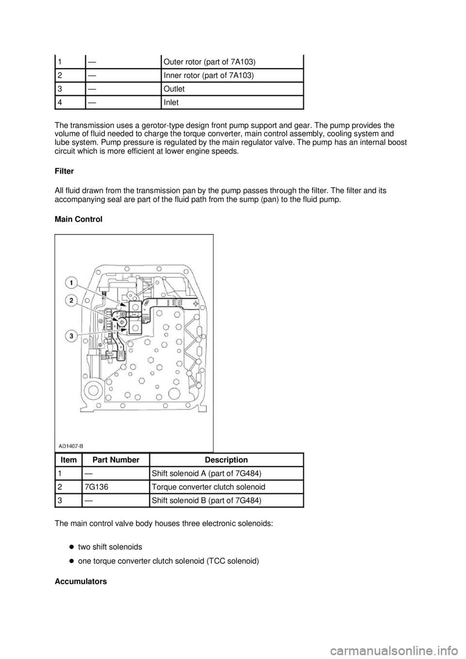
The main control valve body houses three electronic solenoids:
�ztwo shift solenoids
�z one torque converter clutch solenoid (TCC solenoid) Accumulators 1 — Outer rotor (part of 7A103)
2 — Inner rotor (part of 7A103)
3 — Outlet
4 — Inlet
Item Part Number Description
1 — Shift solenoid A (part of 7G484)
2 7G136 Torque converter clutch solenoid
3 — Shift solenoid B (part of 7G484) �K�l�j . 2 �b�a
42003 Mustang Workshop Manual
18. 11. 2011file:///C:/Ford/2000 - 2004/tsocache/SHEF_2748/S3B~us~en~ ...
Page 2297 of 4378

DESCRIPTION AND OPERATION
Transmission Electronic Control System
The powertrain control module (PCM) and its input/output network control the following transmission
operations:
�zShift timing
�z Line pressure (shift feel)
�z Torque converter clutch
The transmission control is separate from the engine control strategy in the PCM, although some of
the input signals are shared. When determining the best operating strategy for transmission operation,
the PCM uses input information from certain engine- related and driver-demand related sensors and
switches.
In addition, the PCM receives input signals from certain transmission- related sensors and switches.
The PCM also uses these signals when determining transmission operating strategy.
Using all of these input signals, the PCM can determine when the time and conditions are right for a
shift, or when to apply or release the torque converter clutch (TCC). It will also determine the best line
pressure needed to optimize shift feel. To accomplish this, the PCM uses hydraulic solenoids to control
transmission operation.
The following provides a brief description of each of the sensors and actuators used to control
transmission operation.
Powertrain Control Module (PCM)
The operation of the transmission is controlled by the powertrain control module (PCM). Many input
sensors provide information to the PCM. The PCM then controls actuators which determine
transmission operation.
Air Conditioning (A/C) Clutch
An electromagnetic clutch is energized when the clutch cycling pressure switch closes. The switch is
located on the suction accumulator/drier. The closing of the switch completes the circuit to the clutch
and draws it into engagement with the compressor driveshaft. When the A/C clutch is engaged,
electronic pressure control (EPC) is adjusted by the PCM to compensate for additional load on the
engine.
Brake Pedal Position (BPP) Switch
The brake pedal position (BPP) switch tells the PCM when the brakes are applied. The torque
converter clutch disengages when the brakes are applied. The BPP switch closes when the brakes are
applied and opens when they are released.
Engine Coolant Temperature (ECT) Sensor
The engine coolant temperature (ECT) sensor detects temperature of engine coolant and supplies the
information to the powertrain control module. The ECT sensor is used to control torque converter
clutch (TCC) operation. The ECT is installed in the heater outlet fitting or cooling passage on the
engine. For engine control applications, the ECT signal is used to modify ignition timing, EGR flow and
air- to-fuel ratio as a function of engine coolant temperature.
SECTION 307-
01: Automatic Transaxle/Transmission 2003 Mustang Workshop Manual �K�l�j . 1 �b�a
42003 Mustang Workshop Manual
18. 11. 2011file:///C:/Ford/2000 - 2004/tsocache/SHEF_2748/S3B~us~en~ ...