Page 1 of 96
Introduction
3
Instrumentation
8
Warning and control lights 8
Gauges 11
Lights
14
Headlamps 14
Bulb replacement 15
Driver controls
16
Windshield wiper/washer control 16
Speed control (Cruise control) 17
Driving
20
Starting 20
Brakes 23
Transmission operation 27
Vehicle loading 31
Trailer towing 33
Roadside emergencies
36
Hazard flasher switch 36
Fuel pump shut-off switch 36
Fuses and relays 38
Changing tires 45
Jump starting 48
Wrecker towing 52
Table of contents
1
Page 10 of 96
Low fuel:Illuminates when the fuel
level in the fuel tank is at, or near
empty (refer toFuel gaugein this
chapter).
Fuel reset:Illuminates when the
fuel pump shut-off switch has been
triggered. For more information
refer toFuel pump shut-off switch
in theRoadside Emergencies
chapter.
Door ajar:Illuminates when the
ignition is in the ON position and
any door is open.
Turn signal:Illuminates when the
left or right turn signal or the
hazard lights are turned on. If the
indicators stay on or flash faster, check for a burned out bulb.
High beams:Illuminates when the
high beam headlamps are turned on.
Key-in-ignition warning chime:Sounds when the key is left in the
ignition in the OFF/LOCK or ACC position and the driver’s door is
opened.
Headlamps on warning chime:Sounds when the headlamps or parking
lamps are on, the ignition is off (and the key is not in the ignition) and
the driver’s door is opened.
LOW
FUEL
FUEL
RESET
DOOR
AJAR
Instrumentation
10
Page 14 of 96
HEADLAMP CONTROL
Turns the lamps off.
Turns on the parking lamps,
instrument panel lamps, license
plate lamps and tail lamps.
Turns the headlamps on.
Daytime running lamps (DRL) (if equipped)
The daytime running light system turns the headlamps on, with a
reduced light output, when:
•the vehicle is running and
•the headlamp system is in the OFF position or parking lamp position.
Always remember to turn on your headlamps at dusk or during
inclement weather. The Daytime Running Light (DRL) System
does not activate your tail lamps and generally may not provide
adequate lighting during these conditions. Failure to activate your
headlamps under these conditions may result in a collision.
High beams
Push the lever toward the
instrument panel to activate. Pull
the lever towards you to deactivate.
P
Lights
14
Page 15 of 96
Flash to pass
Pull toward you slightly to activate
and release to deactivate.
PANEL DIMMER CONTROL
Use to adjust the brightness of the
instrument panel and all applicable
switches in the vehicle during
headlamp and parklamp operation.
Move the control to the full upright
position, past detent, to turn on the
interior lamps.
Move the control to the full down
position, past detent, to prevent the interior lights from illuminating
when the doors are opened.
BULBS
Replacing exterior bulbs
Check the operation of all the bulbs frequently.PANEL
DIM
Lights
15
Page 21 of 96

Do not park, idle, or drive your vehicle in dry grass or other dry
ground cover. The emission system heats up the engine
compartment and exhaust system, which can start a fire.
Do not start your vehicle in a closed garage or in other enclosed
areas. Exhaust fumes can be toxic. Always open the garage door
before you start the engine. SeeGuarding against exhaust fumesin
this chapter for more instructions.
If you smell exhaust fumes inside your vehicle, have your dealer
inspect your vehicle immediately. Do not drive if you smell
exhaust fumes.
Important safety precautions
A computer system controls the engine’s idle revolutions per minute
(RPM). When the engine starts, the idle RPM runs higher than normal in
order to warm the engine. If the engine idle speed does not slow down
automatically, have the vehicle checked. Do not allow the vehicle to idle
for more than 10 minutes.
Before starting the vehicle:
1. Make sure all vehicle occupants have buckled their safety belts.
2. Make sure the headlamps and vehicle accessories are off.
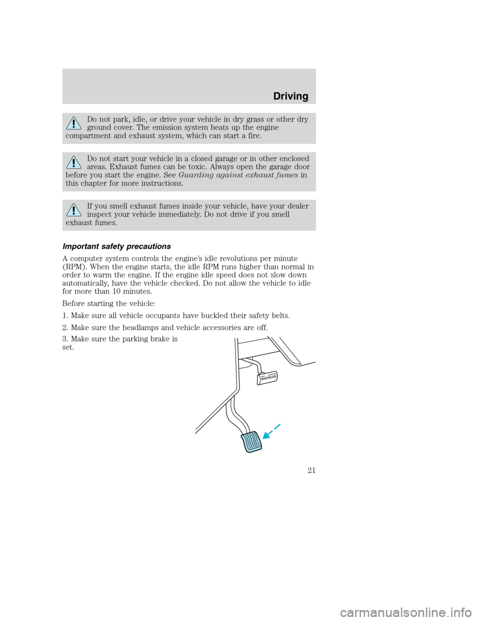
3. Make sure the parking brake is
set.
Driving
21
Page 40 of 96
Fuse/Relay
LocationFuse Amp
RatingPassenger Compartment Fuse
Panel Description
9 20A Stoplamps: Trailer tow Electric
Brake controller feed, Body
builder rear turn/stop feeds, Body
builder stop lamp feed, Trailer
turn/stop fuse feeds
10 5A Instrument cluster memory,
Power brake assist lamp*
11 30A Wiper/Washer module, Wiper feed
12 10A Trailer tow stop/turn feed
13 10A ABS module
14 10A Warning chime module, Power
brake assist module*, Instrument
cluster power, Instrument cluster
warning lamps, Transmission
control switch
15 15A Left turn signal feed
16 20A Body builder battery (+12V) feed
17 5A Body builder radio feed
18 — Not used
19 5A DRL relays
20 — Not used
21 15A Right turn signal feed
22 — Not used
23 — Not used
24 — Not used
25 10A Right-hand low beam headlamp
feed
26 10A Speed control module, Brake shift
interlock actuator
27 — Not used
28 — Not used
29 — Not used
Roadside emergencies
40
Page 41 of 96

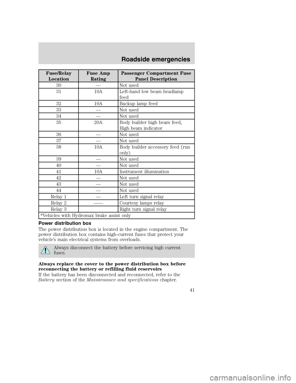
Fuse/Relay
LocationFuse Amp
RatingPassenger Compartment Fuse
Panel Description
30 — Not used
31 10A Left-hand low beam headlamp
feed
32 10A Backup lamp feed
33 — Not used
34 — Not used
35 20A Body builder high beam feed,
High beam indicator
36 — Not used
37 — Not used
38 10A Body builder accessory feed (run
only)
39 — Not used
40 — Not used
41 10A Instrument illumination
42 — Not used
43 — Not used
44 — Not used
Relay 1 — Left turn signal relay
Relay 2 —— Courtesy lamps relay
Relay 3 Right turn signal relay
*Vehicles with Hydromax brake assist only
Power distribution box
The power distribution box is located in the engine compartment. The
power distribution box contains high-current fuses that protect your
vehicle’s main electrical systems from overloads.
Always disconnect the battery before servicing high current
fuses.
Always replace the cover to the power distribution box before
reconnecting the battery or refilling fluid reservoirs
If the battery has been disconnected and reconnected, refer to the
Batterysection of theMaintenance and specificationschapter.
Roadside emergencies
41
Page 44 of 96
Fuse/Relay
LocationFuse Amp
RatingPower Distribution Box
Description
24 40A** IP battery feed (fuses #4, 10, 16)
25 50A** Ignition switch feed (IP fuses #1,
5, 7, 11, 13, 14, 17, 19, PDB fuses
#7, 9, 11)
26 60A** Ignition switch feed (IP fuses #5,
11, 17, 26, 32, 38)
27 30A** Multifunction switch (headlamps)
28 — Not used
29 60A** Power brake assist motor***
Relay 1 — DRL on/off relay
Relay 2 — Fuel pump relay
Relay 3 — Horn relay
Relay 4 — A/C system relay
Relay 5 — Blower motor relay
Relay 6 — PCM relay
Diode 1 — PCM diode
Diode 2 — Park brake diode
* Mini Fuses ** Maxi Fuses ***
Vehicles with Hydromax brake assist only
Relay module
The relay box is located by the power distribution box in front of the
radiator in the engine compartment.
The relays are coded as follows:
Relay location Description
1 Back up Lamp
2 Running Lamp
3 Not Used
4 Headlamp DRL
12 43
Roadside emergencies
44