Page 182 of 272
Fuse/Relay
LocationFuse Amp
RatingPassenger Compartment Fuse Panel
Description
26 7.5A Park aid, Brake shift interlock, Approach lamp
relay coil, IVD switch
27 7.5A Electrochromatic mirror, Digital transmission
range sensor - backup lamps
28 5A Radio (Start)/DVD (Start)
29 10A Digital transmission range sensor, PWR feed
to fuse #28 (Start feed)
30 5A Daytime Running Lamps (DRL), Remote
solenoid, DEATC climate controller, Manual
climate control, Manual climate control temp
blend actuator
Passenger compartment fuse panel (top side)
These relays are located on the reverse side of the passenger
compartment fuse panel. See your dealer or a certified technician for
service of this relay box.
Roadside Emergencies
182
Page 184 of 272
The high-current fuses are coded as follows:
Fuse/Relay
LocationFuse Amp
RatingPower Distribution Box Description
1 60A** PJB
2 30A** BSM
3—Not used
4 30A** Rear defrost
5 40A** Anti-lock Brake System (ABS) pump
6 60A** Delayed accessory
7 20A** Power point #2
8—Not used
9 20A** Power point #1
10 30A** ABS module (valves)
11 40A** PTEC
12 50A** Ignition relay, Starter relay
13 40A** Trailer tow battery, Trailer tow turn signals
14 10A* Daytime Running Lamps (DRL) (Canada)
15 15A* Memory (PCM/DEATC/Cluster)
16 15A* Headlamp switch, Foglamp switch
17 20A* 4x4 (v-batt 2)
18 20A* 4x4 (v-batt 1)
19 20A** High beam relay
Roadside Emergencies
184
Page 185 of 272
Fuse/Relay
LocationFuse Amp
RatingPower Distribution Box Description
20 30A** Electric brake
21 30A** Front wiper motor
22 20A** Low beam
23 30A** Ignition switch
24—Not used
25—Not used
26 15A* Fuel pump
27 20A* Trailer tow lamps
28 20A* Horn relay
29 60A** PJB
30 20A** Rear wiper motor
31—Not used
32—Not used
33 30A** Auxiliary blower motor
34 30A** Passenger power seat, Adjustable pedals
35—Not used
36 40A** Blower motor
37 15A* A/C clutch relay, Transmission
38 15A* Coil on plug
39 15A* Injectors, Fuel pump relay
40 15A* PTEC power
41 15A* HEGO, VMV, CMS, PTEC
42 10A* Right low beam
43 10A* Left low beam
44 15A* Front foglamps
45 2A* Brake pressure switch (ABS)
46 20A* High beams
47—Horn relay
48—Fuel pump relay
49—High beam relay
50—Fog lamp relay
Roadside Emergencies
185
Page 186 of 272
Fuse/Relay
LocationFuse Amp
RatingPower Distribution Box Description
51—DRL relay (Canada)/AdvanceTrac�relay
(U.S.)
52—A/C clutch relay
53—Trailer tow right turn relay
54—Trailer tow left turn relay
55—Blower motor relay
56—Starter relay
57—PTEC relay
58—Ignition relay
59—Driver brake applied relay (vehicles equipped
with AdvanceTrac�only)
60—PCM diode
61—A/C clutch diode
62 30A CB Power windows circuit breaker
* Mini Fuses ** Maxi Cartridge Fuses
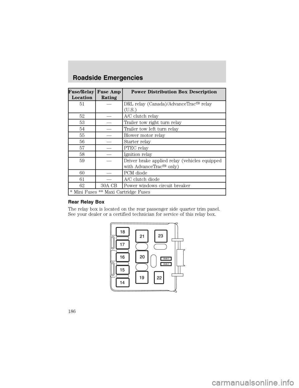
Rear Relay Box
The relay box is located on the rear passenger side quarter trim panel.
See your dealer or a certified technician for service of this relay box.
Roadside Emergencies
186
Page 188 of 272

The relays are coded as follows:
Fuse/Relay Location Description
Relay 64 AdvanceTrac�relay
Relay 65 Open
Relay 66 Open
CHANGING THE TIRES
If you get a flat tire while driving:
•do not brake heavily.
•gradually decrease the vehicle’s speed.
•hold the steering wheel firmly.
•slowly move to a safe place on the side of the road.
The use of tire sealants is not recommended and may
compromise the integrity of your tires. The use of tire sealants
may also affect your tire pressure monitoring system (if equipped).
If your vehicle is equipped with a tire pressure monitoring
system, refer toTire Pressure Monitoring System (if
equipped)in theMaintenance and specificationssection for
important information. If the tire pressure monitor sensor becomes
damaged, it will no longer function.
Spare tire information
The spare tire can be used as a spare or a regular tire and is identical to
the other tires on your vehicle.
If your vehicle is equipped with AWD, a spare tire of a different
size than the road tires should not be used. Such a tire could
make the vehicle difficult to control as well as result in damage to
driveline components.
Roadside Emergencies
188
Page 189 of 272

Stopping and securing the vehicle
1. If you get a flat tire while driving,
do not apply the brake heavily;
instead, gradually decrease your
speed. Hold the steering wheel
firmly and slowly move to a safe
place on the side of the road.
2. Park on a level surface, activate
the hazard flashers and set the
parking brake.
3. Place gearshift lever in P (Park)
and turn engine OFF.
When one of the rear wheels is off the ground, the transmission
alone will not prevent the vehicle from moving or slipping off the
jack, even if the transmission is in P (Park).
Note:Passengers should not remain
in the vehicle when the vehicle is
being jacked.
4. Block the wheel that is diagonally
opposite of the flat tire using the
wheel chock provided with your
vehicle.
Location of the spare tire and tools
The spare tire and tools for your vehicle are stowed in the following
locations:
Tool Location
Spare tire Under the vehicle, just in front of the
rear bumper. The spare tire winch drive
nut is located at the rear center of the
cargo area under a lid.
Jack, lug nut wrench, jack
handle, wheel chockBehind the rear seat under the carpeted
floor lid in the cargo floor. The tools are
located in a bag attached to the jack.
Roadside Emergencies
189
Page 191 of 272
2. Insert the lug wrench on the
winch drive nut.
The wrench will stop moving and
forward resistance to turning will be
felt when properly engaged.
3. Turn the wrench
counterclockwise until the tire is
lowered to the ground and the cable
has slack. When turning the wrench,
make sure that it does not scuff the
kick plate.
4. Slide the tire rearward, lift one
side and remove the retainer from
the spare tire.
Changing the spare tire
To prevent the vehicle from moving when you change a tire, be
sure the parking brake is set, then block the wheel that is
diagonally opposite (other end of the vehicle) to the tire being
changed.
If the vehicle slips off the jack, you or someone else could be
seriously injured.
Roadside Emergencies
191
Page 195 of 272

JUMP STARTING YOUR VEHICLE
The gases around the battery can explode if exposed to flames,
sparks, or lit cigarettes. An explosion could result in injury or
vehicle damage.
Batteries contain sulfuric acid which can burn skin, eyes and
clothing, if contacted.
Do not attempt to push-start your vehicle. Automatic
transmissions do not have push-start capability; also, the
catalytic converter may become damaged.
Preparing your vehicle
When the battery is disconnected or a new battery is installed, the
transmission must relearn its shift strategy. As a result, the transmission
may have firm and/or soft shifts. This operation is considered normal and
will not affect function or durability of the transmission. Over time, the
adaptive learning process will fully update transmission operation.
1.Use only a 12–volt supply to start your vehicle.
2. Do not disconnect the battery of the disabled vehicle as this could
damage the vehicle’s electrical system.
3. Park the booster vehicle close to the hood of the disabled vehicle
making sure the two vehiclesdo nottouch. Set the parking brake on
both vehicles and stay clear of the engine cooling fan and other moving
parts.
4. Check all battery terminals and remove any excessive corrosion before
you attach the battery cables. Ensure that vent caps are tight and level.
5. Turn the heater fan on in both vehicles to protect any electrical
surges. Turn all other accessories off.
Connecting the jumper cables
1. Connect the positive (+) booster cable to the positive (+) terminal of
the discharged battery.
Roadside Emergencies
195