Page 151 of 240

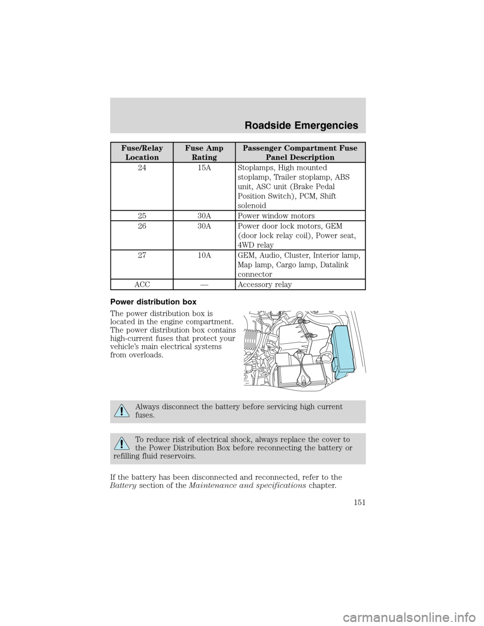
Fuse/Relay
LocationFuse Amp
RatingPassenger Compartment Fuse
Panel Description
24 15A Stoplamps, High mounted
stoplamp, Trailer stoplamp, ABS
unit, ASC unit (Brake Pedal
Position Switch), PCM, Shift
solenoid
25 30A Power window motors
26 30A Power door lock motors, GEM
(door lock relay coil), Power seat,
4WD relay
27 10A GEM, Audio, Cluster, Interior lamp,
Map lamp, Cargo lamp, Datalink
connector
ACC—Accessory relay
Power distribution box
The power distribution box is
located in the engine compartment.
The power distribution box contains
high-current fuses that protect your
vehicle’s main electrical systems
from overloads.
Always disconnect the battery before servicing high current
fuses.
To reduce risk of electrical shock, always replace the cover to
the Power Distribution Box before reconnecting the battery or
refilling fluid reservoirs.
If the battery has been disconnected and reconnected, refer to the
Batterysection of theMaintenance and specificationschapter.
Roadside Emergencies
151
Page 154 of 240

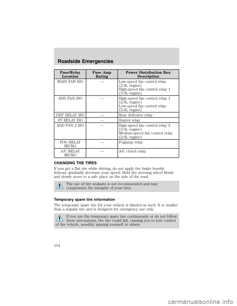
Fuse/Relay
LocationFuse Amp
RatingPower Distribution Box
Description
MAIN FAN ISO—Low-speed fan control relay
(2.0L engine)
High-speed fan control relay 1
(3.0L engine)
ADD FAN ISO—High-speed fan control relay 1
(2.0L engine)
Low-speed fan control relay
(3.0L engine)
DEF RELAY ISO—Rear defroster relay
ST RELAY ISO—Starter relay
ADD FAN 2 ISO—High-speed fan control relay 2
(3.0L engine)
Medium-speed fan control relay
(2.0L engine)
FOG RELAY
MICRO—Foglamp relay
A/C RELAY
MICRO—A/C clutch relay
CHANGING THE TIRES
If you get a flat tire while driving, do not apply the brake heavily.
Instead, gradually decrease your speed. Hold the steering wheel firmly
and slowly move to a safe place on the side of the road.
The use of tire sealants is not recommended and may
compromise the integrity of your tires.
Temporary spare tire information
The temporary spare tire for your vehicle is labeled as such. It is smaller
than a regular tire and is designed for emergency use only.
If you use the temporary spare tire continuously or do not follow
these precautions, the tire could fail, causing you to lose control
of the vehicle, possibly injuring yourself or others.
Roadside Emergencies
154
Page 156 of 240
1. Park on a level surface, activate
hazard flashers and place gearshift
lever in P (Park) (automatic
transmission) or R (Reverse)
(manual transmission).
2. Set the parking brake and turn
engine OFF.
3. Block the diagonally opposite
wheel.
4. Lift the cargo cover and remove
the tool bag with jack handle, lug
nut wrench and long spare tire rod
and spare tire from the wheel well.
5. Loosen each wheel lug nut
one-half turn counterclockwise but
do not remove them until the wheel
is raised off the ground.
Roadside Emergencies
156
Page 158 of 240
Never use the differentials as a
jacking point.
To lessen the risk of
personal injury, do not put
any part of your body under the
vehicle while changing a tire. Do
not start the engine when your
vehicle is on the jack. The jack is
only meant for changing the tire.
7. Remove the lug nuts with the lug nut wrench.
8. Replace the flat tire with the spare tire, making sure the valve stem is
facing outward. Reinstall lug nuts until the wheel is snug against the hub.
Do not fully tighten the lug nuts until the wheel has been lowered.
9. Lower the wheel by turning the jack handle counterclockwise.
10. Remove the jack and fully
tighten the lug nuts in the order
shown.
1
4 3
2 5
Roadside Emergencies
158
Page 160 of 240

Preparing your vehicle
When the battery is disconnected or a new battery is installed, the
transmission must relearn its shift strategy. As a result, the transmission
may have firm and/or soft shifts. This operation is considered normal and
will not affect function or durability of the transmission. Over time, the
adaptive learning process will fully update transmission operation.
1.Use only a 12–volt supply to start your vehicle.
2. Do not disconnect the battery of the disabled vehicle as this could
damage the vehicle’s electrical system.
3. Park the booster vehicle close to the hood of the disabled vehicle
making sure the two vehiclesdo nottouch. Set the parking brake on
both vehicles and stay clear of the engine cooling fan and other moving
parts.
4. Check all battery terminals and remove any excessive corrosion before
you attach the battery cables. Ensure that vent caps are tight and level.
5. Turn the heater fan on in both vehicles to protect any electrical
surges. Turn all other accessories off.
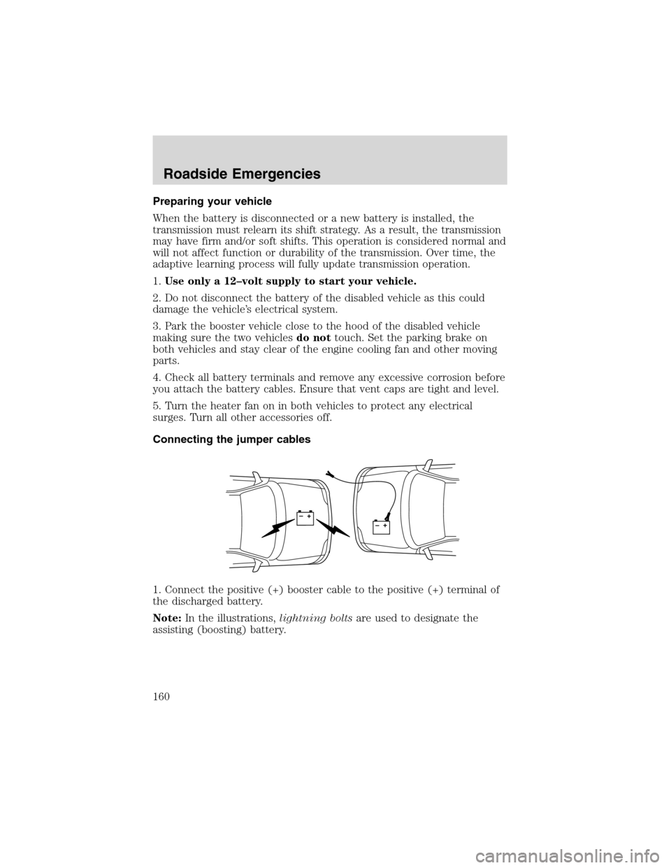
Connecting the jumper cables
1. Connect the positive (+) booster cable to the positive (+) terminal of
the discharged battery.
Note:In the illustrations,lightning boltsare used to designate the
assisting (boosting) battery.
+–+–
Roadside Emergencies
160
Page 162 of 240
4. Make the final connection of the negative (-) cable to an exposed
metal part of the stalled vehicle’s engine, away from the battery and the
carburetor/fuel injection system.Do notuse fuel lines, engine rocker
covers or the intake manifold asgroundingpoints.
Do not connect the end of the second cable to the negative (-)
terminal of the battery to be jumped. A spark may cause an
explosion of the gases that surround the battery.
5. Ensure that the cables are clear of fan blades, belts, moving parts of
both engines, or any fuel delivery system parts.
Jump starting
1. Start the engine of the booster vehicle and run the engine at
moderately increased speed.
2. Start the engine of the disabled vehicle.
3. Once the disabled vehicle has been started, run both engines for an
additional three minutes before disconnecting the jumper cables.
+–+–
Roadside Emergencies
162
Page 164 of 240
3. Remove the jumper cable from the positive (+) terminal of the booster
vehicle’s battery.
4. Remove the jumper cable from the positive (+) terminal of the
disabled vehicle’s battery.
After the disabled vehicle has been started and the jumper cables
removed, allow it to idle for several minutes so the engine computer can
relearnits idle conditions.
+–+–
+–+–
Roadside Emergencies
164
Page 173 of 240

UTILIZING THE MEDIATION/ARBITRATION PROGRAM
(CANADA ONLY)
In those cases where you continue to feel that the efforts by Ford and
the dealer to resolve a factory-related vehicle service concern have been
unsatisfactory, Ford of Canada participates in an impartial third party
mediation/arbitration program administered by the Canadian Motor
Vehicle Arbitration Plan (CAMVAP).
The CAMVAP program is a straight-forward and relatively speedy
alternative to resolve a disagreement when all other efforts to produce a
settlement have failed. This procedure is without cost to you and is
designed to eliminate the need for lengthy and expensive legal
proceedings.
In the CAMVAP program, impartial third-party arbitrators conduct
hearings at mutually convenient times and places in an informal
environment. These impartial arbitrators review the positions of the
parties, make decisions and, when appropriate, render awards to resolve
disputes. CAMVAP decisions are fast, fair, and final; the arbitrator’s
award is binding both to you and Ford of Canada.
CAMVAP services are available in all territories and provinces. For more
information, without charge or obligation, call your CAMVAP Provincial
Administrator directly at 1-800-207-0685.
GETTING ASSISTANCE OUTSIDE THE U.S. AND CANADA
Before exporting your vehicle to a foreign country, contact the
appropriate foreign embassy or consulate. These officials can inform you
of local vehicle registration regulations and where to find unleaded fuel.
If you cannot find unleaded fuel or can only get fuel with an anti-knock
index lower than is recommended for your vehicle, contact a district or
owner relations/customer relationship office.
The use of leaded fuel in your vehicle without proper conversion may
damage the effectiveness of your emission control system and may cause
engine knocking or serious engine damage. Ford Motor Company/Ford of
Canada is not responsible for any damage caused by use of improper
fuel.
In the United States, using leaded fuel may also result in difficulty
importing your vehicle back into the U.S.
Customer Assistance
173