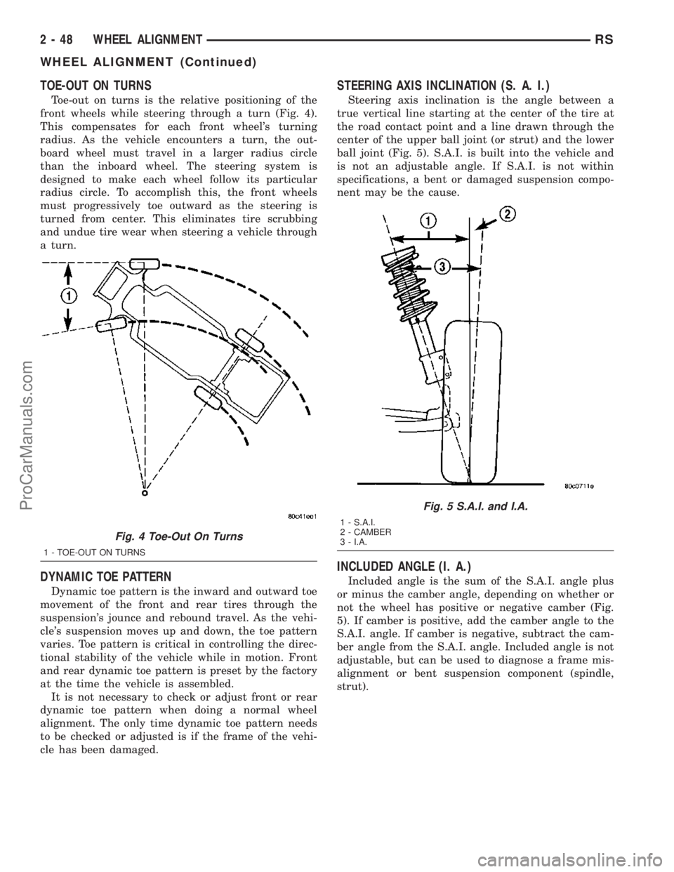
2003 DODGE TOWN AND COUNTRY factory reset
[x] Cancel search: factory resetPage 91 of 2177

TOE-OUT ON TURNS
Toe-out on turns is the relative positioning of the
front wheels while steering through a turn (Fig. 4).
This compensates for each front wheel's turning
radius. As the vehicle encounters a turn, the out-
board wheel must travel in a larger radius circle
than the inboard wheel. The steering system is
designed to make each wheel follow its particular
radius circle. To accomplish this, the front wheels
must progressively toe outward as the steering is
turned from center. This eliminates tire scrubbing
and undue tire wear when steering a vehicle through
a turn.
DYNAMIC TOE PATTERN
Dynamic toe pattern is the inward and outward toe
movement of the front and rear tires through the
suspension's jounce and rebound travel. As the vehi-
cle's suspension moves up and down, the toe pattern
varies. Toe pattern is critical in controlling the direc-
tional stability of the vehicle while in motion. Front
and rear dynamic toe pattern is preset by the factory
at the time the vehicle is assembled.
It is not necessary to check or adjust front or rear
dynamic toe pattern when doing a normal wheel
alignment. The only time dynamic toe pattern needs
to be checked or adjusted is if the frame of the vehi-
cle has been damaged.
STEERING AXIS INCLINATION (S. A. I.)
Steering axis inclination is the angle between a
true vertical line starting at the center of the tire at
the road contact point and a line drawn through the
center of the upper ball joint (or strut) and the lower
ball joint (Fig. 5). S.A.I. is built into the vehicle and
is not an adjustable angle. If S.A.I. is not within
specifications, a bent or damaged suspension compo-
nent may be the cause.
INCLUDED ANGLE (I. A.)
Included angle is the sum of the S.A.I. angle plus
or minus the camber angle, depending on whether or
not the wheel has positive or negative camber (Fig.
5). If camber is positive, add the camber angle to the
S.A.I. angle. If camber is negative, subtract the cam-
ber angle from the S.A.I. angle. Included angle is not
adjustable, but can be used to diagnose a frame mis-
alignment or bent suspension component (spindle,
strut).
Fig. 4 Toe-Out On Turns
1 - TOE-OUT ON TURNS
Fig. 5 S.A.I. and I.A.
1 - S.A.I.
2 - CAMBER
3 - I.A.
2 - 48 WHEEL ALIGNMENTRS
WHEEL ALIGNMENT (Continued)
ProCarManuals.com
Page 307 of 2177

grid can be repaired using a Mopar Rear Window
Defogger Repair Kit (Part Number 4267922) or
equivalent. (Refer to 8 - ELECTRICAL/HEATED
GLASS/WINDSHIELD GRID - STANDARD PROCE-
DURE).
RADIO
DESCRIPTION
Available factory-installed radio receivers for this
model include:
²AM/FM/cassette/CD (RAZ sales code)
²AM/FM/CD with CD changer control (RBK sales
code)
²AM/FM/cassette with CD changer control fea-
ture (RBB sales code)
²AM/FM/cassette/CD with rear audio (RBU sales
code)
All factory-installed radio receivers can communi-
cate on the Programmable Communications Interface
(PCI) data bus network. All factory-installed receiv-
ers are stereo Electronically Tuned Radios (ETR) and
include an electronic digital clock function.
These radio receivers can only be serviced by an
authorized radio repair station. See the latest War-
ranty Policies and Procedures manual for a current
listing of authorized radio repair stations.
OPERATION
The radio receiver operates on ignition switched
battery current that is available only when the igni-
tion switch is in the On or Accessory/Accessory Delay
positions. The electronic digital clock function of the
radio operates on fused battery current supplied
through the IOD fuse, regardless of the ignition
switch position.
For more information on the features, setting pro-
cedures, and control functions for each of the avail-
able factory-installed radio receivers, refer to the
owner's manual. For complete circuit diagrams, refer
to the appropriate wiring information. The wiring
information includes wiring diagrams, proper wire
and connector repair procedures, details of wire har-
ness routing and retention, connector pin-out infor-
mation and location views for the various wire
harness connectors, splices and grounds.
DIAGNOSIS AND TESTING - RADIO
WARNING: ON VEHICLES EQUIPPED WITH AIR-
BAGS, REFER TO ELECTRICAL, RESTRAINTS
BEFORE ATTEMPTING ANY STEERING WHEEL,
STEERING COLUMN, OR INSTRUMENT PANEL
COMPONENT DIAGNOSIS OR SERVICE. FAILURE
TO TAKE THE PROPER PRECAUTIONS COULDRESULT IN ACCIDENTAL AIRBAG DEPLOYMENT
AND POSSIBLE PERSONAL INJURY.
Any diagnosis of the Audio system should
begin with the use of the DRB IIItdiagnostic
tool. For information on the use of the DRB
IIIt, refer to the appropriate Diagnostic Service
Manual.
Refer to the appropriate wiring information. The
wiring information includes wiring diagrams, proper
wire and connector repair procedures, details of wire
harness routing and retention, connector pin-out
information and location views for the various wire
harness connectors, splices and grounds.
If the vehicle is equipped with remote radio
switches located on the back of the steering wheel
spokes, and the problem being diagnosed is related to
one of the symptoms listed below, be certain to check
the remote radio switches and circuits as described
in this group, prior to attempting radio diagnosis or
repair.
²Stations changing with no remote radio switch
input
²Radio memory presets not working properly
²Volume changes with no remote radio switch
input
²Remote radio switch buttons taking on other
functions
²CD player skipping tracks
²Remote radio switch inoperative.
CAUTION: The speaker output of the radio is a
ªfloating groundº system. Do not allow any speaker
lead to short to ground, as damage to the radio
may result.
(1) Check the fuse(s) in the junction block and the
Integrated Power Module (IPM). If OK, go to Step 2.
If not OK, repair the shorted circuit or component as
required and replace the faulty fuse(s).
(2) Check for battery voltage at the fuse in the
(IPM). If OK, go to Step 3. If not OK, repair the open
circuit to the battery as required.
(3) Turn the ignition switch to the ON position.
Check for battery voltage at the fuse in the junction
block. If OK, go to Step 4. If not OK, repair the open
circuit to the ignition switch as required.
(4) Turn the ignition switch to the OFF position.
Remove the radio, but do not unplug the wire har-
ness connectors. Check for continuity between the
radio chassis and a good ground. There should be
continuity. If OK, go to Step 5. If not OK, repair the
open radio chassis ground circuit as required.
(5) Connect the battery negative cable. Turn the
ignition switch to the ON position. Check for battery
voltage at the fused ignition switch output circuit
cavity of the radio wire harness connector. If OK, go
8A - 10 AUDIORS
QUARTER GLASS INTEGRAL ANTENNA - EXPORT (Continued)
ProCarManuals.com
Page 451 of 2177

PROGRAMMABLE FEATURES
NOTE: Tire pressure monitoring (TPM) system infor-
mation is not covered in this section of the service
manual. Refer to the tires/wheels section of this
manual for detailed tire pressure monitoring system
information.
²LANGUAGE?- The options include English,
Francaise, Deutsch, Italiana, or Espanol. The default
is English. All EVIC display nomenclature, including
the trip computer functions, warning messages and
the programmable features appear in the selected
language.
²DISPLAY U.S. OR METRIC?- The options
include U.S. and M. The default is U.S. This feature
toggles the trip computer temperature, fuel economy
and odometer display readings between U.S. and
metric units of measure. It also changes the odome-
ter display in the instrument cluster.
²SERVICE INTV. =- The options include from
1000 to 12000 kilometers in 1000 kilometer incre-
ments (2000 to 7500 miles in 500 mile increments).
The default is 12000 kilometers (7500 miles). The
selected distance becomes the interval at which the
Perform Service warning message will be displayed
by the EVIC. If a new distance is selected, a second
programmable feature appears,RESET SERVICE
DISTANCE?- The options include No and Yes. The
default is Yes. When Yes is selected, the accumulated
distance since the last previous Perform Service
warning message will be reset to zero because the
service interval has been changed. When No is
selected, the distance until the next Perform Service
warning message is reduced by the accumulated dis-
tance since the last previous message.
²USE FACTORY SETTINGS?- The options
include Yes and No. The default is Yes. When yes is
selected all the programmable features will return to
there defaults and the rest of the programmable fea-
tures will not be displayed. If No is selected the rest
of the programmable features will be displayed at
there default values. This feature will automatically
return to the Yes default under two conditions. First,
if no programmable features are changed from there
defaults. Second, if all the programmable features
equal there defaults.
²AUTO DOOR LOCKS?- The options include
Yes and No. The default is Yes. When Yes is selected,
all doors and the liftgate lock automatically when
vehicle speed reaches 25 kilometers-per-hour (15
miles-per-hour). If YES is selected, a second program-
mable feature appears,AUTO UNLOCK ON EXIT?
- The options again include Yes and No. The default
is No. When Yes is selected, following each Auto Door
Lock event all doors and the liftgate will automati-
cally unlock when the driver door is opened, if thevehicle is stopped and the transmission gear selector
is in Park or Neutral. The Auto Door Unlock event
will only occur once following each Auto Door Lock
event.
²REMOTE UNLOCK- The options include
Driver Door 1st and All Doors. The default is Driver
Door 1st. When Diver Door 1st is selected, only the
driver door unlocks when the Unlock button of the
Remote Keyless Entry (RKE) transmitter is
depressed once. The Unlock button of the RKE trans-
mitter must be depressed twice to unlock all doors.
When All Doors is selected, all doors unlock when the
Unlock button of the RKE transmitter is depressed
once.
²REMOTE LINKED TO MEMORY?- This pro-
grammable feature only applies to vehicles equipped
with the optional memory / heated system. The
options include Yes and No. The default is No. When
Yes is selected, the memory system will recall the
Driver 1 or Driver 2 memory settings assigned to the
RKE transmitter being used to unlock the vehicle.
When No is selected, the memory system will only
recall memory settings when the Driver 1 or Driver 2
push buttons of the memory switch on the driver side
front door trim panel are depressed.
²SOUND HORN ON LOCK?- The options
include Yes and No. The default is No. When Yes is
selected, a short horn chirp will provide an audible
confirmation when the RKE receiver recognizes a
valid Lock signal from an RKE transmitter. When No
is selected, no horn chirp will occur with the RKE
Lock event. This feature may be selected indepen-
dent of theFLASH LIGHTS WITH LOCKS?pro-
grammable feature.
²FLASH LIGHTS WITH LOCKS?- The options
include Yes and No. The default is Yes. When Yes is
selected, a single flash of the hazard warning lamps
will provide an optical confirmation when the RKE
receiver recognizes a valid Lock signal from an RKE
transmitter, and two flashes of the same lamps will
occur when the RKE receiver recognizes a valid
Unlock signal from an RKE transmitter. When No is
selected, no lamp flash will occur with the RKE Lock
or Unlock event. This feature may be selected inde-
pendent of theSOUND HORN ON LOCK?pro-
grammable feature.
²HEADLAMP DELAY =- The options include
Off, 30 Sec, 60 Sec, and 90 Sec. The default is 90 Sec.
When a time interval is selected, the headlamps will
remain on for that length of time when the head-
lamps are turned off after the ignition is turned off,
or if the Auto mode is selected on vehicles with the
Auto Headlamps option. When Off is selected, the
headlamp delay feature is disabled.
²HEADLAMPS ON WITH WIPERS?- This pro-
grammable feature only applies to vehicles equipped
8M - 8 MESSAGE SYSTEMSRS
ELECTRONIC VEHICLE INFO CENTER (Continued)
ProCarManuals.com
Page 506 of 2177

The power seat system includes the following com-
ponents:
²Power seat recliners
²Power seat switches
²Power seat tracks
²Circuit breaker
The power seat system with memory and heated
seat options includes the following components:
²Power seat recliner
²Power seat switch
²Power seat track.
²Memory Seat Mirror Module (MSMM)
²Memory set switch
²Heated Seat Module (HSM)
²Heated seat switch
²Electronic Vehicle Information Center (EVIC)
²Programmable Communications Interface (PCI)
data bus network
Refer to Wiring Diagrams for complete circuit dia-
grams. Following are general descriptions and opera-
tions for the major components in the power seat
system and memory seat system.
DESCRIPTION - MEMORY SYSTEM
An electronic memory system is available on some
models. The memory system is able to store and
recall the driver side power seat positions (including
the power recliner position) and both outside side
view mirrors positions for two drivers. On vehicles
equipped with a factory radio, the memory system is
also able to store and recall radio station presets fortwo drivers. The memory system also will store and
recall the last station listened to for each driver, even
if it is not one of the preset stations.
The memory system will automatically return to
its preset settings when the corresponding numbered
button of the memory switch is depressed, or when
the doors are unlocked using the corresponding
Remote Keyless Entry (RKE) transmitter. A customer
programmable feature of the memory system allows
the RKE recall of memory features to be disabled, if
desired. This programmable feature is internal in the
EVIC module, which is located in the overhead con-
sole.
A Memory Seat Mirror Module (MSMM) is used on
some models to control and integrate the many elec-
tronic functions and features included in the memory
seat and mirror systems.
The memory system includes the following compo-
nents:
²Memory Seat Mirror Module (MSMM)
²Memory set switch
²Position potentiometers on both outside side
view mirrors
²Position potentiometers on the driver side power
seat track and power seat recliner motors.
²Electronic Vehicle Information Center (EVIC)
²Radio receiver (if PCI data bus capable).
Certain functions of the memory system rely upon
resources shared with other electronic modules in the
vehicle over the Programmable Communications
Interface (PCI) J1850 data bus network. The PCI
data bus network allows the sharing of sensor infor-
mation. This helps to reduce wire harness complexity,
internal controller hardware, and component sensor
current loads. At the same time, this system provides
increased reliability, enhanced diagnostics, and
allows the addition of many new feature capabilities.
Initial diagnosis of these electronic modules or the
PCI data bus network requires the use of a DRBIIIt
scan tool and the proper Diagnostic Procedures man-
ual. If this method does not prove conclusive, the use
of a automotive meter such as the Fluket, the proper
wiring schematics and the service manual diagnostic
routines are required.
The other electronic modules that may affect mem-
ory system operation are as follows:
²Body Control Module (BCM)- Refer toBody
Control Modulein Electronic Control Modules for
more information.
²Powertrain Control Module (PCM)- Refer to
Powertrain Control Modulein Electronic Control
Modules for more information.
²Transmission Control Module (TCM)- Refer
toTransmission Control Modulein Electronic
Control Modules for more information.
Fig. 1 Identifying a Side Airbag Equipped Seat
1 - Airbag Label
RSPOWER SEAT SYSTEM8N-51
POWER SEAT SYSTEM (Continued)
ProCarManuals.com