Page 659 of 1184

5B–34 FIVE-SPEED MANUAL TRANSAXLE
DAEWOO M-150 BL2
D13B737A
15. Install the counter shaft fifth gear nut.
�Shift the shift yoke using a screwdriver to engage
the first–gear and the third–gear or the second–
gear and the fourth–gear (1).
Tighten
Tighten the fifth gear nut to 60–80 N�m (44–59 lb-ft).
�Caulk the nut using a chisel and a hammer (2).
D103B710
16. Install the input shaft fifth gear bearing and the fifth
gear / synchronizer ring.
�Insert the bearing into the input shaft.
�Install the fifth gear, wave spring and synchroniz-
er ring matching synchronizer’s oil groove and in-
put shaft punched mark (1).
D103B738
17. Install the fifth gear synchronizer hub assembly.
�Install the synchronizer springs to hub (1).
�Install the synchronizer key (2).
Important: In case of assembling synchronizer sleeve
and hub, let A=B.
�Position the longer boss side of hub toward inner
side (3).
�Position the chamfered spline of sleeve toward
inner side and install the hub to the sleeve (4).
D103B739
18. Install the fifth gear fork to the synchronizer hub as-
sembly.
19. Install the fifth gear fork and the synchronizer hub
assembly to the input shaft.
Important: Position the longer boss side of hub toward
inner side and match the synchronizer key and the hub
groove with the input shaft punched mark.
Page 663 of 1184
.
�Remove the synchronizer sleeve and the key (2).
�Rem")
5B–38 FIVE-SPEED MANUAL TRANSAXLE
DAEWOO M-150 BL2
D103B751
8. Disassemble the third–fourth synchronizer hub as-
sembly.
�Remove the hub (1).
�Remove the synchronizer sleeve and the key (2).
�Remove the synchronizer springs (3).
D103B752
9. Remove the input shaft third gear bearing (1).
D103B753
Synchronizer Assembly Inspection
1. Inspecting wear of cone area.
�After matching synchronizer ring to gear, measure
as shown in figure. Replace if it is below limit.
Unit : mm (in.)
������� �������Clearance Between������ ������Standard������ ������Limit������� �������Clearance Between
Gear and Ring
1.0 (0.039)0.5 (0.020)
D103B754
2. Inspecting cone contact condition.
�When synchronizer mechanism is abnormal in op-
eration, connection between ring inner surface and
gear cone area is considered to be partially defec-
tive in spite of correct clearance between gear and
ring. Therefore, cone area and ring inner surface
shall be inspected. In this case, ring inner surface
shall be glossy. Black area is abnormal and if in-
spection is difficult, check after applying red lead.
Cone area can be worn in wave form.
Page 664 of 1184
FIVE-SPEED MANUAL TRANSAXLE 5B–39
DAEWOO M-150 BL2
D103B755
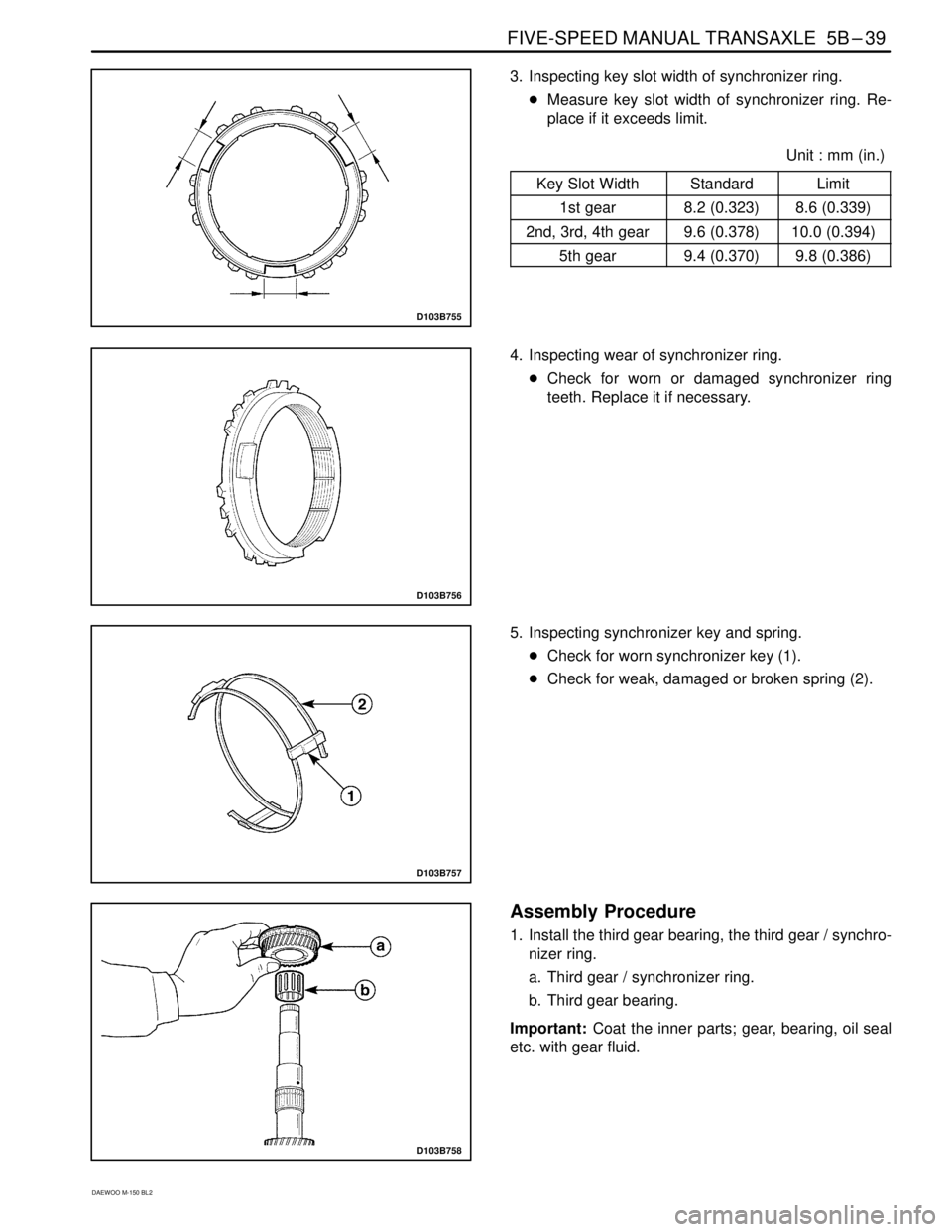
3. Inspecting key slot width of synchronizer ring.
�Measure key slot width of synchronizer ring. Re-
place if it exceeds limit.
�����������������Unit : mm (in.)
������� �������Key Slot Width������ ������Standard������ ������Limit
������� �������1st gear8.2 (0.323)8.6 (0.339)
������� �������2nd, 3rd, 4th gear9.6 (0.378)10.0 (0.394)
������� �������5th gear9.4 (0.370)9.8 (0.386)
D103B756
4. Inspecting wear of synchronizer ring.
�Check for worn or damaged synchronizer ring
teeth. Replace it if necessary.
D103B757
5. Inspecting synchronizer key and spring.
�Check for worn synchronizer key (1).
�Check for weak, damaged or broken spring (2).
D103B758
Assembly Procedure
1. Install the third gear bearing, the third gear / synchro-
nizer ring.
a. Third gear / synchronizer ring.
b. Third gear bearing.
Important: Coat the inner parts; gear, bearing, oil seal
etc. with gear fluid.
Page 665 of 1184

5B–40 FIVE-SPEED MANUAL TRANSAXLE
DAEWOO M-150 BL2
D103B759
2. Assemble the third–fourth synchronizer hub assem-
bly.
�Install the synchronizer springs to the hub.
�Install the synchronizer key to the hub.
Important: In case of assembling the synchronizer
sleeve and the hub, let A=B.
�Install the hub to the sleeve.
a. Sleeve.
b. Hub.
D103B760
3. Install the third–fourth synchronizer hub assembly.
�Insert the hub assembly into the input shaft (1).
Important: Position the longer flange of hub toward the
third gear and match the key and the ring groove.
�Install the hub assembly using a hammer and the
gear, bearing installer DW09940–53111.
D13B761A
Notice: When installing gear, bearing and hub assem-
bly, install them slowly using the gear, bearing installer
DW09940–53111 and a hammer. If overpressed, the
gear teeth may be damaged.
D103B749
4. Install the third–fourth synchronizer circlip.
5. Install the fourth synchronizer ring and wave spring.
Important: Match the ring groove to the key of hub.
Page 668 of 1184
FIVE-SPEED MANUAL TRANSAXLE 5B–43
DAEWOO M-150 BL2
D103B769
9. Remove the counter shaft first–second gear syn-
chronizer hub assembly, the first gear / the first gear
synchronizer ring.
�Position the first gear to the gear, bearing remov-
er DW09921–57810.
�Remove the following parts by pressing.
a. Synchronizer hub assembly.
b. First gear / First gear synchronizer ring.
�Remove the first gear synchronizer ring from the
first gear.
D103B770
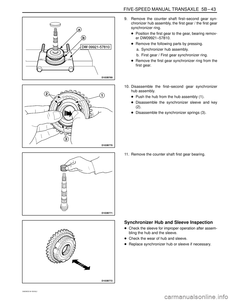
10. Disassemble the first–second gear synchronizer
hub assembly.
�Push the hub from the hub assembly (1).
�Disassemble the synchronizer sleeve and key
(2).
�Disassemble the synchronizer springs (3).
D103B771
11. Remove the counter shaft first gear bearing.
D103B772
Synchronizer Hub and Sleeve Inspection
�Check the sleeve for improper operation after assem-
bling the hub and the sleeve.
�Check the wear of hub and sleeve.
�Replace synchronizer hub or sleeve if necessary.
Page 669 of 1184
.
�Install the first gear (2).
�In")
5B–44 FIVE-SPEED MANUAL TRANSAXLE
DAEWOO M-150 BL2
D103B773
Assembly Procedure
1. Install the related counter shaft first gear.
�Install the first gear bearing (1).
�Install the first gear (2).
�Install the first gear synchronizer ring (3)
Important: Coat the inner parts; gear, bearing and oil
seal etc. with gear fluid.
Important: Be careful there is the difference of key
groove width between the first synchronizer ring and the
second synchronizer ring.
D103B774A
Unit : mm (in.)
��������� �
��������
��������� �
��������
First synchronizer ring (A)
: 8.2 (0.323)
��������� �
�������� ���������
Key Groove Width��������� �
�������� ���������Second synchronizer ring
(B) : 9.6 (0.378)
D103B775
2. Assemble the first–second synchronizer hub assem-
bly.
�Install the synchronizer springs to hub.
�Install the synchronizer keys to hub.
Important: Let (A)=(B) when installing the keys.
�Install the hub to the sleeve.
a. Sleeve.
b. Hub.
D103B776
3. Install the first–second synchronizer hub assembly.
�Insert the hub assembly into the counter shaft us-
ing the gear, bearing installer DW09940–53111,
the gear bearing remover/installer KM466–A and a
hammer (1).
Important: Position the synchronizer key to the first
gear synchronizer ring groove.
Page 670 of 1184
FIVE-SPEED MANUAL TRANSAXLE 5B–45
DAEWOO M-150 BL2
D103B768
4. Install the second synchronizer ring.
Important: Position the second synchronizer ring groove
to the synchronizer hub key.
5. Install the first–second gear synchronizer circlip.
D103B777
6. Install the related counter shaft second gear.
�Install the second gear bearing (1).
�Install the second gear (2).
D103B778
7. Install the counter shaft third gear and the third–fourth
gear spacer.
�Insert the third gear and the third–fourth gear
spacer into the counter shaft.
�Install the following parts using the gear, bearing
installer DW09913–80112 and a hammer.
a. Third–fourth gear spacer.
b. Third gear.
D103B779
8. Install the counter shaft fourth gear.
�Install the fourth gear to the counter shaft using the
gear, bearing installer DW09925–98221 and a
hammer (1).
Page 677 of 1184

5B–52 FIVE-SPEED MANUAL TRANSAXLE
DAEWOO M-150 BL2
SPECIFICATIONS
GENERAL SPECIFICATIONS
ApplicationDescriptionUnitStandardLimit
GeneralTypeForward gear–Synchronized
mesh type–
Reverse gear–Sliding mesh
type–
Gear ratio1st–3.818–
2nd–2.210–
3rd–1.423–
4th–1.029–
5th–0.837–
Reverse–3.583–
Final drive ratio–4.444–
Fluid capacityL(qt)2.1 (2.21)–
Fluid classification–75W-85 (GL-4)–
ServiceKey groove width of1st gearmm(in.)8.2 (0.323)8.6 (0.339)
synchronizer ring2nd, 3rd, 4th gearmm(in.)9.6 (0.378)10.0 (0.394)
5th gearmm(in.)9.4 (0.370)9.8 (0.386)
Shift fork end
thicknessLow speed shift fork
(1st~2nd)mm(in.)8.7 (0.343)8.1 (0.319)
High speed shift fork
(3rd~4th)mm(in.)7.8 (0.307)7.2 (0.283)
5th gear shift forkmm(in.)7.8 (0.307)7.2 (0.283)
Clearance between gear and synchronizer
ringmm(in.)1.0 (0.039)0.5 (0.020)
Clearance between sleeve and shift forkmm(in.)0.2 – 0.6
(0.008 – 0.024)1.0 (0.039)
Thrust free play of differential side gearmm(in.)0.05 – 0.33
(0.002 – 0.013)–
Speedometer gear ratio(Driven/Drive)–17/18 (0.944)–