2003 CHRYSLER VOYAGER fuel pressure
[x] Cancel search: fuel pressurePage 1696 of 2177
Since there are four switches, there are 16 possible
combinations of open and closed switches (codes).
Seven of these codes are related to gear position and
three are recognized as ªbetween gearº codes. This
results in six codes which should never occur. These
are called ªinvalidº codes. An invalid code will result
in a DTC, and the PCM/TCM will then determine the
shift lever position based on pressure switch data.
This allows reasonably normal transmission opera-
tion with a TRS failure.
TRS SWITCH STATES
SLP T42 T41 T3 T1
PCL CL CL OP
RCL OP OP OP
NCL CL OP CL
ODOP OP OP CL
3OP OP CL OP
LCL OP CL CL
TRANSMISSION TEMPERATURE SENSOR
The TRS has an integrated thermistor (Fig. 329)
that the PCM/TCM uses to monitor the transmis-
sion's sump temperature. Since fluid temperature
can affect transmission shift quality and convertor
lock up, the PCM/TCM requires this information to
determine which shift schedule to operate in. The
PCM also monitors this temperature data so it can
energize the vehicle cooling fan(s) when a transmis-
sion ªoverheatº condition exists. If the thermistor cir-
cuit fails, the PCM/TCM will revert to calculated oil
temperature usage.
CALCULATED TEMPERATURE
A failure in the temperature sensor or circuit will
result in calculated temperature being substituted for
actual temperature. Calculated temperature is a pre-
dicted fluid temperature which is calculated from a
combination of inputs:
²Battery (ambient) temperature
²Engine coolant temperature
²In-gear run time since start-up
REMOVAL
(1) Remove valve body assembly from transaxle.
(Refer to 21 - TRANSMISSION/TRANSAXLE/AUTO-
MATIC - 41TE/VALVE BODY - REMOVAL)
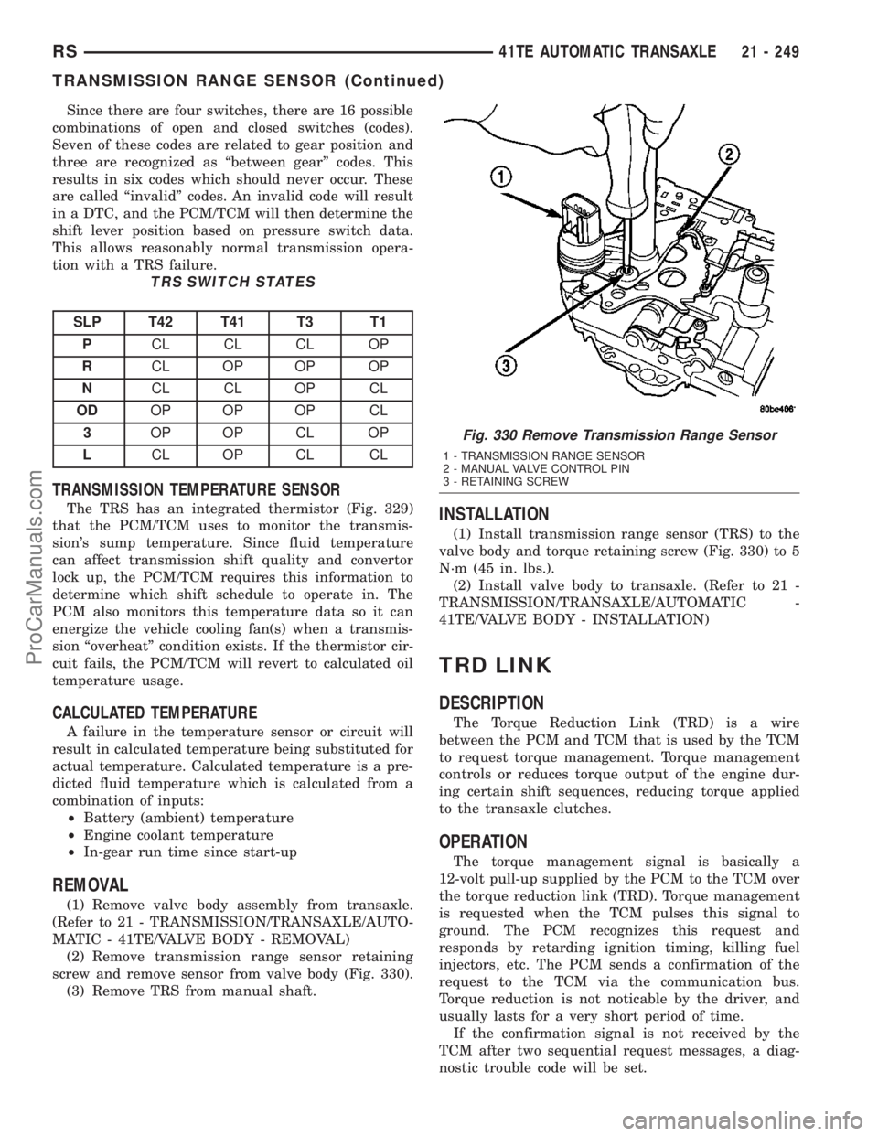
(2) Remove transmission range sensor retaining
screw and remove sensor from valve body (Fig. 330).
(3) Remove TRS from manual shaft.
INSTALLATION
(1) Install transmission range sensor (TRS) to the
valve body and torque retaining screw (Fig. 330) to 5
N´m (45 in. lbs.).
(2) Install valve body to transaxle. (Refer to 21 -
TRANSMISSION/TRANSAXLE/AUTOMATIC -
41TE/VALVE BODY - INSTALLATION)
TRD LINK
DESCRIPTION
The Torque Reduction Link (TRD) is a wire
between the PCM and TCM that is used by the TCM
to request torque management. Torque management
controls or reduces torque output of the engine dur-
ing certain shift sequences, reducing torque applied
to the transaxle clutches.
OPERATION
The torque management signal is basically a
12-volt pull-up supplied by the PCM to the TCM over
the torque reduction link (TRD). Torque management
is requested when the TCM pulses this signal to
ground. The PCM recognizes this request and
responds by retarding ignition timing, killing fuel
injectors, etc. The PCM sends a confirmation of the
request to the TCM via the communication bus.
Torque reduction is not noticable by the driver, and
usually lasts for a very short period of time.
If the confirmation signal is not received by the
TCM after two sequential request messages, a diag-
nostic trouble code will be set.
Fig. 330 Remove Transmission Range Sensor
1 - TRANSMISSION RANGE SENSOR
2 - MANUAL VALVE CONTROL PIN
3 - RETAINING SCREW
RS41TE AUTOMATIC TRANSAXLE21 - 249
TRANSMISSION RANGE SENSOR (Continued)
ProCarManuals.com
Page 1728 of 2177
pressures may increase from 2 to 6 pounds per
square inch (psi) (14 to 41 kPa) during operation. Do
not reduce this normal pressure buildup.
Improper inflation can cause:
²Uneven wear patterns
²Reduced tread life
²Reduced fuel economy
²Unsatisfactory ride
²The vehicle to drift.
WARNING: OVER OR UNDER INFLATED TIRES CAN
AFFECT VEHICLE HANDLING. THE TIRE CAN FAIL
SUDDENLY, RESULTING IN LOSS OF VEHICLE
CONTROL.
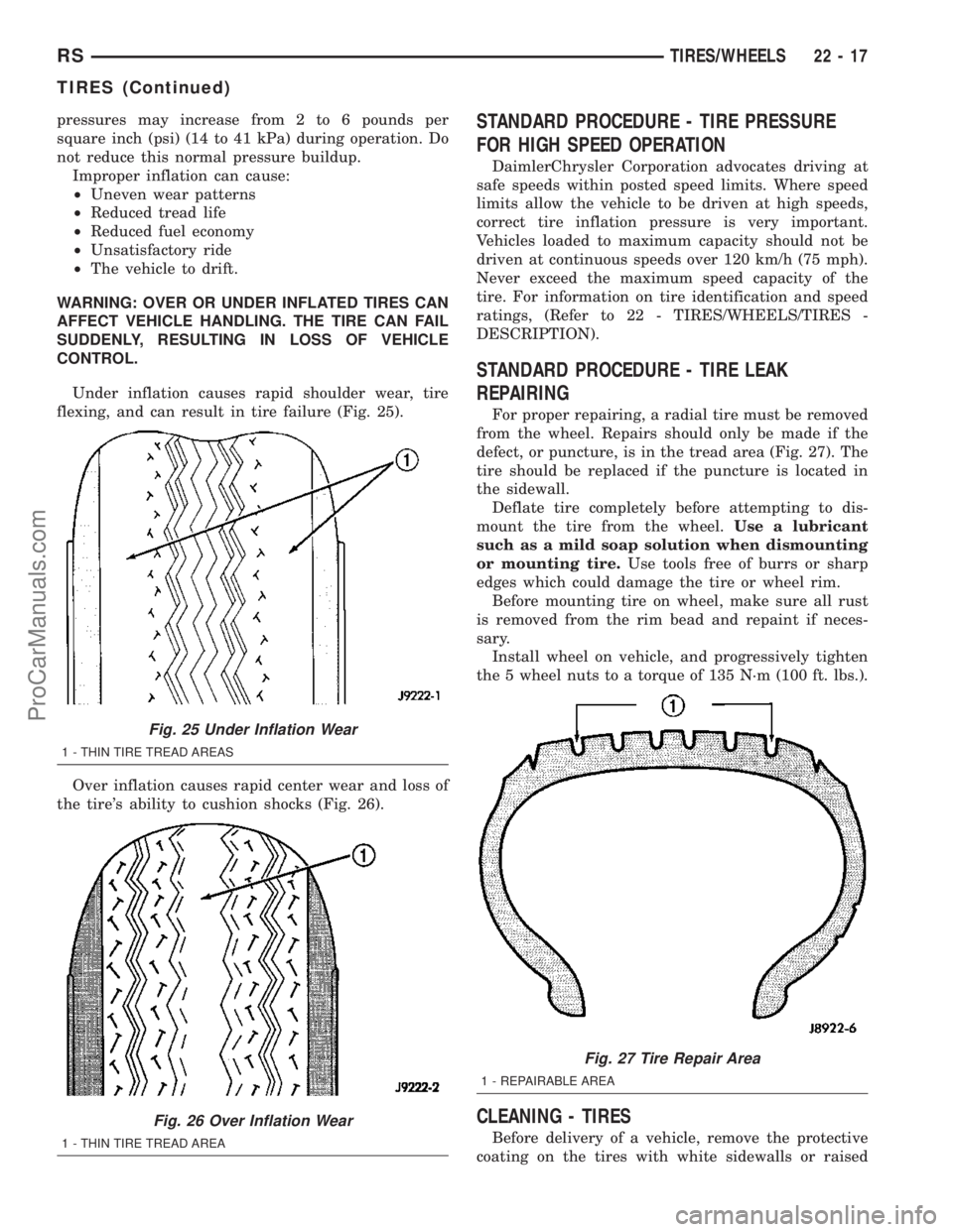
Under inflation causes rapid shoulder wear, tire
flexing, and can result in tire failure (Fig. 25).
Over inflation causes rapid center wear and loss of
the tire's ability to cushion shocks (Fig. 26).STANDARD PROCEDURE - TIRE PRESSURE
FOR HIGH SPEED OPERATION
DaimlerChrysler Corporation advocates driving at
safe speeds within posted speed limits. Where speed
limits allow the vehicle to be driven at high speeds,
correct tire inflation pressure is very important.
Vehicles loaded to maximum capacity should not be
driven at continuous speeds over 120 km/h (75 mph).
Never exceed the maximum speed capacity of the
tire. For information on tire identification and speed
ratings, (Refer to 22 - TIRES/WHEELS/TIRES -
DESCRIPTION).
STANDARD PROCEDURE - TIRE LEAK
REPAIRING
For proper repairing, a radial tire must be removed
from the wheel. Repairs should only be made if the
defect, or puncture, is in the tread area (Fig. 27). The
tire should be replaced if the puncture is located in
the sidewall.
Deflate tire completely before attempting to dis-
mount the tire from the wheel.Use a lubricant
such as a mild soap solution when dismounting
or mounting tire.Use tools free of burrs or sharp
edges which could damage the tire or wheel rim.
Before mounting tire on wheel, make sure all rust
is removed from the rim bead and repaint if neces-
sary.
Install wheel on vehicle, and progressively tighten
the 5 wheel nuts to a torque of 135 N´m (100 ft. lbs.).
CLEANING - TIRES
Before delivery of a vehicle, remove the protective
coating on the tires with white sidewalls or raised
Fig. 25 Under Inflation Wear
1 - THIN TIRE TREAD AREAS
Fig. 26 Over Inflation Wear
1 - THIN TIRE TREAD AREA
Fig. 27 Tire Repair Area
1 - REPAIRABLE AREA
RSTIRES/WHEELS22-17
TIRES (Continued)
ProCarManuals.com
Page 2106 of 2177
CONDITIONING/CABIN HEATER/FUEL LINE -
INSTALLATION).
(4) Connect the electrical connector to the fuel
pump by depressing the integral spring and pushing
the connector towards the dosing pump. Pull the con-
nector towards the heater to verify the installation.
(5) Verify function of the heater.
FUEL LINE
STANDARD PROCEDURE - CLEANING
(1) Remove the cabin heater fuel line(Refer to 24 -
HEATING & AIR CONDITIONING/CABIN HEAT-
ER/FUEL LINE - REMOVAL).
(2) With cabin heater line removed from vehicle
place a shop cloth on the fuel tank end of the fuel
line to catch any residue, then apply a small amount
of air pressure to the other end of the fuel line.
(3) Check to see if air pressure is coming from the
tank end of the line. If pressure is flowing unre-
stricted the line is clean.
(4) If the line shows any signs of being restricted
after air pressure is applied, then the fuel line should
be replaced.(5) Install the cabin heater line(Refer to 24 -
HEATING & AIR CONDITIONING/CABIN HEAT-
ER/FUEL LINE - INSTALLATION).
(6) Verify function of the heater.
REMOVAL
(1) Elevate vehicle on a lift taking note of the
heater exhaust tube flexible section.
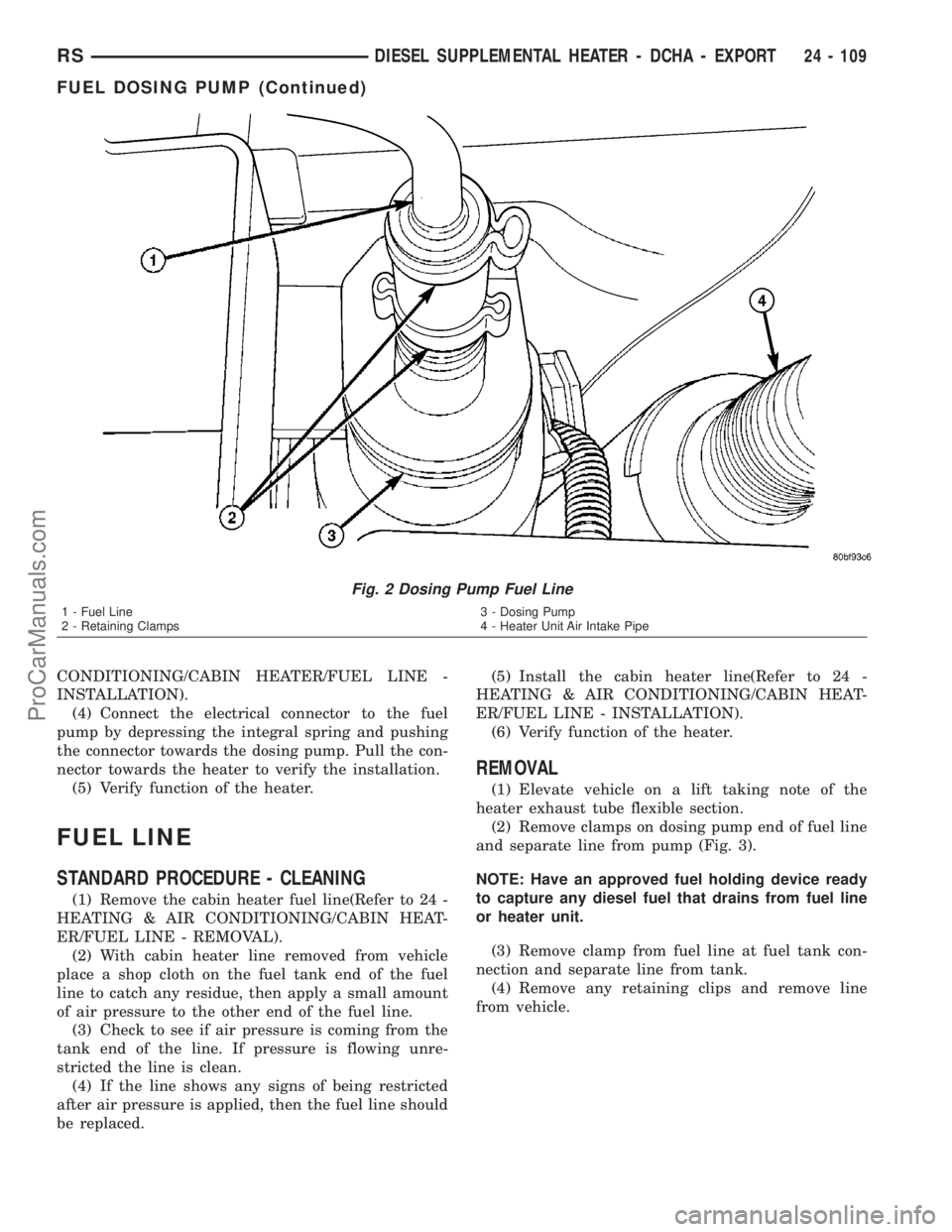
(2) Remove clamps on dosing pump end of fuel line
and separate line from pump (Fig. 3).
NOTE: Have an approved fuel holding device ready
to capture any diesel fuel that drains from fuel line
or heater unit.
(3) Remove clamp from fuel line at fuel tank con-
nection and separate line from tank.
(4) Remove any retaining clips and remove line
from vehicle.
Fig. 2 Dosing Pump Fuel Line
1 - Fuel Line
2 - Retaining Clamps3 - Dosing Pump
4 - Heater Unit Air Intake Pipe
RSDIESEL SUPPLEMENTAL HEATER - DCHA - EXPORT24 - 109
FUEL DOSING PUMP (Continued)
ProCarManuals.com
Page 2113 of 2177
The following is a list of the monitored compo-
nents:
²Comprehensive Components
²Oxygen Sensor Monitor
²Oxygen Sensor Heater Monitor
²Catalyst Monitor
COMPREHENSIVE COMPONENTS
Along with the major monitors, OBD II requires
that the diagnostic system monitor any component
that could affect emissions levels. In many cases,
these components were being tested under OBD I.
The OBD I requirements focused mainly on testing
emissions-related components for electrical opens and
shorts.
However, OBD II also requires that inputs from
powertrain components to the PCM be tested for
rationality, and that outputs to powertrain compo-
nents from the PCM be tested forfunctionality.
Methods for monitoring the various Comprehensive
Component monitoring include:
(1) Circuit Continuity
²Open
²Shorted high
²Shorted to ground
(2) Rationality or Proper Functioning
²Inputs tested for rationality
²Outputs tested for functionality
NOTE: Comprehensive component monitors are
continuous. Therefore, enabling conditions do not
apply.
Input RationalityÐWhile input signals to the
PCM are constantly being monitored for electrical
opens and shorts, they are also tested for rationality.
This means that the input signal is compared against
other inputs and information to see if it makes sense
under the current conditions.
PCM sensor inputs that are checked for rationality
include:
²Manifold Absolute Pressure (MAP) Sensor
²Oxygen Sensor (O2S)
²Engine Coolant Temperature (ECT) Sensor
²Camshaft Position (CMP) Sensor
²Vehicle Speed Sensor
²Crankshaft Position (CKP) Sensor
²Intake/inlet Air Temperature (IAT) Sensor
²Throttle Position (TPS) Sensor
²Ambient Temperature Sensors
²Power Steering Switch
²Oxygen Sensor Heater
²Brake Switch
²Leak Detection Pump Switch or NVLD switch (if
equipped)
²P/N SwitchOutput FunctionalityÐPCM outputs are tested
for functionality in addition to testing for opens and
shorts. When the PCM provides a voltage to an out-
put component, it can verify that the command was
carried out by monitoring specific input signals for
expected changes. For example, when the PCM com-
mands the Idle Air Control (IAC) Motor to a specific
position under certain operating conditions, it expects
to see a specific (target) idle speed (RPM). If it does
not, it stores a DTC.
PCM outputs monitored for functionality include:
²Fuel Injectors
²Ignition Coils
²Idle Air Control
²Purge Solenoid
²EGR Solenoid (if equipped)
²LDP Solenoid or NVLD solenoid (if equipped)
²Radiator Fan Control
²Trans Controls
OXYGEN SENSOR (O2S) MONITOR
DESCRIPTIONÐEffective control of exhaust
emissions is achieved by an oxygen feedback system.
The most important element of the feedback system
is the O2S. The O2S is located in the exhaust path.
Once it reaches operating temperature 300É to 350ÉC
(572É to 662ÉF), the sensor generates a voltage that
is inversely proportional to the amount of oxygen in
the exhaust. When there is a large amount of oxygen
in the exhaust caused by a lean condition, the sensor
produces a low voltage, below 450 mV. When the oxy-
gen content is lower, caused by a rich condition, the
sensor produces a higher voltage, above 450mV (volt-
ages are offset by 2.5 volts on NGC vehicles).
The information obtained by the sensor is used to
calculate the fuel injector pulse width. The PCM is
programmed to maintain the optimum air/fuel ratio.
At this mixture ratio, the catalyst works best to
remove hydrocarbons (HC), carbon monoxide (CO)
and nitrous oxide (NOx) from the exhaust.
The O2S is also the main sensing element for the
EGR (if equipped), Catalyst and Fuel Monitors.
The O2S may fail in any or all of the following
manners:
²Slow response rate (Big Slope)
²Reduced output voltage (Half Cycle)
²Heater Performance
Slow Response Rate (Big Slope)ÐResponse rate
is the time required for the sensor to switch from
lean to rich signal output once it is exposed to a
richer than optimum A/F mixture or vice versa. As
the PCM adjusts the air/fuel ratio, the sensor must
be able to rapidly detect the change. As the sensor
ages, it could take longer to detect the changes in the
oxygen content of the exhaust gas. The rate of
change that an oxygen sensor experiences is called
25 - 2 EMISSIONS CONTROLRS
EMISSIONS CONTROL (Continued)
ProCarManuals.com
Page 2114 of 2177

ªBig Slopeº. The PCM checks the oxygen sensor volt-
age in increments of a few milliseconds.
Reduced Output Voltage (Half Cycle)ÐThe
output voltage of the O2S ranges from 0 to 1 volt
(voltages are offset by 2.5 volts on NGC vehicles). A
good sensor can easily generate any output voltage in
this range as it is exposed to different concentrations
of oxygen. To detect a shift in the A/F mixture (lean
or rich), the output voltage has to change beyond a
threshold value. A malfunctioning sensor could have
difficulty changing beyond the threshold value. Each
time the voltage signal surpasses the threshold, a
counter is incremented by one. This is called the Half
Cycle Counter.
Heater PerformanceÐThe heater is tested by a
separate monitor. Refer to the Oxygen Sensor Heater
Monitor.
OPERATIONÐAs the Oxygen Sensor signal
switches, the PCM monitors the half cycle and big
slope signals from the oxygen sensor. If during the
test neither counter reaches a predetermined value, a
malfunction is entered and Freeze Frame data is
stored. Only one counter reaching its predetermined
value is needed for the monitor to pass.
The Oxygen Sensor Monitor is a two trip monitor
that is tested only once per trip. When the Oxygen
Sensor fails the test in two consecutive trips, the
MIL is illuminated and a DTC is set. The MIL is
extinguished when the Oxygen Sensor monitor
passes in three consecutive trips. The DTC is erased
from memory after 40 consecutive warm-up cycles
without test failure.
Enabling ConditionsÐThe following conditions
must typically be met for the PCM to run the oxygen
sensor monitor:
²Battery voltage
²Engine temperature
²Engine run time
²Engine run time at a predetermined speed
²Engine run time at a predetermined speed and
throttle opening
²Transmission in gear and brake depressed (auto-
matic only)
²Fuel system in Closed Loop
²Long Term Adaptive (within parameters)
²Power Steering Switch in low PSI (no load)
²Engine at idle
²Fuel level above 15%
²Ambient air temperature
²Barometric pressure
²Engine RPM within acceptable range of desired
idle
Pending ConditionsÐThe Task Manager typi-
cally does not run the Oxygen Sensor Monitor if over-
lapping monitors are running or the MIL is
illuminated for any of the following:²Misfire Monitor
²Front Oxygen Sensor and Heater Monitor
²MAP Sensor
²Vehicle Speed Sensor
²Engine Coolant Temperature Sensor
²Throttle Position Sensor
²Engine Controller Self Test Faults
²Cam or Crank Sensor
²Injector and Coil
²Idle Air Control Motor
²EVAP Electrical
²EGR Solenoid Electrical (if equipped)
²Intake/inlet Air Temperature
²5 Volt Feed
ConflictÐThe Task Manager does not run the
Oxygen Sensor Monitor if any of the following condi-
tions are present:
²A/C ON (A/C clutch cycling temporarily sus-
pends monitor)
²Purge flow in progress
²Ethanol content learn is taking place and the
ethanol used once flag is set (if equipped)
SuspendÐThe Task Manager suspends maturing
a fault for the Oxygen Sensor Monitor if any of the
following are present:
²Oxygen Sensor Heater Monitor, Priority 1
²Misfire Monitor, Priority 2
OXYGEN SENSOR HEATER MONITOR
DESCRIPTIONÐIf there is an oxygen sensor
(O2S) DTC as well as a O2S heater DTC, the O2S
fault MUST be repaired first. After the O2S fault is
repaired, verify that the heater circuit is operating
correctly.
The voltage readings taken from the O2S are very
temperature sensitive. The readings are not accurate
below a sensor temperature of 300ÉC. Heating of the
O2S is done to allow the engine controller to shift to
closed loop control as soon as possible. The heating
element used to heat the O2S must be tested to
ensure that it is heating the sensor properly.
The heater element itself is not tested. The sensor
output is used to test the heater by isolating the
effect of the heater element on the O2S output volt-
age from the other effects. The resistance is normally
between 100 ohms and 4.5 megaohms. When oxygen
sensor temperature increases, the resistance in the
internal circuit decreases. The PCM sends a 5 volts
biased signal through the oxygen sensors to ground
this monitoring circuit. As the temperature increases,
resistance decreases and the PCM detects a lower
voltage at the reference signal. Inversely, as the tem-
perature decreases, the resistance increases and the
PCM detects a higher voltage at the reference signal.
The O2S circuit is monitored for a drop in voltage.
RSEMISSIONS CONTROL25-3
EMISSIONS CONTROL (Continued)
ProCarManuals.com
Page 2116 of 2177
period the switch ratio reaches a predetermined
value, a counter is incremented by one. The monitor
is enabled to run another test during that trip. When
the test fails 6 times, the counter increments to 3, a
malfunction is entered, and a Freeze Frame is stored,
the code is matured and the MIL is illuminated. If
the first test passes, no further testing is conducted
during that trip.
The MIL is extinguished after three consecutive
good trips. The good trip criteria for the catalyst
monitor is more stringent than the failure criteria. In
order to pass the test and increment one good trip,
the downstream sensor switch rate must be less than
45% of the upstream rate. The failure percentages
are 59% respectively.
Enabling ConditionsÐThe following conditions
must typically be met before the PCM runs the cat-
alyst monitor. Specific times for each parameter may
be different from engine to engine.
²Accumulated drive time
²Enable time
²Ambient air temperature
²Barometric pressure
²Catalyst warm-up counter
²Engine coolant temperature
²Vehicle speed
²MAP
²RPM
²Engine in closed loop
²Fuel level
Pending ConditionsÐ
²Misfire DTC
²Front Oxygen Sensor Response
²Front Oxygen Sensor Heater Monitor
²Front Oxygen Sensor Electrical
²Rear Oxygen Sensor Rationality (middle check)
²Rear Oxygen Sensor Heater Monitor
²Rear Oxygen Sensor Electrical
²Fuel System Monitor
²All TPS faults
²All MAP faults
²All ECT sensor faults
²Purge flow solenoid functionality
²Purge flow solenoid electrical
²All PCM self test faults
²All CMP and CKP sensor faults
²All injector and ignition electrical faults
²Idle Air Control (IAC) motor functionality
²Vehicle Speed Sensor
²Brake switch (auto trans only)
²Intake air temperature
ConflictÐThe catalyst monitor does not run if any
of the following are conditions are present:
²EGR Monitor in progress (if equipped)
²Fuel system rich intrusive test in progress
²EVAP Monitor in progress²Time since start is less than 60 seconds
²Low fuel level-less than 15 %
²Low ambient air temperature
²Ethanol content learn is taking place and the
ethanol used once flag is set
SuspendÐThe Task Manager does not mature a
catalyst fault if any of the following are present:
²Oxygen Sensor Monitor, Priority 1
²Oxygen Sensor Heater, Priority 1
²EGR Monitor, Priority 1 (if equipped)
²EVAP Monitor, Priority 1
²Fuel System Monitor, Priority 2
²Misfire Monitor, Priority 2
OPERATION - NON-MONITORED CIRCUITS
The PCM does not monitor all circuits, systems
and conditions that could have malfunctions causing
driveability problems. However, problems with these
systems may cause the PCM to store diagnostic trou-
ble codes for other systems or components. For exam-
ple, a fuel pressure problem will not register a fault
directly, but could cause a rich/lean condition or mis-
fire. This could cause the PCM to store an oxygen
sensor or misfire diagnostic trouble code.
The major non-monitored circuits are listed below
along with examples of failures modes that do not
directly cause the PCM to set a DTC, but for a sys-
tem that is monitored.
FUEL PRESSURE
The fuel pressure regulator controls fuel system
pressure. The PCM cannot detect a clogged fuel
pump inlet filter, clogged in-line fuel filter, or a
pinched fuel supply or return line. However, these
could result in a rich or lean condition causing the
PCM to store an oxygen sensor, fuel system, or mis-
fire diagnostic trouble code.
SECONDARY IGNITION CIRCUIT
The PCM cannot detect an inoperative ignition coil,
fouled or worn spark plugs, ignition cross firing, or
open spark plug cables. The misfire will however,
increase the oxygen content in the exhaust, deceiving
the PCM in to thinking the fuel system is too lean.
Also see misfire detection.
CYLINDER COMPRESSION
The PCM cannot detect uneven, low, or high engine
cylinder compression. Low compression lowers O2
content in the exhaust. Leading to fuel system, oxy-
gen sensor, or misfire detection fault.
EXHAUST SYSTEM
The PCM cannot detect a plugged, restricted or
leaking exhaust system. It may set a EGR (if
equipped) or Fuel system or O2S fault.
RSEMISSIONS CONTROL25-5
EMISSIONS CONTROL (Continued)
ProCarManuals.com
Page 2119 of 2177
chemical reaction takes place. This means the con-
centration of oxygen will be the same downstream as
upstream. The output voltage of the downstream
O2S copies the voltage of the upstream sensor. The
only difference is a time lag (seen by the PCM)
between the switching of the O2S's.
To monitor the system, the number of lean-to-rich
switches of upstream and downstream O2S's is
counted. The ratio of downstream switches to
upstream switches is used to determine whether the
catalyst is operating properly. An effective catalyst
will have fewer downstream switches than it has
upstream switches i.e., a ratio closer to zero. For a
totally ineffective catalyst, this ratio will be one-to-
one, indicating that no oxidation occurs in the device.
The system must be monitored so that when cata-
lyst efficiency deteriorates and exhaust emissions
increase to over the legal limit, the MIL (Check
Engine lamp) will be illuminated.
NATURAL VACUUM LEAK DETECTION (NVLD) (if equipped)
The Natural Vacuum Leak Detection (NVLD) sys-
tem is the next generation evaporative leak detection
system that will first be used on vehicles equipped
with the Next Generation Controller (NGC). This
new system replaces the leak detection pump as the
method of evaporative system leak detection. This is
to detect a leak equivalent to a 0.0209(0.5 mm) hole.
This system has the capability to detect holes of this
size very dependably.
The basic leak detection theory employed with
NVLD is the9Gas Law9. This is to say that the pres-
sure in a sealed vessel will change if the temperature
of the gas in the vessel changes. The vessel will only
see this effect if it is indeed sealed. Even small leaks
will allow the pressure in the vessel to come to equi-
librium with the ambient pressure. In addition to the
detection of very small leaks, this system has the
capability of detecting medium as well as large evap-
orative system leaks.
The NVLD seals the canister vent during engine off
conditions. If the EVAP system has a leak of less than
the failure threshold, the evaporative system will be
pulled into a vacuum, either due to the cool down
from operating temperature or diurnal ambient tem-
perature cycling. The diurnal effect is considered one
of the primary contributors to the leak determination
by this diagnostic. When the vacuum in the system
exceeds about 19H2O (0.25 KPA), a vacuum switch
closes. The switch closure sends a signal to the NGC.
The NGC, via appropriate logic strategies (described
below), utilizes the switch signal, or lack thereof, to
make a determination of whether a leak is present.
The NVLD device is designed with a normally open
vacuum switch, a normally closed solenoid, and a
seal, which is actuated by both the solenoid and a
diaphragm. The NVLD is located on the atmosphericvent side of the canister. The NVLD assembly may
be mounted on top of the canister outlet, or in-line
between the canister and atmospheric vent filter. The
normally open vacuum switch will close with about 19
H2O (0.25 KPA) vacuum in the evaporative system.
The diaphragm actuates the switch. This is above the
opening point of the fuel inlet check valve in the fill
tube so cap off leaks can be detected. Submerged fill
systems must have recirculation lines that do not
have the in-line normally closed check valve that pro-
tects the system from failed nozzle liquid ingestion,
in order to detect cap off conditions.
The normally closed valve in the NVLD is intended
to maintain the seal on the evaporative system dur-
ing the engine off condition. If vacuum in the evapo-
rative system exceeds 39to 69H2O (0.75 to 1.5 KPA),
the valve will be pulled off the seat, opening the seal.
This will protect the system from excessive vacuum
as well as allowing sufficient purge flow in the event
that the solenoid was to become inoperative.
The solenoid actuates the valve to unseal the can-
ister vent while the engine is running. It also will be
used to close the vent during the medium and large
leak tests and during the purge flow check. This sole-
noid requires initial 1.5 amps of current to pull the
valve open but after 100 ms. will be duty cycled down
to an average of about 150 mA for the remainder of
the drive cycle.
Another feature in the device is a diaphragm that
will open the seal in the NVLD with pressure in the
evaporative system. The device will9blow off9at
about 0.59H2O (0.12 KPA) pressure to permit the
venting of vapors during refueling. An added benefit
to this is that it will also allow the tank to9breathe9
during increasing temperatures, thus limiting the
pressure in the tank to this low level. This is benefi-
cial because the induced vacuum during a subse-
quent declining temperature will achieve the switch
closed (pass threshold) sooner than if the tank had to
decay from a built up pressure.
The device itself has 3 wires: Switch sense, sole-
noid driver and ground. It also includes a resistor to
protect the switch from a short to battery or a short
to ground. The NGC utilizes a high-side driver to
energize and duty-cycle the solenoid.
DESCRIPTION - HIGH AND LOW LIMITS
The PCM compares input signal voltages from each
input device with established high and low limits for
the device. If the input voltage is not within limits
and other criteria are met, the PCM stores a diagnos-
tic trouble code in memory. Other diagnostic trouble
code criteria might include engine RPM limits or
input voltages from other sensors or switches that
must be present before verifying a diagnostic trouble
code condition.
25 - 8 EMISSIONS CONTROLRS
EMISSIONS CONTROL (Continued)
ProCarManuals.com
Page 2122 of 2177
SPECIFICATIONS
TORQUE
DESCRIPTION N´m Ft. Lbs. In. Lbs.
PCV VAlve 3.3/3.8L 6.3 55
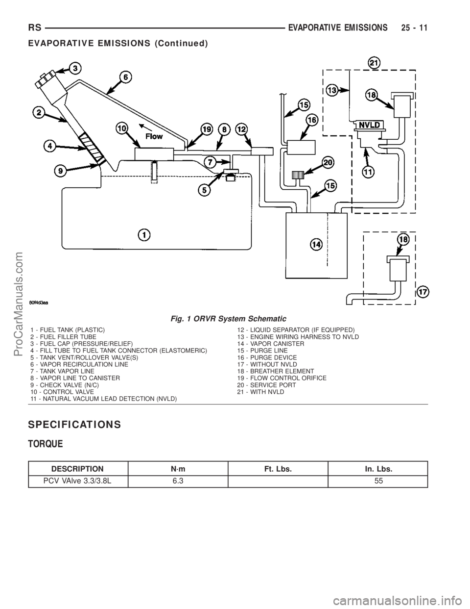
Fig. 1 ORVR System Schematic
1 - FUEL TANK (PLASTIC)
2 - FUEL FILLER TUBE
3 - FUEL CAP (PRESSURE/RELIEF)
4 - FILL TUBE TO FUEL TANK CONNECTOR (ELASTOMERIC)
5 - TANK VENT/ROLLOVER VALVE(S)
6 - VAPOR RECIRCULATION LINE
7 - TANK VAPOR LINE
8 - VAPOR LINE TO CANISTER
9 - CHECK VALVE (N/C)
10 - CONTROL VALVE
11 - NATURAL VACUUM LEAD DETECTION (NVLD)12 - LIQUID SEPARATOR (IF EQUIPPED)
13 - ENGINE WIRING HARNESS TO NVLD
14 - VAPOR CANISTER
15 - PURGE LINE
16 - PURGE DEVICE
17 - WITHOUT NVLD
18 - BREATHER ELEMENT
19 - FLOW CONTROL ORIFICE
20 - SERVICE PORT
21 - WITH NVLD
RSEVAPORATIVE EMISSIONS25-11
EVAPORATIVE EMISSIONS (Continued)
ProCarManuals.com