2003 CHRYSLER VOYAGER airbag
[x] Cancel search: airbagPage 1108 of 2177
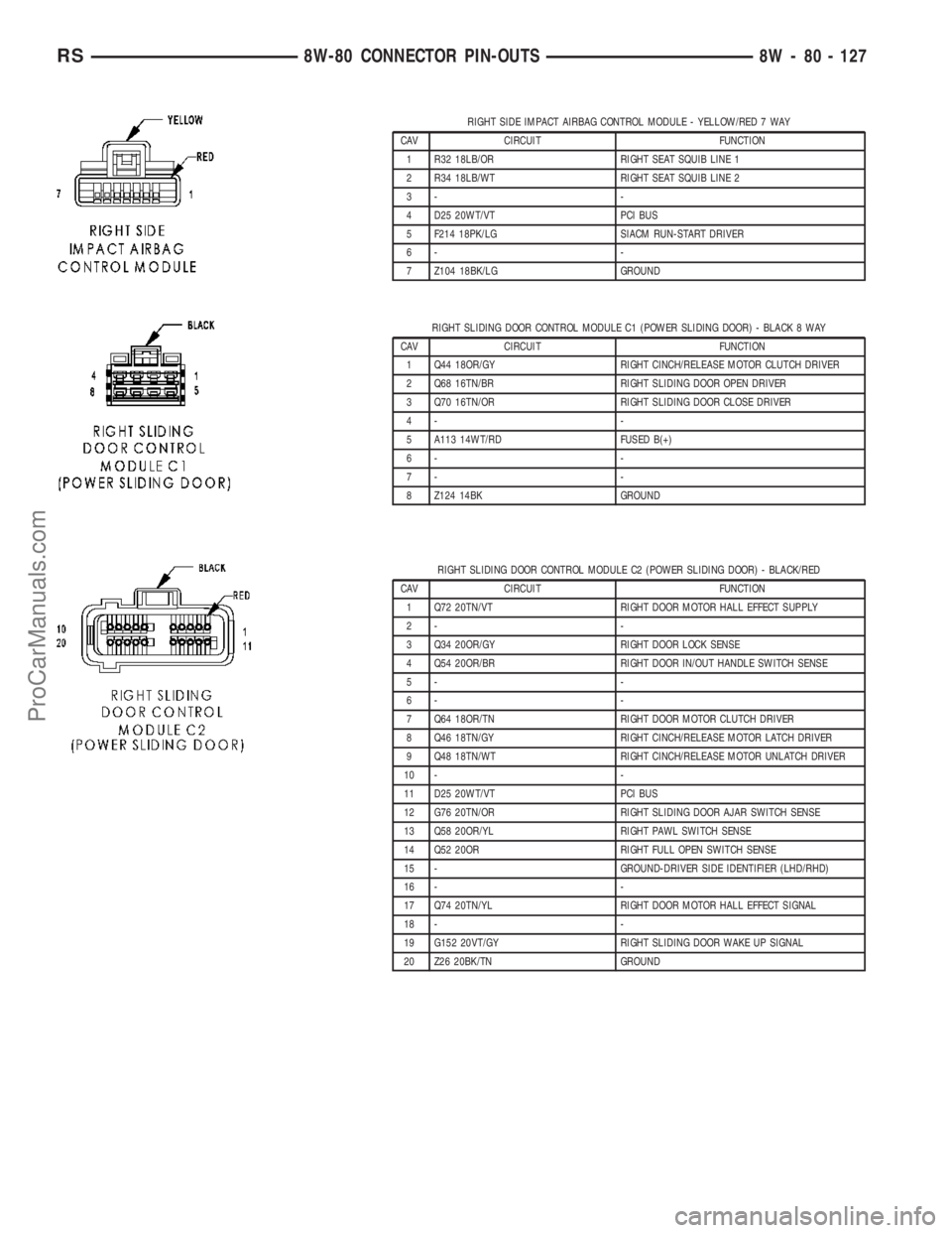
RIGHT SIDE IMPACT AIRBAG CONTROL MODULE - YELLOW/RED 7 WAY
CAV CIRCUIT FUNCTION
1 R32 18LB/OR RIGHT SEAT SQUIB LINE 1
2 R34 18LB/WT RIGHT SEAT SQUIB LINE 2
3- -
4 D25 20WT/VT PCI BUS
5 F214 18PK/LG SIACM RUN-START DRIVER
6- -
7 Z104 18BK/LG GROUND
RIGHT SLIDING DOOR CONTROL MODULE C1 (POWER SLIDING DOOR) - BLACK 8 WAY
CAV CIRCUIT FUNCTION
1 Q44 18OR/GY RIGHT CINCH/RELEASE MOTOR CLUTCH DRIVER
2 Q68 16TN/BR RIGHT SLIDING DOOR OPEN DRIVER
3 Q70 16TN/OR RIGHT SLIDING DOOR CLOSE DRIVER
4- -
5 A113 14WT/RD FUSED B(+)
6- -
7- -
8 Z124 14BK GROUND
RIGHT SLIDING DOOR CONTROL MODULE C2 (POWER SLIDING DOOR) - BLACK/RED
CAV CIRCUIT FUNCTION
1 Q72 20TN/VT RIGHT DOOR MOTOR HALL EFFECT SUPPLY
2- -
3 Q34 20OR/GY RIGHT DOOR LOCK SENSE
4 Q54 20OR/BR RIGHT DOOR IN/OUT HANDLE SWITCH SENSE
5- -
6- -
7 Q64 18OR/TN RIGHT DOOR MOTOR CLUTCH DRIVER
8 Q46 18TN/GY RIGHT CINCH/RELEASE MOTOR LATCH DRIVER
9 Q48 18TN/WT RIGHT CINCH/RELEASE MOTOR UNLATCH DRIVER
10 - -
11 D25 20WT/VT PCI BUS
12 G76 20TN/OR RIGHT SLIDING DOOR AJAR SWITCH SENSE
13 Q58 20OR/YL RIGHT PAWL SWITCH SENSE
14 Q52 20OR RIGHT FULL OPEN SWITCH SENSE
15 - GROUND-DRIVER SIDE IDENTIFIER (LHD/RHD)
16 - -
17 Q74 20TN/YL RIGHT DOOR MOTOR HALL EFFECT SIGNAL
18 - -
19 G152 20VT/GY RIGHT SLIDING DOOR WAKE UP SIGNAL
20 Z26 20BK/TN GROUND
RS8W-80 CONNECTOR PIN-OUTS8W - 80 - 127
ProCarManuals.com
Page 1116 of 2177
8W-91 CONNECTOR/GROUND/SPLICE LOCATION
TABLE OF CONTENTS
page
CONNECTOR/GROUND/SPLICE LOCATION
DESCRIPTION..........................1
CONNECTOR/GROUND/SPLICE
LOCATION
DESCRIPTION
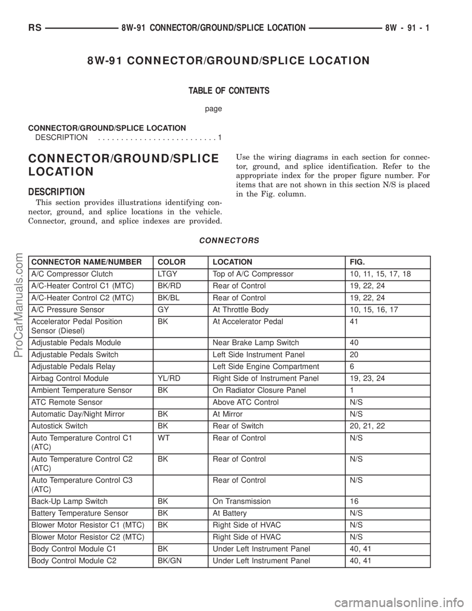
This section provides illustrations identifying con-
nector, ground, and splice locations in the vehicle.
Connector, ground, and splice indexes are provided.Use the wiring diagrams in each section for connec-
tor, ground, and splice identification. Refer to the
appropriate index for the proper figure number. For
items that are not shown in this section N/S is placed
in the Fig. column.
CONNECTORS
CONNECTOR NAME/NUMBER COLOR LOCATION FIG.
A/C Compressor Clutch LTGY Top of A/C Compressor 10, 11, 15, 17, 18
A/C-Heater Control C1 (MTC) BK/RD Rear of Control 19, 22, 24
A/C-Heater Control C2 (MTC) BK/BL Rear of Control 19, 22, 24
A/C Pressure Sensor GY At Throttle Body 10, 15, 16, 17
Accelerator Pedal Position
Sensor (Diesel)BK At Accelerator Pedal 41
Adjustable Pedals Module Near Brake Lamp Switch 40
Adjustable Pedals Switch Left Side Instrument Panel 20
Adjustable Pedals Relay Left Side Engine Compartment 6
Airbag Control Module YL/RD Right Side of Instrument Panel 19, 23, 24
Ambient Temperature Sensor BK On Radiator Closure Panel 1
ATC Remote Sensor Above ATC Control N/S
Automatic Day/Night Mirror BK At Mirror N/S
Autostick Switch BK Rear of Switch 20, 21, 22
Auto Temperature Control C1
(ATC)WT Rear of Control N/S
Auto Temperature Control C2
(ATC)BK Rear of Control N/S
Auto Temperature Control C3
(ATC)Rear of Control N/S
Back-Up Lamp Switch BK On Transmission 16
Battery Temperature Sensor BK At Battery N/S
Blower Motor Resistor C1 (MTC) BK Right Side of HVAC N/S
Blower Motor Resistor C2 (MTC) Right Side of HVAC N/S
Body Control Module C1 BK Under Left Instrument Panel 40, 41
Body Control Module C2 BK/GN Under Left Instrument Panel 40, 41
RS8W-91 CONNECTOR/GROUND/SPLICE LOCATION8W-91-1
ProCarManuals.com
Page 1118 of 2177
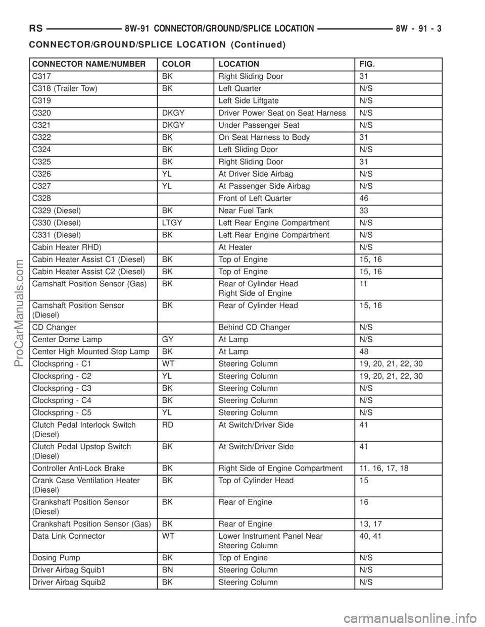
CONNECTOR NAME/NUMBER COLOR LOCATION FIG.
C317 BK Right Sliding Door 31
C318 (Trailer Tow) BK Left Quarter N/S
C319 Left Side Liftgate N/S
C320 DKGY Driver Power Seat on Seat Harness N/S
C321 DKGY Under Passenger Seat N/S
C322 BK On Seat Harness to Body 31
C324 BK Left Sliding Door N/S
C325 BK Right Sliding Door 31
C326 YL At Driver Side Airbag N/S
C327 YL At Passenger Side Airbag N/S
C328 Front of Left Quarter 46
C329 (Diesel) BK Near Fuel Tank 33
C330 (Diesel) LTGY Left Rear Engine Compartment N/S
C331 (Diesel) BK Left Rear Engine Compartment N/S
Cabin Heater RHD) At Heater N/S
Cabin Heater Assist C1 (Diesel) BK Top of Engine 15, 16
Cabin Heater Assist C2 (Diesel) BK Top of Engine 15, 16
Camshaft Position Sensor (Gas) BK Rear of Cylinder Head
Right Side of Engine11
Camshaft Position Sensor
(Diesel)BK Rear of Cylinder Head 15, 16
CD Changer Behind CD Changer N/S
Center Dome Lamp GY At Lamp N/S
Center High Mounted Stop Lamp BK At Lamp 48
Clockspring - C1 WT Steering Column 19, 20, 21, 22, 30
Clockspring - C2 YL Steering Column 19, 20, 21, 22, 30
Clockspring - C3 BK Steering Column N/S
Clockspring - C4 BK Steering Column N/S
Clockspring - C5 YL Steering Column N/S
Clutch Pedal Interlock Switch
(Diesel)RD At Switch/Driver Side 41
Clutch Pedal Upstop Switch
(Diesel)BK At Switch/Driver Side 41
Controller Anti-Lock Brake BK Right Side of Engine Compartment 11, 16, 17, 18
Crank Case Ventilation Heater
(Diesel)BK Top of Cylinder Head 15
Crankshaft Position Sensor
(Diesel)BK Rear of Engine 16
Crankshaft Position Sensor (Gas) BK Rear of Engine 13, 17
Data Link Connector WT Lower Instrument Panel Near
Steering Column40, 41
Dosing Pump BK Top of Engine N/S
Driver Airbag Squib1 BN Steering Column N/S
Driver Airbag Squib2 BK Steering Column N/S
RS8W-91 CONNECTOR/GROUND/SPLICE LOCATION8W-91-3
CONNECTOR/GROUND/SPLICE LOCATION (Continued)
ProCarManuals.com
Page 1122 of 2177
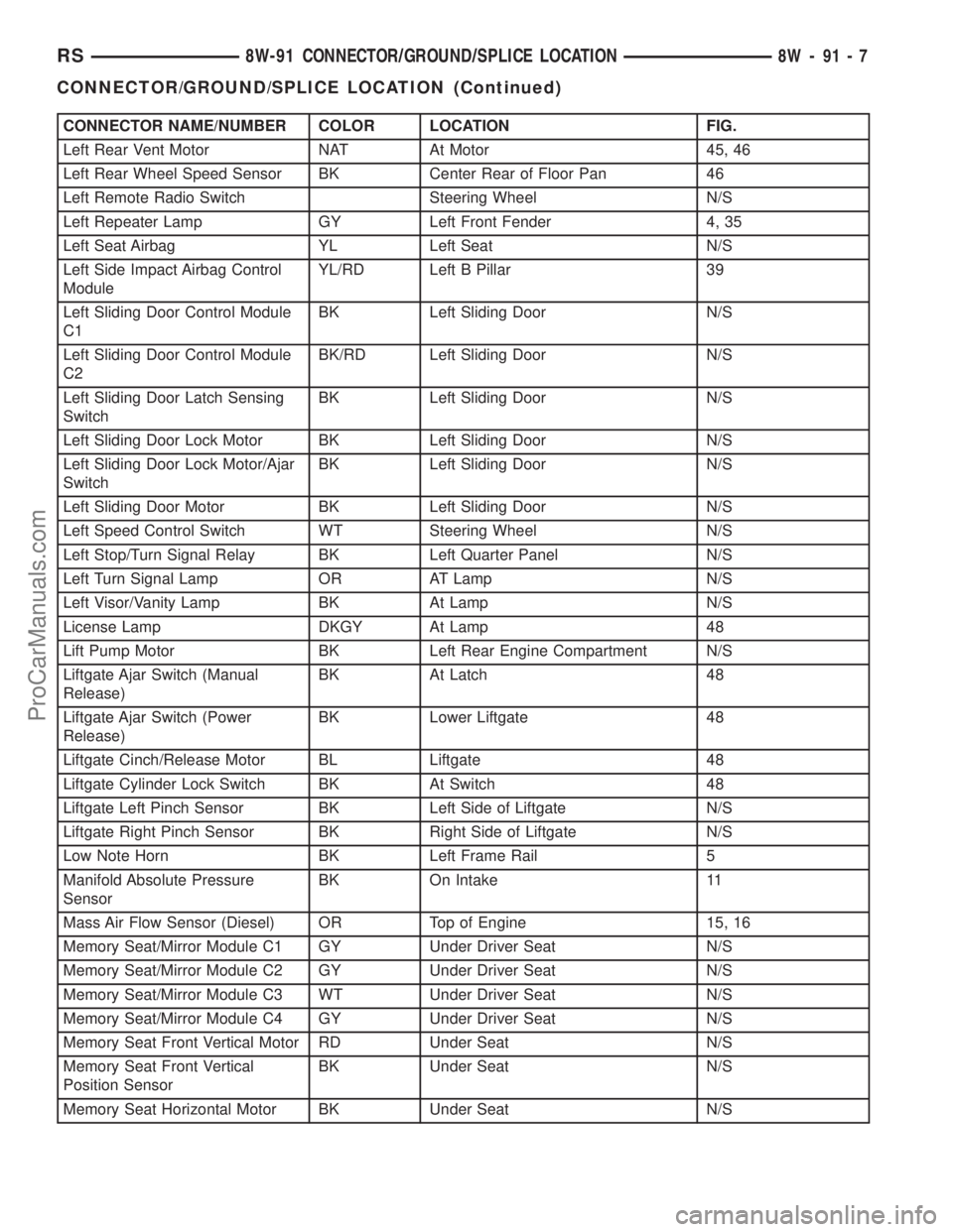
CONNECTOR NAME/NUMBER COLOR LOCATION FIG.
Left Rear Vent Motor NAT At Motor 45, 46
Left Rear Wheel Speed Sensor BK Center Rear of Floor Pan 46
Left Remote Radio Switch Steering Wheel N/S
Left Repeater Lamp GY Left Front Fender 4, 35
Left Seat Airbag YL Left Seat N/S
Left Side Impact Airbag Control
ModuleYL/RD Left B Pillar 39
Left Sliding Door Control Module
C1BK Left Sliding Door N/S
Left Sliding Door Control Module
C2BK/RD Left Sliding Door N/S
Left Sliding Door Latch Sensing
SwitchBK Left Sliding Door N/S
Left Sliding Door Lock Motor BK Left Sliding Door N/S
Left Sliding Door Lock Motor/Ajar
SwitchBK Left Sliding Door N/S
Left Sliding Door Motor BK Left Sliding Door N/S
Left Speed Control Switch WT Steering Wheel N/S
Left Stop/Turn Signal Relay BK Left Quarter Panel N/S
Left Turn Signal Lamp OR AT Lamp N/S
Left Visor/Vanity Lamp BK At Lamp N/S
License Lamp DKGY At Lamp 48
Lift Pump Motor BK Left Rear Engine Compartment N/S
Liftgate Ajar Switch (Manual
Release)BK At Latch 48
Liftgate Ajar Switch (Power
Release)BK Lower Liftgate 48
Liftgate Cinch/Release Motor BL Liftgate 48
Liftgate Cylinder Lock Switch BK At Switch 48
Liftgate Left Pinch Sensor BK Left Side of Liftgate N/S
Liftgate Right Pinch Sensor BK Right Side of Liftgate N/S
Low Note Horn BK Left Frame Rail 5
Manifold Absolute Pressure
SensorBK On Intake 11
Mass Air Flow Sensor (Diesel) OR Top of Engine 15, 16
Memory Seat/Mirror Module C1 GY Under Driver Seat N/S
Memory Seat/Mirror Module C2 GY Under Driver Seat N/S
Memory Seat/Mirror Module C3 WT Under Driver Seat N/S
Memory Seat/Mirror Module C4 GY Under Driver Seat N/S
Memory Seat Front Vertical Motor RD Under Seat N/S
Memory Seat Front Vertical
Position SensorBK Under Seat N/S
Memory Seat Horizontal Motor BK Under Seat N/S
RS8W-91 CONNECTOR/GROUND/SPLICE LOCATION8W-91-7
CONNECTOR/GROUND/SPLICE LOCATION (Continued)
ProCarManuals.com
Page 1123 of 2177

CONNECTOR NAME/NUMBER COLOR LOCATION FIG.
Memory Seat Horizontal Position
SensorBK Under Seat N/S
Memory Seat Rear Vertical Motor RD Under Seat N/S
Memory Seat Rear Vertical
Position SensorBK Under Seat N/S
Memory Seat Recliner Motor GN Under Seat N/S
Memory Seat Recliner Position
SensorBK Under Seat N/S
Memory Seat Switch BK At Switch Driver Door 42
Message Center WT Rear of Message Center 19, 20, 27
Mode Door Actuator GY Left Side of HVAC N/S
Multi Function Switch BK At Steering Column 19, 20, 21, 22, 30
Natural Vacuum Leak Detection
AssemblyBK Top of Engine 12
Output Speed Sensor GY Front of Transmission 14, 18
Overhead Console BK Front of Console N/S
Oxygen Sensor 1/1 Upstream BK Rear of Engine 10,11, 12, 18
Oxygen Sensor 1/2 Downstream BK Rear of Engine 10, 11, 12,18
Park/Neutral Positon Switch BK Front of Transmission 11
Passenger Airbag YL Passenger Side of Instrument Panel 19, 22, 23 28
Passenger Blend Door Actuator On HVAC N/S
Passenger Door Courtesy Lamp BK At Lamp 43
Passenger Door Lock Switch BK At Switch 43
Passenger Folding Mirror Relay BL Left Kick Panel 7
Passenger Heated Seat Back GN At Seat N/S
Passenger Heated Seat Cushion BK At Seat N/S
Passenger Heated Seat Module
C1GY At Heated Seat N/S
Passenger Heated Seat Module
C2GY At Heated Seat Back N/S
Passenger Heated Seat Module
C3GN At Heated Seat N/S
Passenger Power Seat Front
Riser MotorRD Under Seat N/S
Passenger Power Seat Horizontal
MotorBK Under Seat N/S
Passenger Power Seat Rear
Riser MotorRD Under Seat N/S
Passenger Power Seat Recliner
MotorGN Under Seat N/S
Passenger Power Seat Switch GN At Switch N/S
Passenger Power Window Motor RD At Motor 43
Passenger Power Window Switch BK At Switch 43
Passenger Seat Belt Switch On Seat Harness N/S
Passenger Seat Belt Tensioner On Seat Harness N/S
8W - 91 - 8 8W-91 CONNECTOR/GROUND/SPLICE LOCATIONRS
CONNECTOR/GROUND/SPLICE LOCATION (Continued)
ProCarManuals.com
Page 1125 of 2177
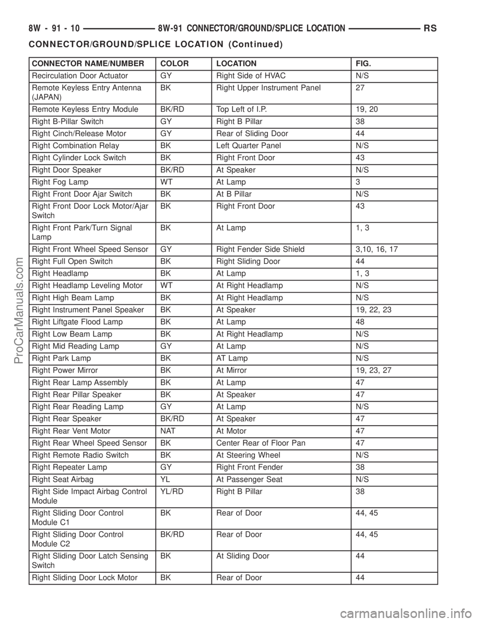
CONNECTOR NAME/NUMBER COLOR LOCATION FIG.
Recirculation Door Actuator GY Right Side of HVAC N/S
Remote Keyless Entry Antenna
(JAPAN)BK Right Upper Instrument Panel 27
Remote Keyless Entry Module BK/RD Top Left of I.P. 19, 20
Right B-Pillar Switch GY Right B Pillar 38
Right Cinch/Release Motor GY Rear of Sliding Door 44
Right Combination Relay BK Left Quarter Panel N/S
Right Cylinder Lock Switch BK Right Front Door 43
Right Door Speaker BK/RD At Speaker N/S
Right Fog Lamp WT At Lamp 3
Right Front Door Ajar Switch BK At B Pillar N/S
Right Front Door Lock Motor/Ajar
SwitchBK Right Front Door 43
Right Front Park/Turn Signal
LampBK At Lamp 1, 3
Right Front Wheel Speed Sensor GY Right Fender Side Shield 3,10, 16, 17
Right Full Open Switch BK Right Sliding Door 44
Right Headlamp BK At Lamp 1, 3
Right Headlamp Leveling Motor WT At Right Headlamp N/S
Right High Beam Lamp BK At Right Headlamp N/S
Right Instrument Panel Speaker BK At Speaker 19, 22, 23
Right Liftgate Flood Lamp BK At Lamp 48
Right Low Beam Lamp BK At Right Headlamp N/S
Right Mid Reading Lamp GY At Lamp N/S
Right Park Lamp BK AT Lamp N/S
Right Power Mirror BK At Mirror 19, 23, 27
Right Rear Lamp Assembly BK At Lamp 47
Right Rear Pillar Speaker BK At Speaker 47
Right Rear Reading Lamp GY At Lamp N/S
Right Rear Speaker BK/RD At Speaker 47
Right Rear Vent Motor NAT At Motor 47
Right Rear Wheel Speed Sensor BK Center Rear of Floor Pan 47
Right Remote Radio Switch BK At Steering Wheel N/S
Right Repeater Lamp GY Right Front Fender 38
Right Seat Airbag YL At Passenger Seat N/S
Right Side Impact Airbag Control
ModuleYL/RD Right B Pillar 38
Right Sliding Door Control
Module C1BK Rear of Door 44, 45
Right Sliding Door Control
Module C2BK/RD Rear of Door 44, 45
Right Sliding Door Latch Sensing
SwitchBK At Sliding Door 44
Right Sliding Door Lock Motor BK Rear of Door 44
8W - 91 - 10 8W-91 CONNECTOR/GROUND/SPLICE LOCATIONRS
CONNECTOR/GROUND/SPLICE LOCATION (Continued)
ProCarManuals.com
Page 1129 of 2177
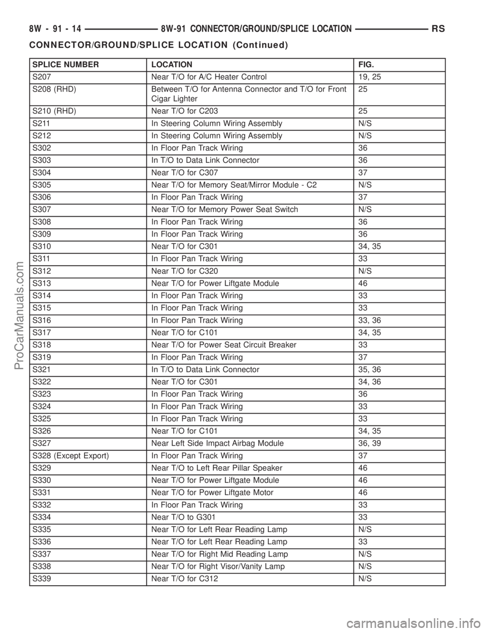
SPLICE NUMBER LOCATION FIG.
S207 Near T/O for A/C Heater Control 19, 25
S208 (RHD) Between T/O for Antenna Connector and T/O for Front
Cigar Lighter25
S210 (RHD) Near T/O for C203 25
S211 In Steering Column Wiring Assembly N/S
S212 In Steering Column Wiring Assembly N/S
S302 In Floor Pan Track Wiring 36
S303 In T/O to Data Link Connector 36
S304 Near T/O for C307 37
S305 Near T/O for Memory Seat/Mirror Module - C2 N/S
S306 In Floor Pan Track Wiring 37
S307 Near T/O for Memory Power Seat Switch N/S
S308 In Floor Pan Track Wiring 36
S309 In Floor Pan Track Wiring 36
S310 Near T/O for C301 34, 35
S311 In Floor Pan Track Wiring 33
S312 Near T/O for C320 N/S
S313 Near T/O for Power Liftgate Module 46
S314 In Floor Pan Track Wiring 33
S315 In Floor Pan Track Wiring 33
S316 In Floor Pan Track Wiring 33, 36
S317 Near T/O for C101 34, 35
S318 Near T/O for Power Seat Circuit Breaker 33
S319 In Floor Pan Track Wiring 37
S321 In T/O to Data Link Connector 35, 36
S322 Near T/O for C301 34, 36
S323 In Floor Pan Track Wiring 36
S324 In Floor Pan Track Wiring 33
S325 In Floor Pan Track Wiring 33
S326 Near T/O for C101 34, 35
S327 Near Left Side Impact Airbag Module 36, 39
S328 (Except Export) In Floor Pan Track Wiring 37
S329 Near T/O to Left Rear Pillar Speaker 46
S330 Near T/O for Power Liftgate Module 46
S331 Near T/O for Power Liftgate Motor 46
S332 In Floor Pan Track Wiring 33
S334 Near T/O to G301 33
S335 Near T/O for Left Rear Reading Lamp N/S
S336 Near T/O for Left Rear Reading Lamp 33
S337 Near T/O for Right Mid Reading Lamp N/S
S338 Near T/O for Right Visor/Vanity Lamp N/S
S339 Near T/O for C312 N/S
8W - 91 - 14 8W-91 CONNECTOR/GROUND/SPLICE LOCATIONRS
CONNECTOR/GROUND/SPLICE LOCATION (Continued)
ProCarManuals.com
Page 1179 of 2177
DIAGNOSIS AND TESTING
DIAGNOSIS & TESTING - POWER OUTLET
For complete circuit diagrams, refer toCigar
Lighter/Power Outletin Wiring Diagrams.
WARNING: ON VEHICLES EQUIPPED WITH AIR-
BAGS, REFER TO RESTRAINTS BEFORE ATTEMPT-
ING ANY STEERING WHEEL, STEERING COLUMN,
SEAT OR INSTRUMENT PANEL COMPONENT DIAG-
NOSIS OR SERVICE. FAILURE TO TAKE THE
PROPER PRECAUTIONS COULD RESULT IN ACCI-
DENTAL AIRBAG DEPLOYMENT AND POSSIBLE
PERSONAL INJURY.
(1) Check the fused B(+) fuse in the Integrated
Power Module (IPM). If OK, go to Step 2. If not OK,
repair the shorted circuit or component as required
and replace the faulty fuse.
(2) Check for battery voltage at the fused B(+) fuse
in the IPM. If OK, go to Step 3. If not OK, repair the
open fused B(+) circuit to the IPM fuse as required.
(3)
Open the power outlet door. Check for continuity
between the inside circumference of the power outlet
receptacle and a good ground. There should be continu-
ity. If OK, go to Step 4. If not OK, go to Step 5.
(4) Check for battery voltage at the insulated con-
tact located at the back of the power outlet recepta-
cle. If not OK, go to Step 5.
(5) Disconnect and isolate the battery negative
cable. Remove the appropriate bezel. Check for conti-
nuity between the ground circuit cavity of the power
outlet wire harness connector and a good ground.
There should be continuity. If OK, go to Step 6. If not
OK, repair the open ground circuit to ground as
required.
(6) Connect the battery negative cable. Check for
battery voltage at the fused B(+) circuit cavity of the
power outlet wire harness connector. If OK, replace
the faulty power outlet receptacle. If not OK, repair
the open fused B(+) circuit to the IPM fuse as
required.
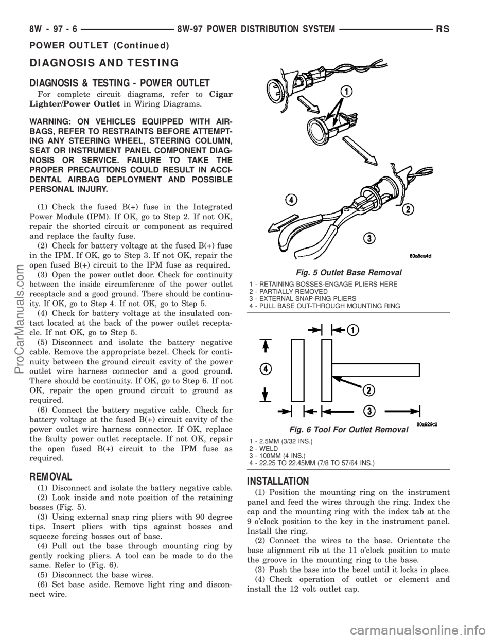
REMOVAL
(1)Disconnect and isolate the battery negative cable.
(2) Look inside and note position of the retaining
bosses (Fig. 5).
(3) Using external snap ring pliers with 90 degree
tips. Insert pliers with tips against bosses and
squeeze forcing bosses out of base.
(4) Pull out the base through mounting ring by
gently rocking pliers. A tool can be made to do the
same. Refer to (Fig. 6).
(5) Disconnect the base wires.
(6) Set base aside. Remove light ring and discon-
nect wire.
INSTALLATION
(1) Position the mounting ring on the instrument
panel and feed the wires through the ring. Index the
cap and the mounting ring with the index tab at the
9 o'clock position to the key in the instrument panel.
Install the ring.
(2) Connect the wires to the base. Orientate the
base alignment rib at the 11 o'clock position to mate
the groove in the mounting ring to the base.
(3)
Push the base into the bezel until it locks in place.
(4) Check operation of outlet or element and
install the 12 volt outlet cap.
Fig. 5 Outlet Base Removal
1 - RETAINING BOSSES-ENGAGE PLIERS HERE
2 - PARTIALLY REMOVED
3 - EXTERNAL SNAP-RING PLIERS
4 - PULL BASE OUT-THROUGH MOUNTING RING
Fig. 6 Tool For Outlet Removal
1 - 2.5MM (3/32 INS.)
2 - WELD
3 - 100MM (4 INS.)
4 - 22.25 TO 22.45MM (7/8 TO 57/64 INS.)
8W - 97 - 6 8W-97 POWER DISTRIBUTION SYSTEMRS
POWER OUTLET (Continued)
ProCarManuals.com