2003 CHRYSLER VOYAGER integrated power module
[x] Cancel search: integrated power modulePage 1059 of 2177
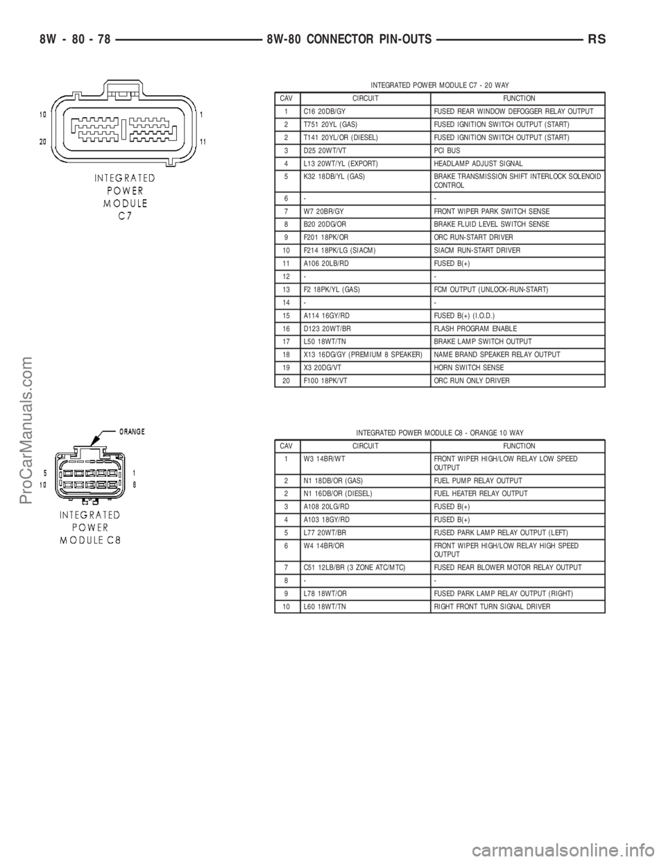
INTEGRATED POWER MODULE C7 - 20 WAY
CAV CIRCUIT FUNCTION
1 C16 20DB/GY FUSED REAR WINDOW DEFOGGER RELAY OUTPUT
2 T751 20YL (GAS) FUSED IGNITION SWITCH OUTPUT (START)
2 T141 20YL/OR (DIESEL) FUSED IGNITION SWITCH OUTPUT (START)
3 D25 20WT/VT PCI BUS
4 L13 20WT/YL (EXPORT) HEADLAMP ADJUST SIGNAL
5 K32 18DB/YL (GAS) BRAKE TRANSMISSION SHIFT INTERLOCK SOLENOID
CONTROL
6- -
7 W7 20BR/GY FRONT WIPER PARK SWITCH SENSE
8 B20 20DG/OR BRAKE FLUID LEVEL SWITCH SENSE
9 F201 18PK/OR ORC RUN-START DRIVER
10 F214 18PK/LG (SIACM) SIACM RUN-START DRIVER
11 A106 20LB/RD FUSED B(+)
12 - -
13 F2 18PK/YL (GAS) FCM OUTPUT (UNLOCK-RUN-START)
14 - -
15 A114 16GY/RD FUSED B(+) (I.O.D.)
16 D123 20WT/BR FLASH PROGRAM ENABLE
17 L50 18WT/TN BRAKE LAMP SWITCH OUTPUT
18 X13 16DG/GY (PREMIUM 8 SPEAKER) NAME BRAND SPEAKER RELAY OUTPUT
19 X3 20DG/VT HORN SWITCH SENSE
20 F100 18PK/VT ORC RUN ONLY DRIVER
INTEGRATED POWER MODULE C8 - ORANGE 10 WAY
CAV CIRCUIT FUNCTION
1 W3 14BR/WT FRONT WIPER HIGH/LOW RELAY LOW SPEED
OUTPUT
2 N1 18DB/OR (GAS) FUEL PUMP RELAY OUTPUT
2 N1 16DB/OR (DIESEL) FUEL HEATER RELAY OUTPUT
3 A108 20LG/RD FUSED B(+)
4 A103 18GY/RD FUSED B(+)
5 L77 20WT/BR FUSED PARK LAMP RELAY OUTPUT (LEFT)
6 W4 14BR/OR FRONT WIPER HIGH/LOW RELAY HIGH SPEED
OUTPUT
7 C51 12LB/BR (3 ZONE ATC/MTC) FUSED REAR BLOWER MOTOR RELAY OUTPUT
8- -
9 L78 18WT/OR FUSED PARK LAMP RELAY OUTPUT (RIGHT)
10 L60 18WT/TN RIGHT FRONT TURN SIGNAL DRIVER
8W - 80 - 78 8W-80 CONNECTOR PIN-OUTSRS
ProCarManuals.com
Page 1060 of 2177
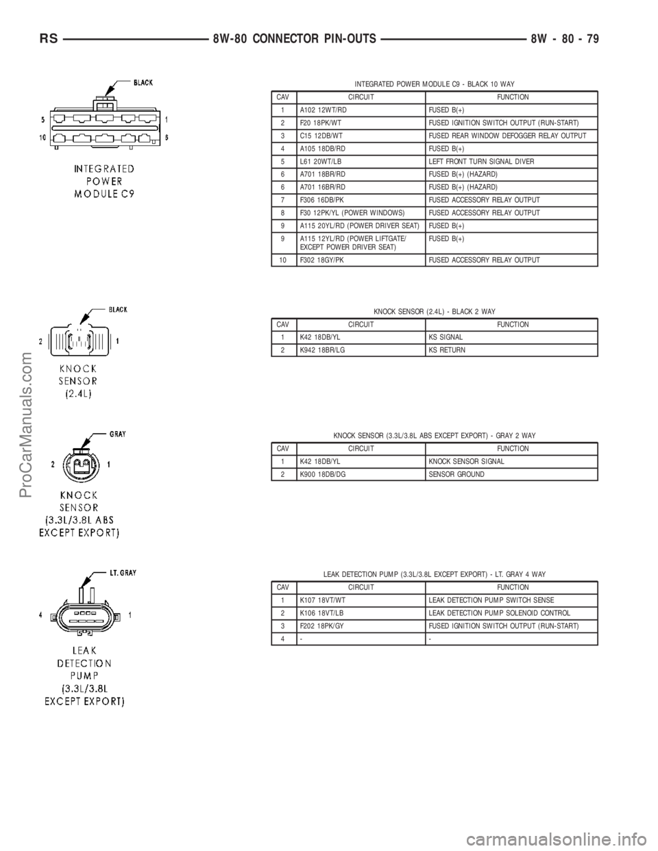
INTEGRATED POWER MODULE C9 - BLACK 10 WAY
CAV CIRCUIT FUNCTION
1 A102 12WT/RD FUSED B(+)
2 F20 18PK/WT FUSED IGNITION SWITCH OUTPUT (RUN-START)
3 C15 12DB/WT FUSED REAR WINDOW DEFOGGER RELAY OUTPUT
4 A105 18DB/RD FUSED B(+)
5 L61 20WT/LB LEFT FRONT TURN SIGNAL DIVER
6 A701 18BR/RD FUSED B(+) (HAZARD)
6 A701 16BR/RD FUSED B(+) (HAZARD)
7 F306 16DB/PK FUSED ACCESSORY RELAY OUTPUT
8 F30 12PK/YL (POWER WINDOWS) FUSED ACCESSORY RELAY OUTPUT
9 A115 20YL/RD (POWER DRIVER SEAT) FUSED B(+)
9 A115 12YL/RD (POWER LIFTGATE/
EXCEPT POWER DRIVER SEAT)FUSED B(+)
10 F302 18GY/PK FUSED ACCESSORY RELAY OUTPUT
KNOCK SENSOR (2.4L) - BLACK 2 WAY
CAV CIRCUIT FUNCTION
1 K42 18DB/YL KS SIGNAL
2 K942 18BR/LG KS RETURN
KNOCK SENSOR (3.3L/3.8L ABS EXCEPT EXPORT) - GRAY 2 WAY
CAV CIRCUIT FUNCTION
1 K42 18DB/YL KNOCK SENSOR SIGNAL
2 K900 18DB/DG SENSOR GROUND
LEAK DETECTION PUMP (3.3L/3.8L EXCEPT EXPORT) - LT. GRAY 4 WAY
CAV CIRCUIT FUNCTION
1 K107 18VT/WT LEAK DETECTION PUMP SWITCH SENSE
2 K106 18VT/LB LEAK DETECTION PUMP SOLENOID CONTROL
3 F202 18PK/GY FUSED IGNITION SWITCH OUTPUT (RUN-START)
4- -
RS8W-80 CONNECTOR PIN-OUTS8W-80-79
ProCarManuals.com
Page 1121 of 2177
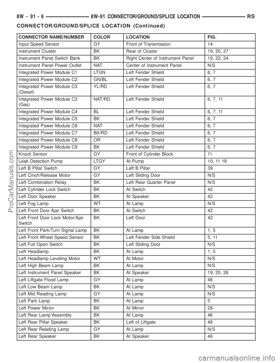
CONNECTOR NAME/NUMBER COLOR LOCATION FIG.
Input Speed Sensor GY Front of Transmission 14
Instrument Cluster BK Rear of Cluster 19, 20, 27
Instrument Panel Switch Bank BK Right Center of Instrument Panel 19, 22, 24
Instrument Panel Power Outlet NAT Center of Instrument Panel N/S
Integrated Power Module C1 LTGN Left Fender Shield 6, 7
Integrated Power Module C2 GN/BL Left Fender Shield 6, 7
Integrated Power Module C3
(Diesel)YL/RD Left Fender Shield 6, 7
Integrated Power Module C3
(Gas)NAT/RD Left Fender Shield 6, 7, 11
Integrated Power Module C4 BL Left Fender Shield 6, 7, 11
Integrated Power Module C5 BK Left Fender Shield 6, 7
Integrated Power Module C6 NAT Left Fender Shield 6, 7
Integrated Power Module C7 BK/RD Left Fender Shield 6, 7
Integrated Power Module C8 OR Left Fender Shield 6, 7
Integrated Power Module C9 BK Left Fender Shield 6, 7
Knock Sensor GY Front of Cylinder Block 11
Leak Detection Pump LTGY At Pump 10, 11 18
Left B Pillar Switch GY Left B Pillar 39
Left Cinch/Release Motor GY Left Sliding Door N/S
Left Combination Relay BK Left Rear Quarter Panel N/S
Left Cylinder Lock Switch BK At Switch 42
Left Door Speaker BK At Speaker 42
Left Fog Lamp WT At Lamp N/S
Left Front Door Ajar Switch BK At Switch 42
Left Front Door Lock Motor/Ajar
SwitchBK Left Door 42
Left Front Park/Turn Signal Lamp BK At Lamp 1, 5
Left Front Wheel Speed Sensor BK Left Fender Side Shield 5, 11
Left Full Open Switch BK Left Sliding Door N/S
Left Headlamp BK At Lamp 1, 5
Left Headlamp Leveling Motor WT At Motor N/S
Left High Beam Lamp BK At Lamp N/S
Left Instrument Panel Speaker BK At Speaker 19, 20, 26
Left Liftgate Flood Lamp GY At Lamp 48
Left Low Beam Lamp BK At Lamp N/S
Left Mid Reading Lamp GY At Lamp N/S
Left Park Lamp BK At Lamp 5
Left Power Mirror BK At Mirror 26
Left Rear Lamp Assembly BK At Lamp 46
Left Rear Pillar Speaker BK Left of Liftgate 46
Left Rear Reading Lamp GY At Lamp N/S
Left Rear Speaker BK At Speaker 46
8W - 91 - 6 8W-91 CONNECTOR/GROUND/SPLICE LOCATIONRS
CONNECTOR/GROUND/SPLICE LOCATION (Continued)
ProCarManuals.com
Page 1127 of 2177
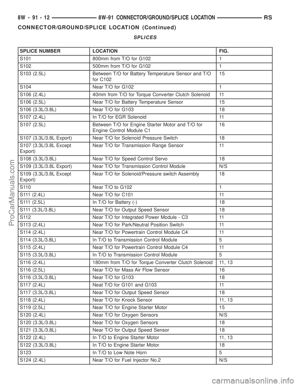
SPLICES
SPLICE NUMBER LOCATION FIG.
S101 800mm from T/O for G102 1
S102 500mm from T/O for G102 1
S103 (2.5L) Between T/O for Battery Temperature Sensor and T/O
for C10215
S104 Near T/O for G102 1
S106 (2.4L) 40mm from T/O for Torque Converter Clutch Solenoid 11
S106 (2.5L) Near T/O for Battery Temperature Sensor 15
S106 (3.3L/3.8L) Near T/O for G103 18
S107 (2.4L) In T/O for EGR Solenoid 11
S107 (2.5L) Between T/O for Engine Starter Motor and T/O for
Engine Control Module C116
S107 (3.3L/3.8L Export) Near T/O for Solenoid Pressure Switch 18
S107 (3.3L/3.8L Except
Export)Near T/O for Transmission Range Sensor 11
S108 (3.3L/3.8L) Near T/O for Speed Control Servo 18
S109 (3.3L/3.8L Export) Near T/O for Transmission Control Module N/S
S109 (3.3L/3.8L Except
Export)Near T/O for Solenoid/Pressure switch Assembly 18
S110 Near T/O to G102 1
S111 (2.4L) Near T/O for C101 11
S111 (2.5L) In T/O for Battery (-) 18
S111 (3.3L/3.8L) Near T/O for Output Speed Sensor 18
S112 Near T/O for Integrated Power Module - C3 11
S113 (2.4L) Near T/O for Park/Neutral Position Switch 11
S114 (2.4L) Near T/O for Powertrain Control Module C4 11
S114 (3.3L/3.8L) In T/O to Transmission Control Module 5
S115 (2.4L) Near T/O for Powertrain Control Module C4 11
S115 (3.3L/3.8L) In T/O to Transmission Control Module 5
S116 (2.4L) 180mm from T/O for Torque Converter Clutch Solenoid 11, 13
S116 (2.5L) Near T/O for Mass Air Flow Sensor 16
S116 (3.3L/3.8L) Near T/O for G103 18
S117 (2.4L) Neat T/O for G101 and G103 11
S117 (3.3L/3.8L) Near T/O for Output Speed Sensor 18
S118 (2.4L) Near T/O for Knock Sensor 11, 13
S119 (2.5L) Near T/O for Engine Starter Motor 15
S120 (2.4L) Near T/O for Oxygen Sensors N/S
S120 (3.3L/3.8L) Near T/O for Oxygen Sensors 18
S121 (3.3L/3.8L) Near T/O for Output Speed Sensor 18
S122 (2.4L) In T/O to Engine Starter Motor 11, 13
S122 (3.3L/3.8L) In T/O to Engine Starter Motor 18
S123 In T/O to Low Note Horn 5
S124 (2.4L) Near T/O for Fuel Injector No.2 N/S
8W - 91 - 12 8W-91 CONNECTOR/GROUND/SPLICE LOCATIONRS
CONNECTOR/GROUND/SPLICE LOCATION (Continued)
ProCarManuals.com
Page 1128 of 2177
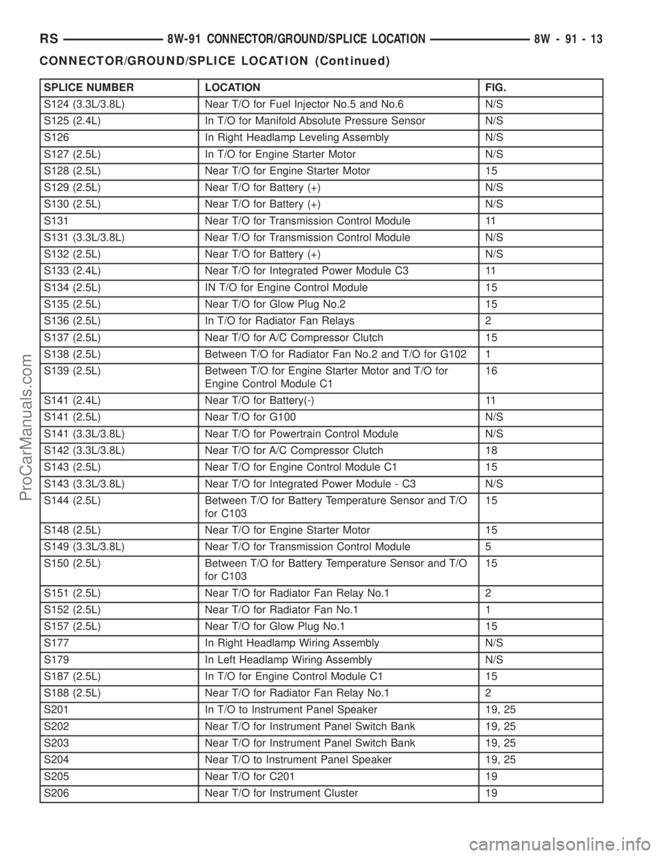
SPLICE NUMBER LOCATION FIG.
S124 (3.3L/3.8L) Near T/O for Fuel Injector No.5 and No.6 N/S
S125 (2.4L) In T/O for Manifold Absolute Pressure Sensor N/S
S126 In Right Headlamp Leveling Assembly N/S
S127 (2.5L) In T/O for Engine Starter Motor N/S
S128 (2.5L) Near T/O for Engine Starter Motor 15
S129 (2.5L) Near T/O for Battery (+) N/S
S130 (2.5L) Near T/O for Battery (+) N/S
S131 Near T/O for Transmission Control Module 11
S131 (3.3L/3.8L) Near T/O for Transmission Control Module N/S
S132 (2.5L) Near T/O for Battery (+) N/S
S133 (2.4L) Near T/O for Integrated Power Module C3 11
S134 (2.5L) IN T/O for Engine Control Module 15
S135 (2.5L) Near T/O for Glow Plug No.2 15
S136 (2.5L) In T/O for Radiator Fan Relays 2
S137 (2.5L) Near T/O for A/C Compressor Clutch 15
S138 (2.5L) Between T/O for Radiator Fan No.2 and T/O for G102 1
S139 (2.5L) Between T/O for Engine Starter Motor and T/O for
Engine Control Module C116
S141 (2.4L) Near T/O for Battery(-) 11
S141 (2.5L) Near T/O for G100 N/S
S141 (3.3L/3.8L) Near T/O for Powertrain Control Module N/S
S142 (3.3L/3.8L) Near T/O for A/C Compressor Clutch 18
S143 (2.5L) Near T/O for Engine Control Module C1 15
S143 (3.3L/3.8L) Near T/O for Integrated Power Module - C3 N/S
S144 (2.5L) Between T/O for Battery Temperature Sensor and T/O
for C10315
S148 (2.5L) Near T/O for Engine Starter Motor 15
S149 (3.3L/3.8L) Near T/O for Transmission Control Module 5
S150 (2.5L) Between T/O for Battery Temperature Sensor and T/O
for C10315
S151 (2.5L) Near T/O for Radiator Fan Relay No.1 2
S152 (2.5L) Near T/O for Radiator Fan No.1 1
S157 (2.5L) Near T/O for Glow Plug No.1 15
S177 In Right Headlamp Wiring Assembly N/S
S179 In Left Headlamp Wiring Assembly N/S
S187 (2.5L) In T/O for Engine Control Module C1 15
S188 (2.5L) Near T/O for Radiator Fan Relay No.1 2
S201 In T/O to Instrument Panel Speaker 19, 25
S202 Near T/O for Instrument Panel Switch Bank 19, 25
S203 Near T/O for Instrument Panel Switch Bank 19, 25
S204 Near T/O to Instrument Panel Speaker 19, 25
S205 Near T/O for C201 19
S206 Near T/O for Instrument Cluster 19
RS8W-91 CONNECTOR/GROUND/SPLICE LOCATION8W-91-13
CONNECTOR/GROUND/SPLICE LOCATION (Continued)
ProCarManuals.com
Page 1130 of 2177
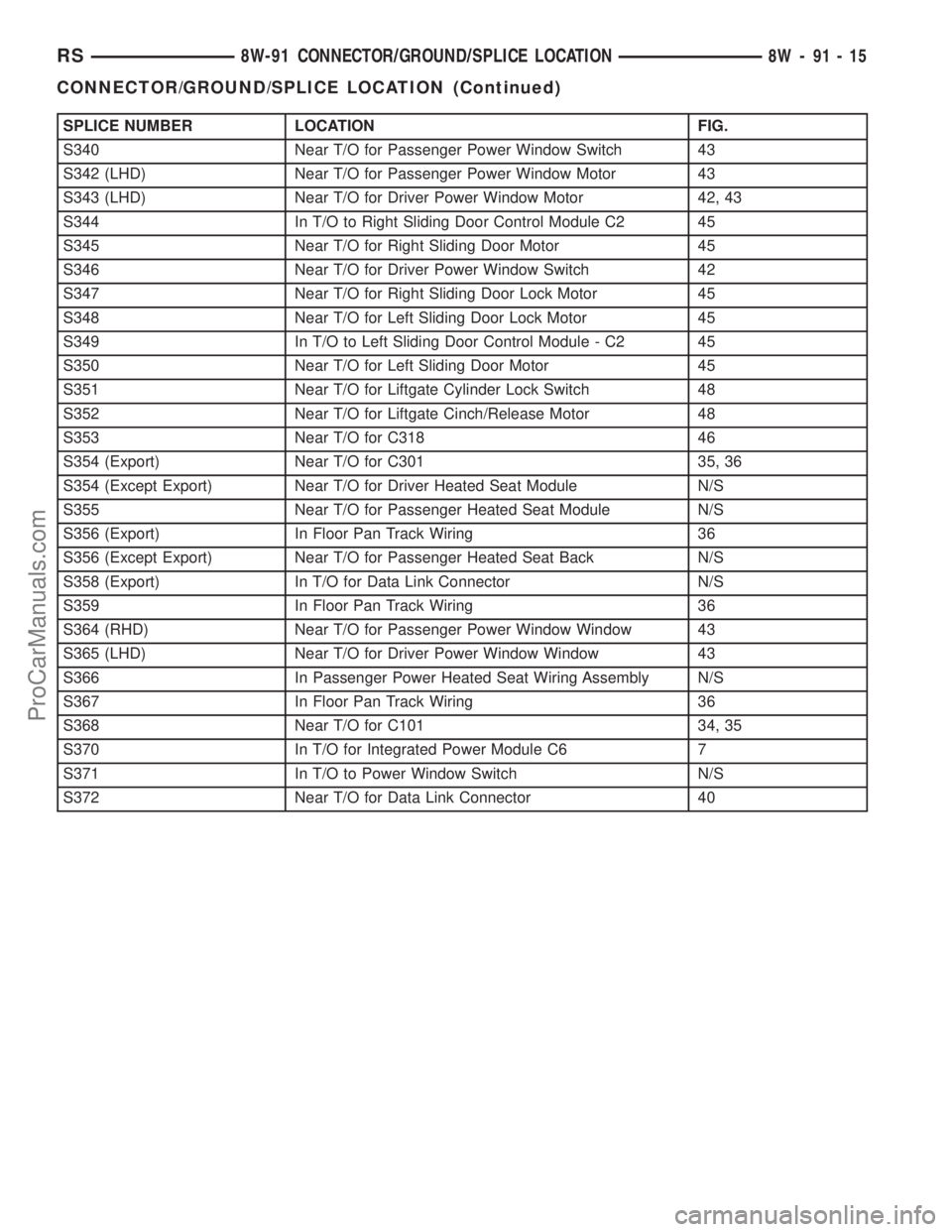
SPLICE NUMBER LOCATION FIG.
S340 Near T/O for Passenger Power Window Switch 43
S342 (LHD) Near T/O for Passenger Power Window Motor 43
S343 (LHD) Near T/O for Driver Power Window Motor 42, 43
S344 In T/O to Right Sliding Door Control Module C2 45
S345 Near T/O for Right Sliding Door Motor 45
S346 Near T/O for Driver Power Window Switch 42
S347 Near T/O for Right Sliding Door Lock Motor 45
S348 Near T/O for Left Sliding Door Lock Motor 45
S349 In T/O to Left Sliding Door Control Module - C2 45
S350 Near T/O for Left Sliding Door Motor 45
S351 Near T/O for Liftgate Cylinder Lock Switch 48
S352 Near T/O for Liftgate Cinch/Release Motor 48
S353 Near T/O for C318 46
S354 (Export) Near T/O for C301 35, 36
S354 (Except Export) Near T/O for Driver Heated Seat Module N/S
S355 Near T/O for Passenger Heated Seat Module N/S
S356 (Export) In Floor Pan Track Wiring 36
S356 (Except Export) Near T/O for Passenger Heated Seat Back N/S
S358 (Export) In T/O for Data Link Connector N/S
S359 In Floor Pan Track Wiring 36
S364 (RHD) Near T/O for Passenger Power Window Window 43
S365 (LHD) Near T/O for Driver Power Window Window 43
S366 In Passenger Power Heated Seat Wiring Assembly N/S
S367 In Floor Pan Track Wiring 36
S368 Near T/O for C101 34, 35
S370 In T/O for Integrated Power Module C6 7
S371 In T/O to Power Window Switch N/S
S372 Near T/O for Data Link Connector 40
RS8W-91 CONNECTOR/GROUND/SPLICE LOCATION8W-91-15
CONNECTOR/GROUND/SPLICE LOCATION (Continued)
ProCarManuals.com
Page 1136 of 2177
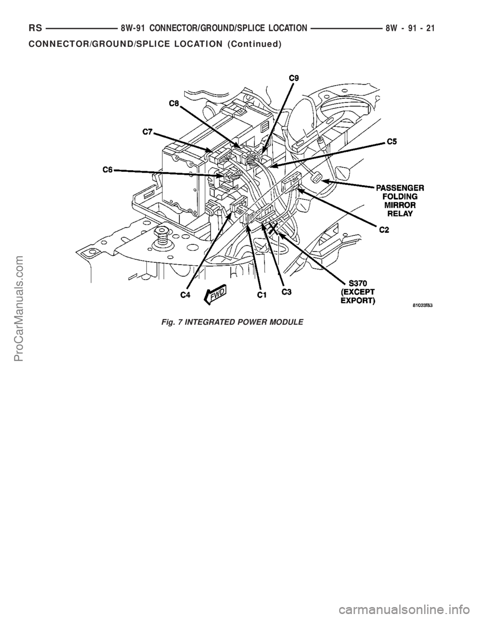
Fig. 7 INTEGRATED POWER MODULE
RS8W-91 CONNECTOR/GROUND/SPLICE LOCATION8W-91-21
CONNECTOR/GROUND/SPLICE LOCATION (Continued)
ProCarManuals.com
Page 1174 of 2177
8W-97 POWER DISTRIBUTION SYSTEM
TABLE OF CONTENTS
page page
POWER DISTRIBUTION SYSTEM
DESCRIPTION..........................1
OPERATION............................1
SPECIAL TOOLS
POWER DISTRIBUTION SYSTEMS.........2
ACCESSORY RELAY
DESCRIPTION..........................2
OPERATION............................2
DIAGNOSIS AND TESTING
DIAGNOSIS & TESTING - ACCESSORY
RELAY...............................2
REMOVAL.............................3
INSTALLATION..........................3
INTEGRATED POWER MODULE
DESCRIPTION..........................3OPERATION............................3
REMOVAL.............................4
INSTALLATION..........................4
IOD FUSE
DESCRIPTION..........................4
OPERATION............................5
REMOVAL.............................5
INSTALLATION..........................5
POWER OUTLET
DESCRIPTION..........................5
OPERATION............................5
DIAGNOSIS AND TESTING
DIAGNOSIS & TESTING - POWER OUTLET . . 6
REMOVAL.............................6
INSTALLATION..........................6
POWER DISTRIBUTION
SYSTEM
DESCRIPTION
This group covers the various standard and
optional power distribution components used on this
model. The power distribution system for this vehicle
consists of the following components:
²Integrated Power Module (IPM)
²Front Control Module (FCM)
²Power Outlets
Refer to Wiring Diagrams for complete circuit sche-
matics.
The power distribution system also incorporates
various types of circuit control and protection fea-
tures, including:
²Automatic resetting circuit breakers
²Blade-type fuses
²Bus bars
²Cartridge fuses
²Circuit splice blocks
²Flashers
²Fusible links
²RelaysFollowing are general descriptions of the major
components in the power distribution system. See the
owner's manual in the vehicle glove box for more
information on the features and use of all of the
power distribution system components.
OPERATION
The power distribution system for this vehicle is
designed to provide safe, reliable, and centralized dis-
tribution points for the electrical current required to
operate all of the many standard and optional facto-
ry-installed electrical and electronic powertrain,
chassis, safety, security, comfort and convenience sys-
tems. At the same time, the power distribution sys-
tem was designed to provide ready access to these
electrical distribution points for the vehicle techni-
cian to use when conducting diagnosis and repair of
faulty circuits. The power distribution system can
also prove useful for the sourcing of additional elec-
trical circuits that may be required to provide the
electrical current needed to operate many accessories
that the vehicle owner may choose to have installed
in the aftermarket.
RS8W-97 POWER DISTRIBUTION SYSTEM8W-97-1
ProCarManuals.com