2003 CHRYSLER VOYAGER electronic control modules
[x] Cancel search: electronic control modulesPage 1571 of 2177
TORQUE CONVERTER LEAKAGE
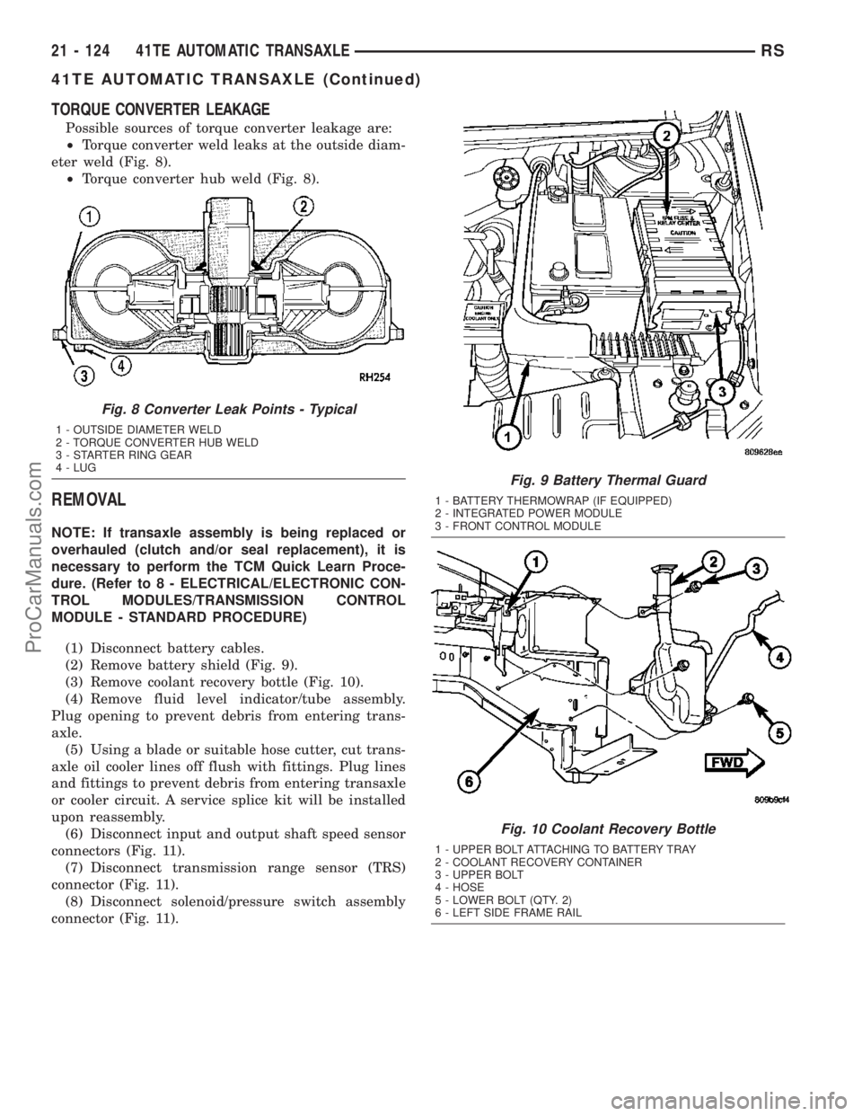
Possible sources of torque converter leakage are:
²Torque converter weld leaks at the outside diam-
eter weld (Fig. 8).
²Torque converter hub weld (Fig. 8).
REMOVAL
NOTE: If transaxle assembly is being replaced or
overhauled (clutch and/or seal replacement), it is
necessary to perform the TCM Quick Learn Proce-
dure. (Refer to 8 - ELECTRICAL/ELECTRONIC CON-
TROL MODULES/TRANSMISSION CONTROL
MODULE - STANDARD PROCEDURE)
(1) Disconnect battery cables.
(2) Remove battery shield (Fig. 9).
(3) Remove coolant recovery bottle (Fig. 10).
(4) Remove fluid level indicator/tube assembly.
Plug opening to prevent debris from entering trans-
axle.
(5) Using a blade or suitable hose cutter, cut trans-
axle oil cooler lines off flush with fittings. Plug lines
and fittings to prevent debris from entering transaxle
or cooler circuit. A service splice kit will be installed
upon reassembly.
(6) Disconnect input and output shaft speed sensor
connectors (Fig. 11).
(7) Disconnect transmission range sensor (TRS)
connector (Fig. 11).
(8) Disconnect solenoid/pressure switch assembly
connector (Fig. 11).
Fig. 8 Converter Leak Points - Typical
1 - OUTSIDE DIAMETER WELD
2 - TORQUE CONVERTER HUB WELD
3 - STARTER RING GEAR
4 - LUG
Fig. 9 Battery Thermal Guard
1 - BATTERY THERMOWRAP (IF EQUIPPED)
2 - INTEGRATED POWER MODULE
3 - FRONT CONTROL MODULE
Fig. 10 Coolant Recovery Bottle
1 - UPPER BOLT ATTACHING TO BATTERY TRAY
2 - COOLANT RECOVERY CONTAINER
3 - UPPER BOLT
4 - HOSE
5 - LOWER BOLT (QTY. 2)
6 - LEFT SIDE FRAME RAIL
21 - 124 41TE AUTOMATIC TRANSAXLERS
41TE AUTOMATIC TRANSAXLE (Continued)
ProCarManuals.com
Page 1572 of 2177
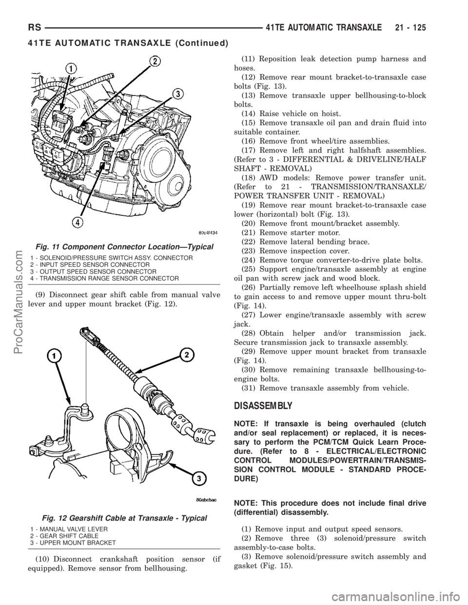
(9) Disconnect gear shift cable from manual valve
lever and upper mount bracket (Fig. 12).
(10) Disconnect crankshaft position sensor (if
equipped). Remove sensor from bellhousing.(11) Reposition leak detection pump harness and
hoses.
(12) Remove rear mount bracket-to-transaxle case
bolts (Fig. 13).
(13) Remove transaxle upper bellhousing-to-block
bolts.
(14) Raise vehicle on hoist.
(15) Remove transaxle oil pan and drain fluid into
suitable container.
(16) Remove front wheel/tire assemblies.
(17) Remove left and right halfshaft assemblies.
(Refer to 3 - DIFFERENTIAL & DRIVELINE/HALF
SHAFT - REMOVAL)
(18) AWD models: Remove power transfer unit.
(Refer to 21 - TRANSMISSION/TRANSAXLE/
POWER TRANSFER UNIT - REMOVAL)
(19) Remove rear mount bracket-to-transaxle case
lower (horizontal) bolt (Fig. 13).
(20) Remove front mount/bracket assembly.
(21) Remove starter motor.
(22) Remove lateral bending brace.
(23) Remove inspection cover.
(24) Remove torque converter-to-drive plate bolts.
(25) Support engine/transaxle assembly at engine
oil pan with screw jack and wood block.
(26) Partially remove left wheelhouse splash shield
to gain access to and remove upper mount thru-bolt
(Fig. 14).
(27) Lower engine/transaxle assembly with screw
jack.
(28) Obtain helper and/or transmission jack.
Secure transmission jack to transaxle assembly.
(29) Remove upper mount bracket from transaxle
(Fig. 14).
(30) Remove remaining transaxle bellhousing-to-
engine bolts.
(31) Remove transaxle assembly from vehicle.
DISASSEMBLY
NOTE: If transaxle is being overhauled (clutch
and/or seal replacement) or replaced, it is neces-
sary to perform the PCM/TCM Quick Learn Proce-
dure. (Refer to 8 - ELECTRICAL/ELECTRONIC
CONTROL MODULES/POWERTRAIN/TRANSMIS-
SION CONTROL MODULE - STANDARD PROCE-
DURE)
NOTE: This procedure does not include final drive
(differential) disassembly.
(1) Remove input and output speed sensors.
(2) Remove three (3) solenoid/pressure switch
assembly-to-case bolts.
(3) Remove solenoid/pressure switch assembly and
gasket (Fig. 15).
Fig. 11 Component Connector LocationÐTypical
1 - SOLENOID/PRESSURE SWITCH ASSY. CONNECTOR
2 - INPUT SPEED SENSOR CONNECTOR
3 - OUTPUT SPEED SENSOR CONNECTOR
4 - TRANSMISSION RANGE SENSOR CONNECTOR
Fig. 12 Gearshift Cable at Transaxle - Typical
1 - MANUAL VALVE LEVER
2 - GEAR SHIFT CABLE
3 - UPPER MOUNT BRACKET
RS41TE AUTOMATIC TRANSAXLE21 - 125
41TE AUTOMATIC TRANSAXLE (Continued)
ProCarManuals.com
Page 1591 of 2177
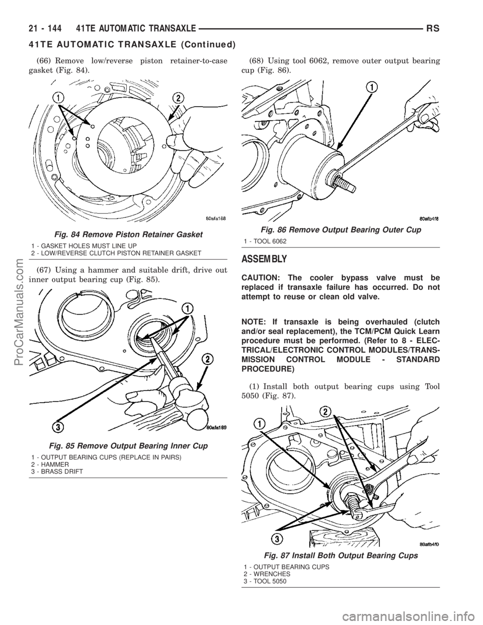
(66) Remove low/reverse piston retainer-to-case
gasket (Fig. 84).
(67) Using a hammer and suitable drift, drive out
inner output bearing cup (Fig. 85).(68) Using tool 6062, remove outer output bearing
cup (Fig. 86).
ASSEMBLY
CAUTION: The cooler bypass valve must be
replaced if transaxle failure has occurred. Do not
attempt to reuse or clean old valve.
NOTE: If transaxle is being overhauled (clutch
and/or seal replacement), the TCM/PCM Quick Learn
procedure must be performed. (Refer to 8 - ELEC-
TRICAL/ELECTRONIC CONTROL MODULES/TRANS-
MISSION CONTROL MODULE - STANDARD
PROCEDURE)
(1) Install both output bearing cups using Tool
5050 (Fig. 87).
Fig. 84 Remove Piston Retainer Gasket
1 - GASKET HOLES MUST LINE UP
2 - LOW/REVERSE CLUTCH PISTON RETAINER GASKET
Fig. 85 Remove Output Bearing Inner Cup
1 - OUTPUT BEARING CUPS (REPLACE IN PAIRS)
2 - HAMMER
3 - BRASS DRIFT
Fig. 86 Remove Output Bearing Outer Cup
1 - TOOL 6062
Fig. 87 Install Both Output Bearing Cups
1 - OUTPUT BEARING CUPS
2 - WRENCHES
3 - TOOL 5050
21 - 144 41TE AUTOMATIC TRANSAXLERS
41TE AUTOMATIC TRANSAXLE (Continued)
ProCarManuals.com
Page 1613 of 2177
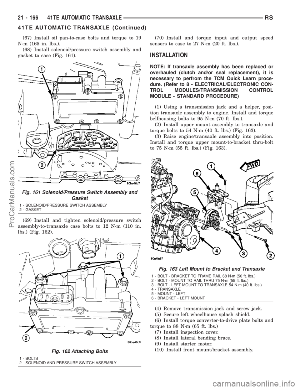
(67) Install oil pan-to-case bolts and torque to 19
N´m (165 in. lbs.).
(68) Install solenoid/pressure switch assembly and
gasket to case (Fig. 161).
(69) Install and tighten solenoid/pressure switch
assembly-to-transaxle case bolts to 12 N´m (110 in.
lbs.) (Fig. 162).(70) Install and torque input and output speed
sensors to case to 27 N´m (20 ft. lbs.).
INSTALLATION
NOTE: If transaxle assembly has been replaced or
overhauled (clutch and/or seal replacement), it is
necessary to perfrom the TCM Quick Learn proce-
dure. (Refer to 8 - ELECTRICAL/ELECTRONIC CON-
TROL MODULES/TRANSMISSION CONTROL
MODULE - STANDARD PROCEDURE)
(1) Using a transmission jack and a helper, posi-
tion transaxle assembly to engine. Install and torque
bellhousing bolts to 95 N´m (70 ft. lbs.).
(2) Install upper mount assembly to transaxle and
torque bolts to 54 N´m (40 ft. lbs.) (Fig. 163).
(3) Raise engine/transaxle assembly into position.
Install and torque upper mount-to-bracket thru-bolt
to 75 N´m (55 ft. lbs.) (Fig. 163).
(4) Remove transmission jack and screw jack.
(5) Secure left wheelhouse splash shield.
(6) Install torque converter-to-drive plate bolts and
torque to 88 N´m (65 ft. lbs.)
(7) Install inspection cover.
(8) Install lateral bending brace.
(9) Install starter motor.
(10) Install front mount/bracket assembly.
Fig. 161 Solenoid/Pressure Switch Assembly and
Gasket
1 - SOLENOID/PRESSURE SWITCH ASSEMBLY
2 - GASKET
Fig. 162 Attaching Bolts
1 - BOLTS
2 - SOLENOID AND PRESSURE SWITCH ASSEMBLY
Fig. 163 Left Mount to Bracket and Transaxle
1 - BOLT - BRACKET TO FRAME RAIL 68 N´m (50 ft. lbs.)
2 - BOLT - MOUNT TO RAIL THRU 75 N´m (55 ft. lbs.)
3 - BOLT - LEFT MOUNT TO TRANSAXLE 54 N´m (40 ft. lbs.)
4 - TRANSAXLE
5 - MOUNT - LEFT
6 - BRACKET - LEFT MOUNT
21 - 166 41TE AUTOMATIC TRANSAXLERS
41TE AUTOMATIC TRANSAXLE (Continued)
ProCarManuals.com
Page 1685 of 2177
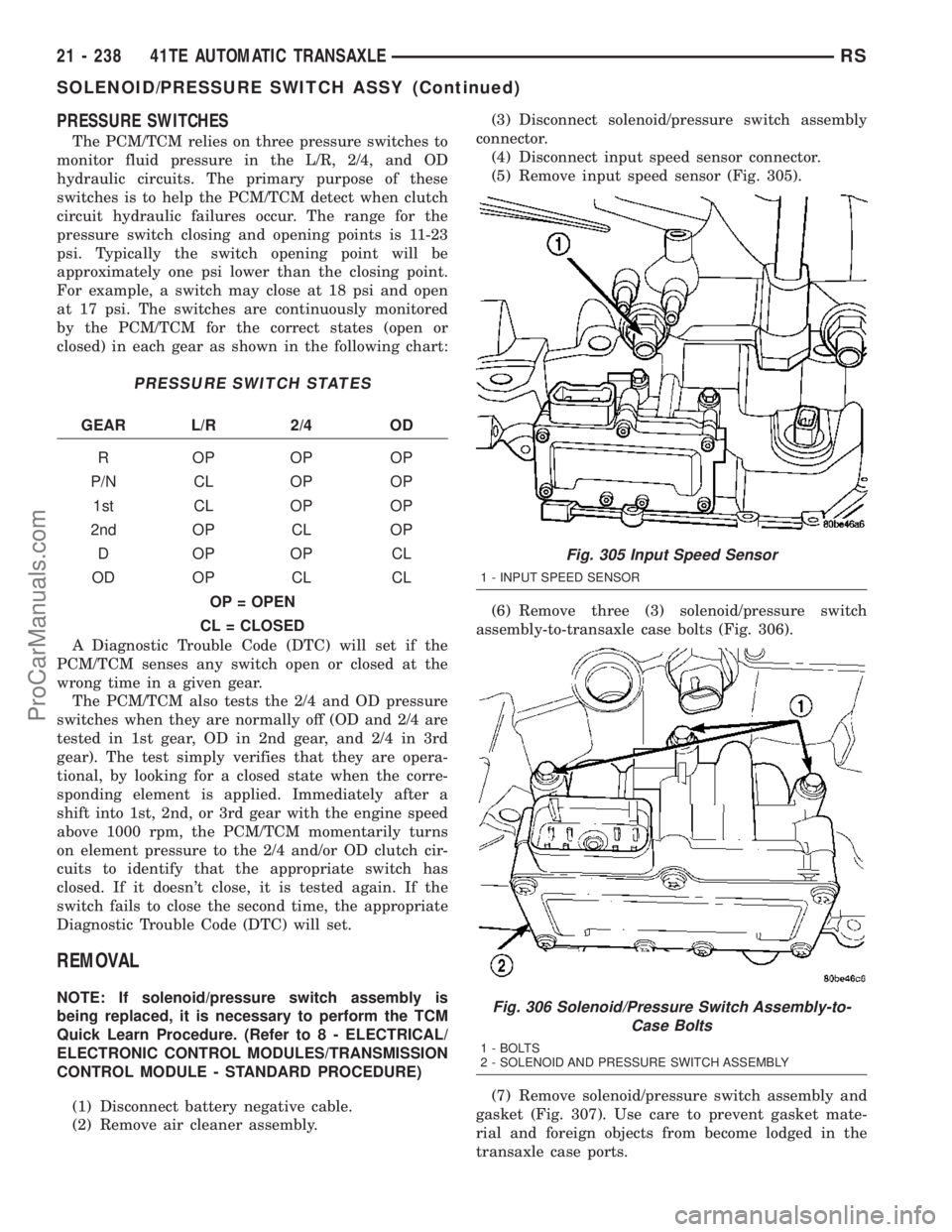
PRESSURE SWITCHES
The PCM/TCM relies on three pressure switches to
monitor fluid pressure in the L/R, 2/4, and OD
hydraulic circuits. The primary purpose of these
switches is to help the PCM/TCM detect when clutch
circuit hydraulic failures occur. The range for the
pressure switch closing and opening points is 11-23
psi. Typically the switch opening point will be
approximately one psi lower than the closing point.
For example, a switch may close at 18 psi and open
at 17 psi. The switches are continuously monitored
by the PCM/TCM for the correct states (open or
closed) in each gear as shown in the following chart:
PRESSURE SWITCH STATES
GEAR L/R 2/4 OD
ROPOPOP
P/N CL OP OP
1st CL OP OP
2nd OP CL OP
DOPOPCL
OD OP CL CL
OP = OPEN
CL = CLOSED
A Diagnostic Trouble Code (DTC) will set if the
PCM/TCM senses any switch open or closed at the
wrong time in a given gear.
The PCM/TCM also tests the 2/4 and OD pressure
switches when they are normally off (OD and 2/4 are
tested in 1st gear, OD in 2nd gear, and 2/4 in 3rd
gear). The test simply verifies that they are opera-
tional, by looking for a closed state when the corre-
sponding element is applied. Immediately after a
shift into 1st, 2nd, or 3rd gear with the engine speed
above 1000 rpm, the PCM/TCM momentarily turns
on element pressure to the 2/4 and/or OD clutch cir-
cuits to identify that the appropriate switch has
closed. If it doesn't close, it is tested again. If the
switch fails to close the second time, the appropriate
Diagnostic Trouble Code (DTC) will set.
REMOVAL
NOTE: If solenoid/pressure switch assembly is
being replaced, it is necessary to perform the TCM
Quick Learn Procedure. (Refer to 8 - ELECTRICAL/
ELECTRONIC CONTROL MODULES/TRANSMISSION
CONTROL MODULE - STANDARD PROCEDURE)
(1) Disconnect battery negative cable.
(2) Remove air cleaner assembly.(3) Disconnect solenoid/pressure switch assembly
connector.
(4) Disconnect input speed sensor connector.
(5) Remove input speed sensor (Fig. 305).
(6) Remove three (3) solenoid/pressure switch
assembly-to-transaxle case bolts (Fig. 306).
(7) Remove solenoid/pressure switch assembly and
gasket (Fig. 307). Use care to prevent gasket mate-
rial and foreign objects from become lodged in the
transaxle case ports.
Fig. 305 Input Speed Sensor
1 - INPUT SPEED SENSOR
Fig. 306 Solenoid/Pressure Switch Assembly-to-
Case Bolts
1 - BOLTS
2 - SOLENOID AND PRESSURE SWITCH ASSEMBLY
21 - 238 41TE AUTOMATIC TRANSAXLERS
SOLENOID/PRESSURE SWITCH ASSY (Continued)
ProCarManuals.com
Page 1686 of 2177
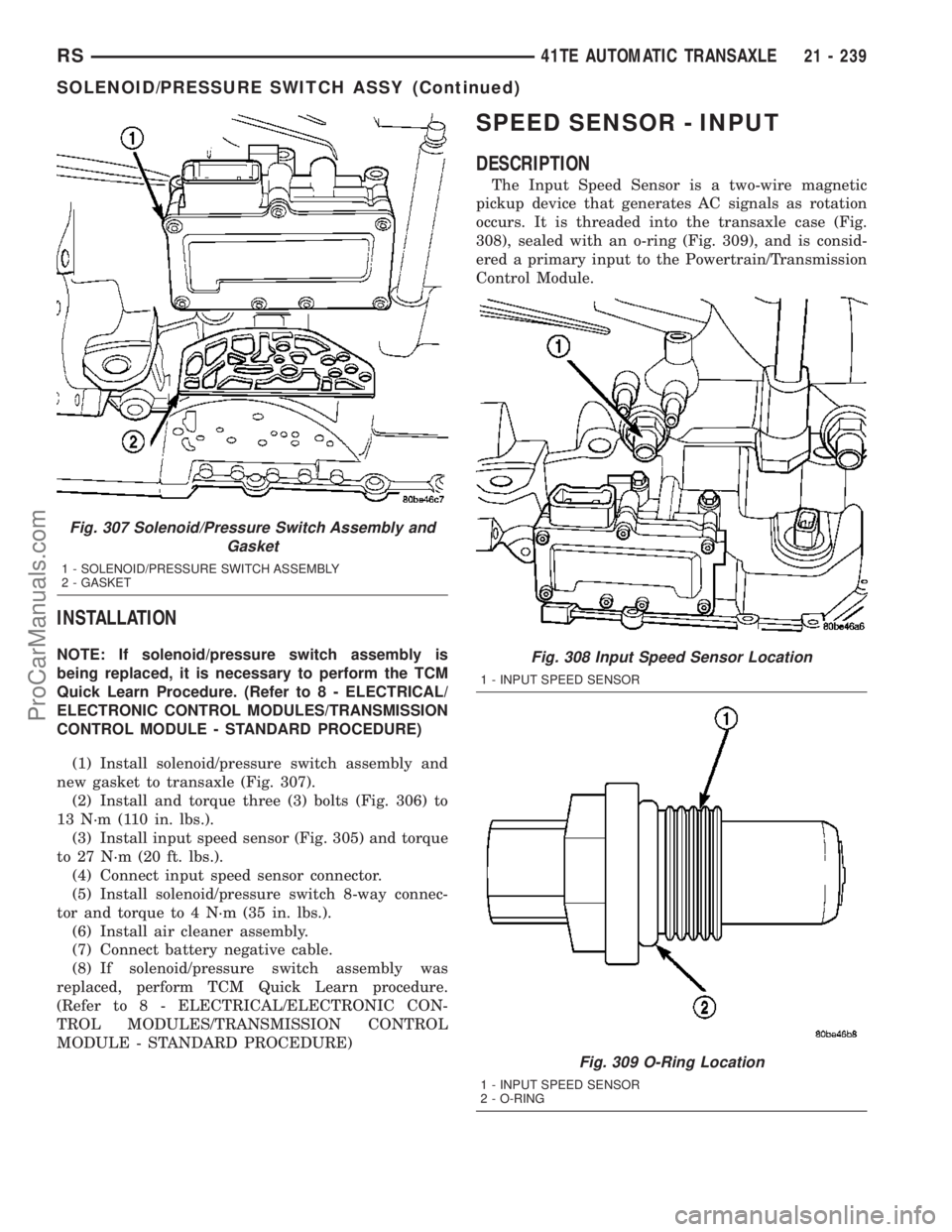
INSTALLATION
NOTE: If solenoid/pressure switch assembly is
being replaced, it is necessary to perform the TCM
Quick Learn Procedure. (Refer to 8 - ELECTRICAL/
ELECTRONIC CONTROL MODULES/TRANSMISSION
CONTROL MODULE - STANDARD PROCEDURE)
(1) Install solenoid/pressure switch assembly and
new gasket to transaxle (Fig. 307).
(2) Install and torque three (3) bolts (Fig. 306) to
13 N´m (110 in. lbs.).
(3) Install input speed sensor (Fig. 305) and torque
to 27 N´m (20 ft. lbs.).
(4) Connect input speed sensor connector.
(5) Install solenoid/pressure switch 8-way connec-
tor and torque to 4 N´m (35 in. lbs.).
(6) Install air cleaner assembly.
(7) Connect battery negative cable.
(8) If solenoid/pressure switch assembly was
replaced, perform TCM Quick Learn procedure.
(Refer to 8 - ELECTRICAL/ELECTRONIC CON-
TROL MODULES/TRANSMISSION CONTROL
MODULE - STANDARD PROCEDURE)
SPEED SENSOR - INPUT
DESCRIPTION
The Input Speed Sensor is a two-wire magnetic
pickup device that generates AC signals as rotation
occurs. It is threaded into the transaxle case (Fig.
308), sealed with an o-ring (Fig. 309), and is consid-
ered a primary input to the Powertrain/Transmission
Control Module.
Fig. 307 Solenoid/Pressure Switch Assembly and
Gasket
1 - SOLENOID/PRESSURE SWITCH ASSEMBLY
2 - GASKET
Fig. 308 Input Speed Sensor Location
1 - INPUT SPEED SENSOR
Fig. 309 O-Ring Location
1 - INPUT SPEED SENSOR
2 - O-RING
RS41TE AUTOMATIC TRANSAXLE21 - 239
SOLENOID/PRESSURE SWITCH ASSY (Continued)
ProCarManuals.com
Page 1698 of 2177
MANUAL VALVE
The manual valve is operated by the mechanical
shift linkage. Its primary responsibility is to send
line pressure to the appropriate hydraulic circuits
and solenoids. The valve has three operating ranges
or positions.
CONVERTER CLUTCH SWITCH VALVE
The main responsibility of the converter clutch
switch valve is to control hydraulic pressure applied
to the front (off) side of the converter clutch piston.
Line pressure from the regulator valve is fed to the
torque converter regulator valve, where it passes
through the valve, and is slightly regulated. The
pressure is then directed to the converter clutch
switch valve and to the front side of the converter
clutch piston. This pressure pushes the piston back
and disengages the converter clutch.
CONVERTER CLUTCH CONTROL VALVE
The converter clutch control valve controls the
back (on) side of the torque converter clutch. When
the PCM/TCM energizes or modulates the LR/CC
solenoid to apply the converter clutch piston, both
the converter clutch control valve and the converter
control valve move, allowing pressure to be applied to
the back side of the clutch.
T/C REGULATOR VALVE
The torque converter regulator valve slightly regu-
lates the flow of fluid to the torque converter.
LOW/REVERSE SWITCH VALVE
The low/reverse clutch is applied from different
sources, depending on whether low (1st) gear or
reverse is selected. The low/reverse switch valve
alternates positions depending on from which direc-
tion fluid pressure is applied. By design, when the
valve is shifted by fluid pressure from one channel,
the opposing channel is blocked. The switch valve
alienates the possibility of a sticking ball check, thus
providing consistent application of the low/reverse
clutch under all operating conditions.
REMOVAL
NOTE: If valve body is replaced or reconditioned,
the TCM Quick Learn Procedure must be per-
formed. (Refer to 8 - ELECTRICAL/ELECTRONIC
CONTROL MODULES/TRANSMISSION CONTROL
MODULE - STANDARD PROCEDURE)(1) Disconnect battery negative cable.
(2) Disconnect gearshift cable from manual valve
lever.
(3) Remove manual valve lever from manual shaft.
(4) Raise vehicle on hoist.
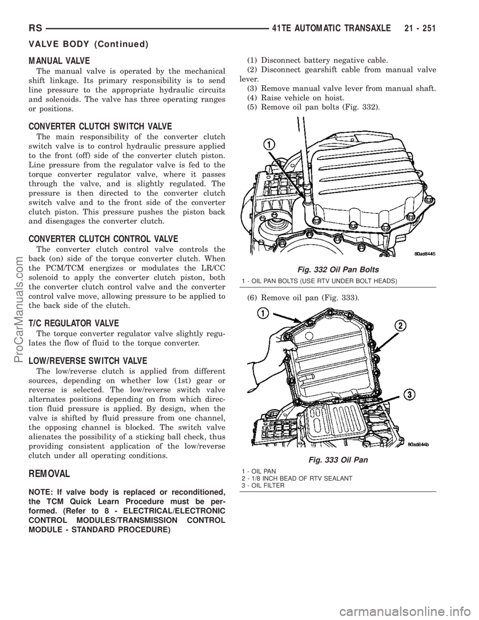
(5) Remove oil pan bolts (Fig. 332).
(6) Remove oil pan (Fig. 333).
Fig. 332 Oil Pan Bolts
1 - OIL PAN BOLTS (USE RTV UNDER BOLT HEADS)
Fig. 333 Oil Pan
1 - OIL PAN
2 - 1/8 INCH BEAD OF RTV SEALANT
3 - OIL FILTER
RS41TE AUTOMATIC TRANSAXLE21 - 251
VALVE BODY (Continued)
ProCarManuals.com
Page 1704 of 2177

(15) Remove remaining retainers as shown in (Fig.
352).(16) Remove valves and springs as shown in (Fig.
353).
NOTE: Refer to Valve Body Cleaning and Inspection
for cleaning procedures.
ASSEMBLY
NOTE: If valve body assembly is reconditioned, the
PCM/TCM Quick Learn Procedure must be per-
formed. (Refer to 8 - ELECTRICAL/ELECTRONIC
CONTROL MODULES/TRANSMISSION CONTROL
MODULE - STANDARD PROCEDURE)
(1) Install valves and springs as shown in (Fig.
353).
Fig. 353 Springs and Valves Location
1 - VALVE BODY 5 - MANUAL VALVE
2 - T/C REGULATOR VALVE 6 - CONVERTER CLUTCH SWITCH VALVE
3 - L/R SWITCH VALVE 7 - SOLENOID SWITCH VALVE
4 - CONVERTER CLUTCH CONTROL VALVE 8 - REGULATOR VALVE
Fig. 352 Valve Retainer Location
1 - RETAINER
2 - RETAINER
RS41TE AUTOMATIC TRANSAXLE21 - 257
VALVE BODY (Continued)
ProCarManuals.com