2003 CHRYSLER VOYAGER Rear window
[x] Cancel search: Rear windowPage 1798 of 2177
(32) Feed power mirror wire harness inboard
through the A-pillar.
(33) Remove the bolts attaching the instrument
panel frame to the dash panel below windshield
opening.
(34) With the help of an assistant remove the
instrument panel from vehicle. Lift the instrument
panel up off the HVAC so you won't damage the seal-
ing surface of the distribution duct.
If the instrument panel is being replaced, transfer
all parts to the new instrument panel assembly.
INSTALLATION
(1) With the help of an assistant place the instru-
ment panel into vehicle on roll down bolts. As youroll the instrument panel up, lift the instrument
panel up so the duct work does not bind or bend and
you can set it down on the HVAC housing to get the
proper seal at the distribution duct. Get one bolt
started in the dash panel.
(2) Install the left and right side A-pillar retaining
bolts. There are two 13 mm bolts and one 10 mm
bolt. The 10 mm bolts need to be installed first to
insure proper positioning of the Instrument panel in
the vehicle. Start the right side 10 mm bolt first (Fig.
6).
(3) Feed power mirror wire harness outboard
through the A-pillar.
(4) Install both the left and right power mirrors:
(a) Connect the wire connector and install the
mirror onto the vehicle.
(b) Install the three torx retaining screws.
(c) Using a firm push, snap the mirror trim
cover into place.
(5) Connect the two front window defroster grid
wire connectors. One on each side of vehicle.
(6) Tighten the right side roll down bolt.
(7) Install the right end cover. Position over retain-
ing slots and firmly snap into place.
(8) Connect the right side wire connectors to the
HVAC behind the glove box area and the two
antenna connectors behind the glove box hinge.
(9) Install the bolts attaching the instrument
panel frame to the dash panel below windshield
opening.
(10) Install the instrument panel top cover. Slide
the front edge of the top cover toward dash panel,
and firmly snap down the rear edge of the to cover to
engage clips.
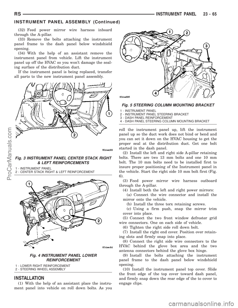
Fig. 3 INSTRUMENT PANEL CENTER STACK RIGHT
& LEFT REINFORCEMENTS
1 - INSTRUMENT PANEL
2 - CENTER STACK RIGHT & LEFT REINFORCEMENT
Fig. 4 INSTRUMENT PANEL LOWER
REINFORCEMENT
1 - LOWER RIGHT REINFORCEMENT
2 - STEERING WHEEL ASSEMBLY
Fig. 5 STEERING COLUMN MOUNTING BRACKET
1 - INSTRUMENT PANEL
2 - INSTRUMENT PANEL STEERING BRACKET
3 - DASH PANEL REINFORCEMENT
4 - DASH PANEL STEERING COLUMN MOUNTING BRACKET
RSINSTRUMENT PANEL23-65
INSTRUMENT PANEL ASSEMBLY (Continued)
ProCarManuals.com
Page 1838 of 2177
STATIONARY GLASS
TABLE OF CONTENTS
page page
WINDSHIELD
DESCRIPTION........................105
WARNING
WINDSHIELD SAFETY PRECAUTIONS....105
REMOVAL............................105
INSTALLATION........................106
SLIDING DOOR GLASS
REMOVAL............................107INSTALLATION........................107
QUARTER WINDOW
REMOVAL............................108
INSTALLATION........................108
REAR DOOR GLASS
REMOVAL............................108
INSTALLATION........................108
WINDSHIELD
DESCRIPTION
The windshield is attached to the window frame
with urethane adhesive. The urethane adhesive is
applied cold and seals the surface area between the
window opening and the glass. The primer adheres
the urethane adhesive to the windshield.
It is difficult to salvage a windshield during the
removal operation. The windshield is part of the
structural support for the roof. The urethane bonding
used to secure the windshield to the fence is difficult
to cut or clean from any surface. If the moldings are
set in urethane, it would also be unlikely they could
be salvaged. Before removing the windshield, check
the availability of the windshield and moldings from
the parts supplier.
WARNING
WINDSHIELD SAFETY PRECAUTIONS
WARNING: DO NOT OPERATE THE VEHICLE
WITHIN 24 HOURS OF WINDSHIELD INSTALLATION.
IT TAKES AT LEAST 24 HOURS FOR URETHANE
ADHESIVE TO CURE. IF IT IS NOT CURED, THE
WINDSHIELD MAY NOT PERFORM PROPERLY IN
AN ACCIDENT.
URETHANE ADHESIVES ARE APPLIED AS A SYS-
TEM. USE GLASS CLEANER, GLASS PREP SOL-
VENT, GLASS PRIMER, PVC (VINYL) PRIMER AND
PINCH WELD (FENCE) PRIMER PROVIDED BY THE
ADHESIVE MANUFACTURER. IF NOT, STRUCTURAL
INTEGRITY COULD BE COMPROMISED.
DAIMLERCHRYSLER DOES NOT RECOMMEND
GLASS ADHESIVE BY BRAND. TECHNICIANS
SHOULD REVIEW PRODUCT LABELS AND TECHNI-
CAL DATA SHEETS, AND USE ONLY ADHESIVESTHAT THEIR MANUFACTURES WARRANT WILL
RESTORE A VEHICLE TO THE REQUIREMENTS OF
FMVSS 212. TECHNICIANS SHOULD ALSO INSURE
THAT PRIMERS AND CLEANERS ARE COMPATIBLE
WITH THE PARTICULAR ADHESIVE USED.
BE SURE TO REFER TO THE URETHANE MANU-
FACTURER'S DIRECTIONS FOR CURING TIME
SPECIFICATIONS, AND DO NOT USE ADHESIVE
AFTER ITS EXPIRATION DATE.
VAPORS THAT ARE EMITTED FROM THE URE-
THANE ADHESIVE OR PRIMER COULD CAUSE
PERSONAL INJURY. USE THEM IN A WELL-VENTI-
LATED AREA.
SKIN CONTACT WITH URETHANE ADHESIVE
SHOULD BE AVOIDED. PERSONAL INJURY MAY
RESULT.
ALWAYS WEAR EYE AND HAND PROTECTION
WHEN WORKING WITH GLASS.
CAUTION: Protect all painted and trimmed surfaces
from coming in contact with urethane or primers.
Be careful not to damage painted surfaces when
removing moldings or cutting urethane around
windshield.
REMOVAL
WINDSHIELD REMOVAL ± EXTERIOR METHOD
The urethane adhesive holding the windshield to
the opening pinch weld (fence) can be cut using a
sharp cold knife from the exterior of the vehicle.
Using the cold knife method is effective if the wind-
shield is already broken. If the glass must be sal-
vaged, cutting the urethane adhesive from the
interior of the vehicle using a reciprocating or oscil-
lating power knife is recommended.
(1) Remove inside rear view mirror.
(2) Remove windshield wiper arms.
(3) Remove cowl cover.
RSSTATIONARY GLASS23 - 105
ProCarManuals.com
Page 1841 of 2177
QUARTER WINDOW
REMOVAL
(1) Remove C-pillar trim.
(2) Open quarter glass to vent position.
(3) Disengage quarter window retainer from vent
motor arm.
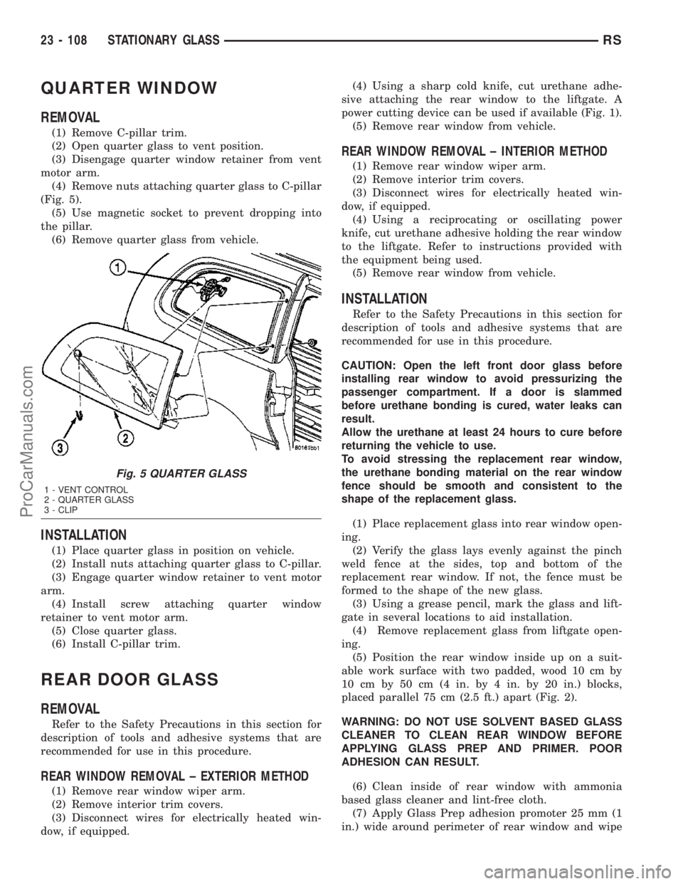
(4) Remove nuts attaching quarter glass to C-pillar
(Fig. 5).
(5) Use magnetic socket to prevent dropping into
the pillar.
(6) Remove quarter glass from vehicle.
INSTALLATION
(1) Place quarter glass in position on vehicle.
(2) Install nuts attaching quarter glass to C-pillar.
(3) Engage quarter window retainer to vent motor
arm.
(4) Install screw attaching quarter window
retainer to vent motor arm.
(5) Close quarter glass.
(6) Install C-pillar trim.
REAR DOOR GLASS
REMOVAL
Refer to the Safety Precautions in this section for
description of tools and adhesive systems that are
recommended for use in this procedure.
REAR WINDOW REMOVAL ± EXTERIOR METHOD
(1) Remove rear window wiper arm.
(2) Remove interior trim covers.
(3) Disconnect wires for electrically heated win-
dow, if equipped.(4) Using a sharp cold knife, cut urethane adhe-
sive attaching the rear window to the liftgate. A
power cutting device can be used if available (Fig. 1).
(5) Remove rear window from vehicle.
REAR WINDOW REMOVAL ± INTERIOR METHOD
(1) Remove rear window wiper arm.
(2) Remove interior trim covers.
(3) Disconnect wires for electrically heated win-
dow, if equipped.
(4) Using a reciprocating or oscillating power
knife, cut urethane adhesive holding the rear window
to the liftgate. Refer to instructions provided with
the equipment being used.
(5) Remove rear window from vehicle.
INSTALLATION
Refer to the Safety Precautions in this section for
description of tools and adhesive systems that are
recommended for use in this procedure.
CAUTION: Open the left front door glass before
installing rear window to avoid pressurizing the
passenger compartment. If a door is slammed
before urethane bonding is cured, water leaks can
result.
Allow the urethane at least 24 hours to cure before
returning the vehicle to use.
To avoid stressing the replacement rear window,
the urethane bonding material on the rear window
fence should be smooth and consistent to the
shape of the replacement glass.
(1) Place replacement glass into rear window open-
ing.
(2) Verify the glass lays evenly against the pinch
weld fence at the sides, top and bottom of the
replacement rear window. If not, the fence must be
formed to the shape of the new glass.
(3) Using a grease pencil, mark the glass and lift-
gate in several locations to aid installation.
(4) Remove replacement glass from liftgate open-
ing.
(5) Position the rear window inside up on a suit-
able work surface with two padded, wood 10 cm by
10 cm by 50 cm (4 in. by 4 in. by 20 in.) blocks,
placed parallel 75 cm (2.5 ft.) apart (Fig. 2).
WARNING: DO NOT USE SOLVENT BASED GLASS
CLEANER TO CLEAN REAR WINDOW BEFORE
APPLYING GLASS PREP AND PRIMER. POOR
ADHESION CAN RESULT.
(6) Clean inside of rear window with ammonia
based glass cleaner and lint-free cloth.
(7) Apply Glass Prep adhesion promoter 25 mm (1
in.) wide around perimeter of rear window and wipe
Fig. 5 QUARTER GLASS
1 - VENT CONTROL
2 - QUARTER GLASS
3 - CLIP
23 - 108 STATIONARY GLASSRS
ProCarManuals.com
Page 1842 of 2177
with clean/dry lint-free cloth until no streaks are vis-
ible.
(8) Apply Glass Primer 25 mm (1 in.) wide around
perimeter of rear window. Allow at least three min-
utes drying time.
(9) Apply Pinch weld Primer 19 mm (0.75 in.) wide
around the rear window fence. Allow at least three
minutes drying time.
(10) If a low viscosity urethane adhesive is used,
install compression spacers on the fence around the
rear window opening.
(11) Apply a 10 mm (0.4 in.) bead of urethane
along center line of rear window fence.
CAUTION: Be careful so that spacers do not con-
tamianate urethane bead.
(12) Apply 2 glass spacer clips to bottom edge of
glass, approximately 1.5 mm (0.6 in) inboard from
each corner.(13) With the aid of a helper, position the rear
window over the rear window opening and align the
reference marks.
(14) Slowly lower glass to rear window opening
fence. Ensure spacers on bottom edge of glass contact
sheet metal ledge. Then, push glass inward until
flush to liftgate surface.
(15) Clean excess urethane from exterior with
MopartSuper Kleen, or equivalent.
(16) Apply 150 mm (6 in.) lengths of 50 mm (2 in.)
masking tape spaced 250 mm (10 in.) apart to hold
molding in place until urethane cures.
(17) Install rear window wiper arm.
(18) Install interior trim.
(19) After urethane has cured, remove tape strips,
slide out bottom spacer clips, and then water test
rear window to verify repair.
RSSTATIONARY GLASS23 - 109
REAR DOOR GLASS (Continued)
ProCarManuals.com
Page 1852 of 2177
(3) Connect the timed sunroof assembly to a
power source and assure proper operation before
installing the sunroof assembly into the vehicle.
ADJUSTMENTS
ADJUSTMENT
CAUTION: THE IS NO ADJUSTMENT AVAILABLE
FOR A NORMALLY OPERATING SUNROOF. THIS
PROCEDURE IS USE TO SET SUNROOF MOTOR TO
SUNROOF ASSEMBLY TIMING.
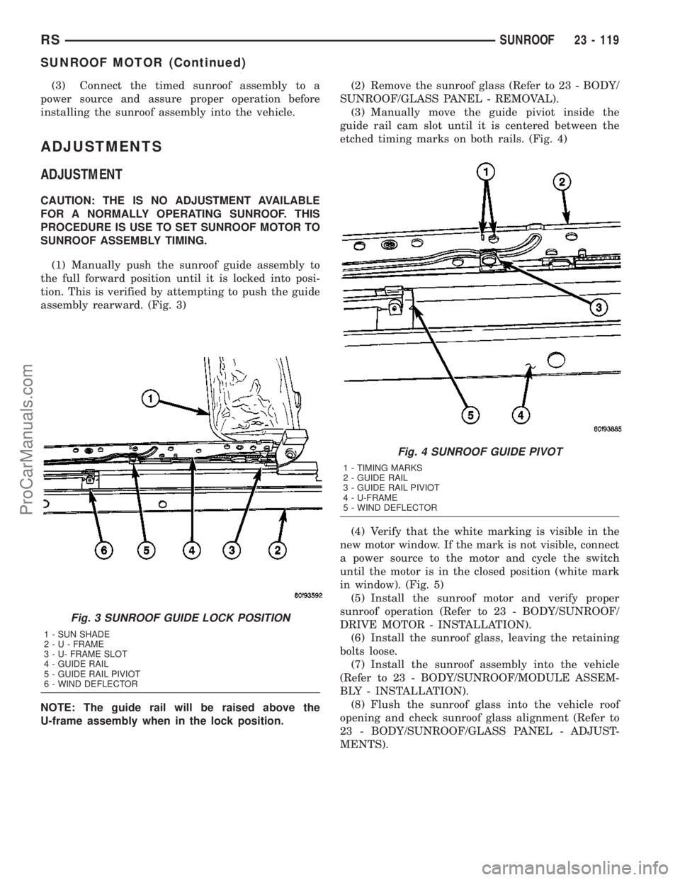
(1) Manually push the sunroof guide assembly to
the full forward position until it is locked into posi-
tion. This is verified by attempting to push the guide
assembly rearward. (Fig. 3)
NOTE: The guide rail will be raised above the
U-frame assembly when in the lock position.(2) Remove the sunroof glass (Refer to 23 - BODY/
SUNROOF/GLASS PANEL - REMOVAL).
(3) Manually move the guide piviot inside the
guide rail cam slot until it is centered between the
etched timing marks on both rails. (Fig. 4)
(4) Verify that the white marking is visible in the
new motor window. If the mark is not visible, connect
a power source to the motor and cycle the switch
until the motor is in the closed position (white mark
in window). (Fig. 5)
(5) Install the sunroof motor and verify proper
sunroof operation (Refer to 23 - BODY/SUNROOF/
DRIVE MOTOR - INSTALLATION).
(6) Install the sunroof glass, leaving the retaining
bolts loose.
(7) Install the sunroof assembly into the vehicle
(Refer to 23 - BODY/SUNROOF/MODULE ASSEM-
BLY - INSTALLATION).
(8) Flush the sunroof glass into the vehicle roof
opening and check sunroof glass alignment (Refer to
23 - BODY/SUNROOF/GLASS PANEL - ADJUST-
MENTS).
Fig. 3 SUNROOF GUIDE LOCK POSITION
1 - SUN SHADE
2-U-FRAME
3 - U- FRAME SLOT
4 - GUIDE RAIL
5 - GUIDE RAIL PIVIOT
6 - WIND DEFLECTOR
Fig. 4 SUNROOF GUIDE PIVOT
1 - TIMING MARKS
2 - GUIDE RAIL
3 - GUIDE RAIL PIVIOT
4 - U-FRAME
5 - WIND DEFLECTOR
RSSUNROOF23 - 119
SUNROOF MOTOR (Continued)
ProCarManuals.com
Page 1998 of 2177
HEATING & AIR CONDITIONING
TABLE OF CONTENTS
page page
HEATING & AIR CONDITIONING
DESCRIPTION
DESCRIPTION - SINGLE ZONE...........1
DESCRIPTION - DUAL ZONE.............1
DESCRIPTION - MANUAL THREE ZONE.....1
DESCRIPTION - AUTOMATIC
TEMPERATURE CONTROL...............2
OPERATION
OPERATION - DUAL ZONE...............3
OPERATION - MANUAL THREE ZONE......3
OPERATION - THREE ZONE ATC..........3
DIAGNOSIS AND TESTING
DIAGNOSIS AND TESTING - A/C COOL
DOWN TEST..........................4DIAGNOSIS AND TESTING - A/C
PERFORMANCE TEST..................5
DIAGNOSIS AND TESTING - HEATER
PERFORMANCE TEST..................6
SPECIFICATIONS - HEATER-A/C SYSTEM.....7
CONTROLS - FRONT......................8
CONTROLS - REAR......................29
DISTRIBUTION - FRONT...................39
DISTRIBUTION - REAR....................52
PLUMBING - FRONT.....................60
PLUMBING - REAR......................94
DIESEL SUPPLEMENTAL HEATER - DCHA -
EXPORT..............................106
HEATING & AIR
CONDITIONING
DESCRIPTION
DESCRIPTION - SINGLE ZONE
A single zone heating and air conditioning system
allows one temperature setting for the entire vehicle.
The full range of temperatures that the system can
produce are available by rotating the temperature
control located in control panel.
The control panel and integral computer is
mounted in the instrument panel.
DESCRIPTION - DUAL ZONE
A manual Dual Zone Heating and Air Conditioning
system allows completely independent side-to-side
tempeture control of the discharge air.
The control panel and integral computer is located
in the instrument panel.
The instrument panel mounted control and inte-
gral computer contains:
²a power button which allows the system to be
completely turned off. Contains an LED that illumi-
nates to show when the function is operational.
²rear window defogger on/off switch. Contains an
LED that illuminates to show when the function is
operational.
²slide controls for completely independent side-to-
side temperature control of the discharged air. The
full range of temperature that the system can pro-
duce in any mode is available on either side of thevehicle by independently positioning the slide con-
trols on the instrument panel.
²air recirculation on/off switch. The Recirculate
button contains an LED that illuminates to show
when the function is in operation.
²air conditioning on/off switch. The Snowflake
button contains an LED that illuminates to shown
when the function is in operation.
²rotary knob for fan speed selection.
²a rotary knob for mode control.
DESCRIPTION - MANUAL THREE ZONE
The fully adjustable Three-Zone front and rear
heating and air conditioning system allows interme-
diate seat passengers the ability to regulate air tem-
perature as well as fan speed. All controls are
identified by ISO graphic symbols.
FRONT CONTROL PANEL
The front control panel and integral computer is
mounted in the instrument panel.
The instrument panel mounted control and inte-
gral computer contains:
²a power button which allows the system to be
completely turned off.
²rear window defogger on/off switch.
²slide controls for completely independent side-to-
side temperature control of the discharge air. The full
range of temperature that the system can produce in
any mode is available on either side of the vehicle by
independently positioning the slide controls on the
instrument panel.
RSHEATING & AIR CONDITIONING24-1
ProCarManuals.com
Page 1999 of 2177
²air recirculation button. The Recirculate button
contains an LED that illuminates to show when the
function is in operation.
²an air conditioning button that allows the com-
pressor to be turned on/off. The Snowflake button
contains an LED that illuminates to shown when the
function is in operation.
²rotary knobs for front and rear fan speed selec-
tion.
²a rotary knob for mode control.
REAR CONTROL PANEL
A rear control panel centrally mounted on the
headliner has a rotary adjustment for temperature
and fan speed control of the rear unit by intermedi-
ate seat passengers when the front control rear knob
is set to the rear position.
DESCRIPTION - AUTOMATIC TEMPERATURE
CONTROL
The Automatic Temperature Control (ATC) allows
occupants to select a comfort temperature, which is
the perceived temperature level not the actual pas-
senger compartment air temperature.
The Automatic Temperature Control system
includes a dust and odor air filter. The filter element
is the same size as the air conditioning evaporator to
ensure ample capacity. A door at the base of the
heater and air conditioning housing below the glove
box provides easy access to the filter element.
The ATC computer utilizes integrated circuitry and
information carried on the Programmable Communi-
cations Interface (PCI) data bus network to monitor
many sensors and switch inputs throughout the vehi-
cle. In response to those inputs, the internal circuitry
and programming of the ATC computer allow it to
control electronic functions and features of the ATC
system. The inputs to the ATC computer are:
²Vehicle Speed/Engine RPM± The ATC com-
puter monitors engine RPM, vehicle speed and Man-
ifold Absolute Pressure information from the PCM.
²Coolant Temperature± ATC computer moni-
tors Coolant temperature received from the PCM and
converts it to degrees Fahrenheit.
²Ambient Temperature± ATC computer moni-
tors Ambient temperature from the Compass Mini
Trip Computer (CMTC) and converts it to degrees
Fahrenheit.
²Engine Miscellaneous Sensor Status±ATC
computer monitors A/C disable information from the
PCM.
²Refrigerant Pressure± ATC computer moni-
tors Barometric Pressure, Intake Air Temperature,
High Side Pressure and Methanol Content as broad-
cast by the PCM.²Door Ajar Status± The ATC computer moni-
tors Driver Front Door, Passenger Front Door, Left
Rear Door, Right Rear Door and Liftgate ajar infor-
mation, as identified by the Body Control Module
(BCM), to determine if all in-car temperatures should
be maintained.
²Dimming± The ATC computer monitors dim-
ming status from the BCM to determine the required
level of brightness and will dim accordingly.
²Vehicle Odometer± The ATC computer moni-
tors the vehicle odometer information from the BCM
to prevent flashing the VF tube icons if the manual
motor calibration or manual cool down tests have
failed. Flashing of the display icons will cease when
the vehicle odometer is greater than 3 miles.
²English/Metric± The ATC computer monitors
the English/Metric information broadcast by the
CMTC. The set temp displays for both the front and
rear control heads will be set accordingly.
²Vehicle Identification Number± The ATC
computer monitors the last eight characters of the
VIN broadcast by the PCM and compares it to the
information stored in EEPROM. If it is different, the
new number will be stored over the old one and a
motor calibration shall be initiated.
²A/C System Information± The ATC computer
will send a message for Evaporator Temperature too
Low, Fan Blower Relay status, Evaporator Sensor
Failure, Rear Window Defogger Relay and A/C Select.
FRONT CONTROL PANEL
The front control panel and integral computer is
mounted in the instrument panel.
The instrument panel mounted control and inte-
gral computer contains:
²A power button which allows the system to be
completely turned off. The display is blank when the
system is off.
²Three rocker switches that select comfort tem-
peratures from 15É to 30É C (59É to 85É F), which are
shown in the vacuum-fluorescent digital control dis-
play. If the set temp is 59 and the down button is
pressed, the set temp value will become 55 but the
display will show LO. If the set temp is 85 and the
up button is pressed, the set temp value will become
90 but the display will show HIGH. Temperatures
can be displayed in either metric or Fahrenheit,
which is controlled from the overhead console.
²A rocker switch that selects a cool-down rate.
LO-AUTO or HI-AUTO are displayed when the sys-
tem is in automatic operation.
²A defroster button which turns on the defroster
independently during full automatic control. A
defroster symbol illuminates in the display when the
button is pressed.
24 - 2 HEATING & AIR CONDITIONINGRS
HEATING & AIR CONDITIONING (Continued)
ProCarManuals.com
Page 2000 of 2177
²Air recirculation button. A Recirculation symbol
appears in the display when the button is pressed, or
when the system exceeds 80 percent circulated air
under automatic control due to high air conditioning
demand.
²Rear window defogger on/off switch. A graphic
symbol shows when the defroster is on.
²An air conditioning button that allows the com-
pressor to be turned off. A Snowflake symbol is illu-
minated when air conditioning is on, whether under
manual or automatic control.
²Rotary knob for front fan speed selection can
override the automatic controls. LEDs surrounding
the knob show the current setting.
²Rotary knob for control of the Rear system.
²A rotary knob for mode control can override the
automatic controls. LEDs surrounding the knob show
the current setting.
²Computer logic remembers the settings of the
controls when the ignition is turned off and retains
those settings after a restart. If the system is off
when the ignition is turned off it will be off when the
engine is restarted, etc.
²Computer logic provides variable air recircula-
tion under high temperature and humidity condi-
tions. Because recirculation is generally accompanied
by increased fan noise, the proportion of recirculated
to outside air gradually approaches full recirculation
over a broad temperature range.
²Computer logic enables additional heat for diesel
equipped vehicles via a supplemental diesel heater.
REAR CONTROL PANEL
A rear control panel centrally mounted on the
headliner includes a vacuum-flourescent digital dis-
play, a rocker control for temperature and rotary con-
trols for adjustment of mode and fan speed control of
the rear unit by intermediate seat passengers.
OPERATION
OPERATION - DUAL ZONE
²The mode control knob enables continously vari-
able proportioning of air flow between modes but has
detents adjacent to each icon.
²The blower control provides five separate speeds.
²When the fan is off, the HVAC computer closes
the recirculation door to prevent outside air from
entering the passenger compartment.
²Interior air may be recirculated to speed up
heating or cooling in all modes except defrost and
mix by pressing the Recirculate button on the control
panel.
²To reduce humidity for rapid defogging the A/C
compressor runs automatically in modes from ªmix'to full defrost when outside temperatures are above
freezing.
²Air conditioning is available in any mode by
pressing the snowflake, A/C on/off, button.
OPERATION - MANUAL THREE ZONE
FRONT CONTROL PANEL
²Primary control of the rear compartment unit is
on the instrument panel. This control allows the
driver to set the rear compartment fan speed, to turn
the rear unit off, or to give control to the intermedi-
ate seat occupants by switching to the REAR posi-
tion. When the rear unit is controlled from the
instrument panel, rear air temperature is based on
the driver-side temperature control position, and the
mode (floor or overhead air) is based on the front
control's mode position.
²The mode control knob enables continously vari-
able proportioning of air flow between modes but has
detents adjacent to each icon.
²The blower control provides five separate speeds
and Off. When the fan is off, the HVAC computer
closes the recirculation door to prevent outside air
from entering the passenger compartment.
²Interior air may be recirculated to speed up
heating or cooling in all modes exccept defrost and
mix by pressing the Recirculate button on the control
panel.
²To reduce humidity for rapid defogging the A/C
compressor runs automatically in modes from ªmix'
to full defrost when outside temperatures are above
freezing.
²Air conditioning is available in any mode by
pressing the snowflake, A/C on/off, button.
REAR CONTROL PANEL
With the rear control active, temperature selection
dictates indirectly the mode (floor or overhead air) of
the rear unit: a low temperature setting directs flow
to the overhead outlets and a high temperature set-
ting to the floor.
OPERATION - THREE ZONE ATC
Comfort temperature or perceived temperature is
affected by air flow, sun impinging on exposed skin,
etc. The air temperature may be higher or lower than
the comfort temperature. Two infrared sensors, in the
instrument panel center stack i measure the temper-
ature of the occupants to determine their comfort
level relative to the selected comfort temperature.
The HVAC computer in the control module adjusts
the air flow rate and temperature to maintain the
customer-perceived comfort temperature. The air
temperature in the passenger compartment at any
time may be slightly higher or lower than the com-
RSHEATING & AIR CONDITIONING24-3
HEATING & AIR CONDITIONING (Continued)
ProCarManuals.com