2003 CHRYSLER VOYAGER oil temperature
[x] Cancel search: oil temperaturePage 1055 of 2177
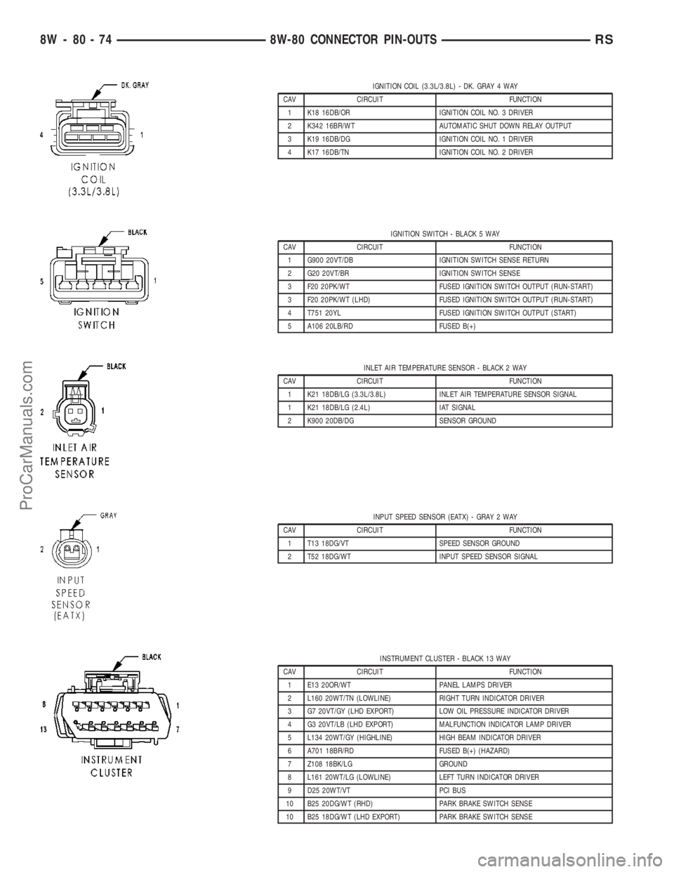
IGNITION COIL (3.3L/3.8L) - DK. GRAY 4 WAY
CAV CIRCUIT FUNCTION
1 K18 16DB/OR IGNITION COIL NO. 3 DRIVER
2 K342 16BR/WT AUTOMATIC SHUT DOWN RELAY OUTPUT
3 K19 16DB/DG IGNITION COIL NO. 1 DRIVER
4 K17 16DB/TN IGNITION COIL NO. 2 DRIVER
IGNITION SWITCH - BLACK 5 WAY
CAV CIRCUIT FUNCTION
1 G900 20VT/DB IGNITION SWITCH SENSE RETURN
2 G20 20VT/BR IGNITION SWITCH SENSE
3 F20 20PK/WT FUSED IGNITION SWITCH OUTPUT (RUN-START)
3 F20 20PK/WT (LHD) FUSED IGNITION SWITCH OUTPUT (RUN-START)
4 T751 20YL FUSED IGNITION SWITCH OUTPUT (START)
5 A106 20LB/RD FUSED B(+)
INLET AIR TEMPERATURE SENSOR - BLACK 2 WAY
CAV CIRCUIT FUNCTION
1 K21 18DB/LG (3.3L/3.8L) INLET AIR TEMPERATURE SENSOR SIGNAL
1 K21 18DB/LG (2.4L) IAT SIGNAL
2 K900 20DB/DG SENSOR GROUND
INPUT SPEED SENSOR (EATX) - GRAY 2 WAY
CAV CIRCUIT FUNCTION
1 T13 18DG/VT SPEED SENSOR GROUND
2 T52 18DG/WT INPUT SPEED SENSOR SIGNAL
INSTRUMENT CLUSTER - BLACK 13 WAY
CAV CIRCUIT FUNCTION
1 E13 20OR/WT PANEL LAMPS DRIVER
2 L160 20WT/TN (LOWLINE) RIGHT TURN INDICATOR DRIVER
3 G7 20VT/GY (LHD EXPORT) LOW OIL PRESSURE INDICATOR DRIVER
4 G3 20VT/LB (LHD EXPORT) MALFUNCTION INDICATOR LAMP DRIVER
5 L134 20WT/GY (HIGHLINE) HIGH BEAM INDICATOR DRIVER
6 A701 18BR/RD FUSED B(+) (HAZARD)
7 Z108 18BK/LG GROUND
8 L161 20WT/LG (LOWLINE) LEFT TURN INDICATOR DRIVER
9 D25 20WT/VT PCI BUS
10 B25 20DG/WT (RHD) PARK BRAKE SWITCH SENSE
10 B25 18DG/WT (LHD EXPORT) PARK BRAKE SWITCH SENSE
8W - 80 - 74 8W-80 CONNECTOR PIN-OUTSRS
ProCarManuals.com
Page 1087 of 2177
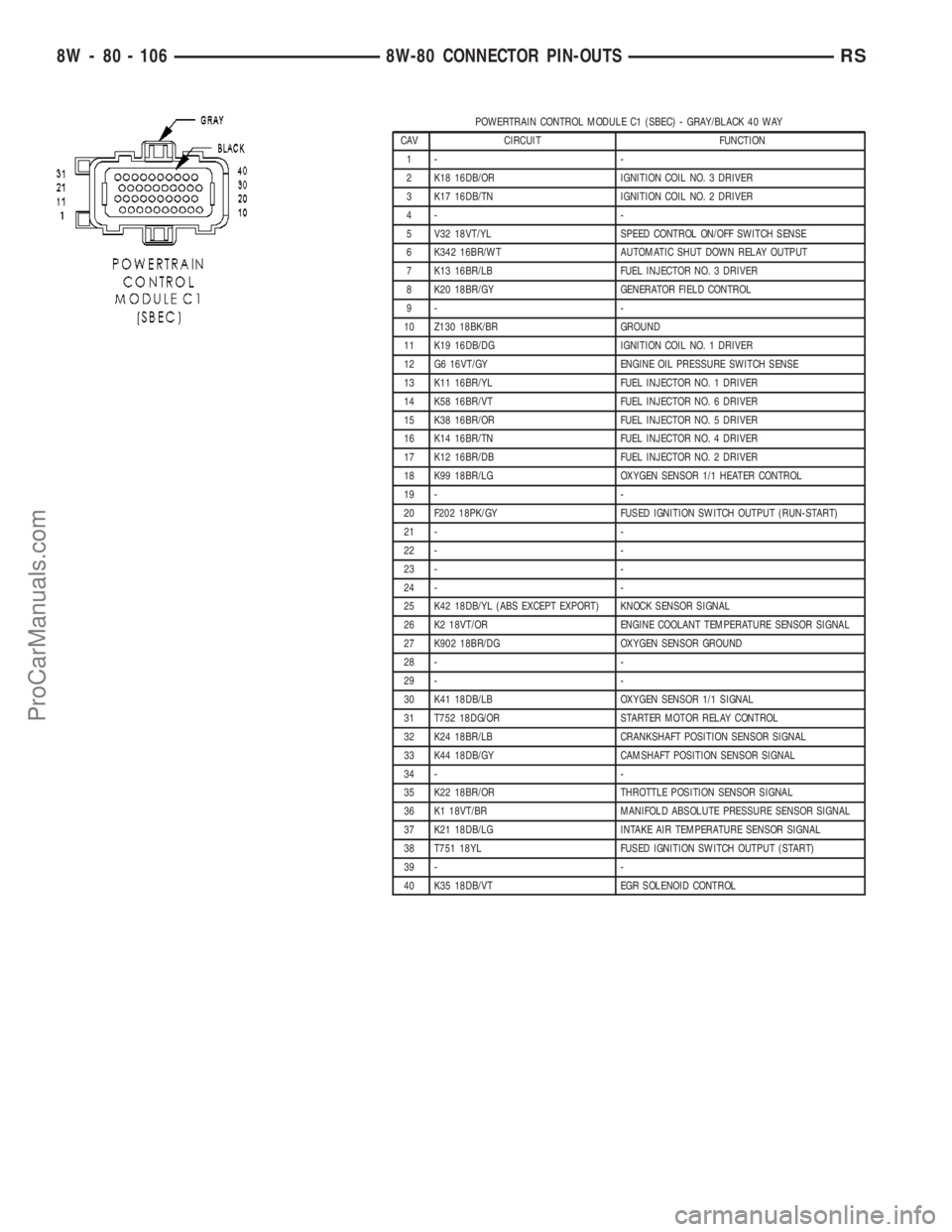
POWERTRAIN CONTROL MODULE C1 (SBEC) - GRAY/BLACK 40 WAY
CAV CIRCUIT FUNCTION
1- -
2 K18 16DB/OR IGNITION COIL NO. 3 DRIVER
3 K17 16DB/TN IGNITION COIL NO. 2 DRIVER
4- -
5 V32 18VT/YL SPEED CONTROL ON/OFF SWITCH SENSE
6 K342 16BR/WT AUTOMATIC SHUT DOWN RELAY OUTPUT
7 K13 16BR/LB FUEL INJECTOR NO. 3 DRIVER
8 K20 18BR/GY GENERATOR FIELD CONTROL
9- -
10 Z130 18BK/BR GROUND
11 K19 16DB/DG IGNITION COIL NO. 1 DRIVER
12 G6 16VT/GY ENGINE OIL PRESSURE SWITCH SENSE
13 K11 16BR/YL FUEL INJECTOR NO. 1 DRIVER
14 K58 16BR/VT FUEL INJECTOR NO. 6 DRIVER
15 K38 16BR/OR FUEL INJECTOR NO. 5 DRIVER
16 K14 16BR/TN FUEL INJECTOR NO. 4 DRIVER
17 K12 16BR/DB FUEL INJECTOR NO. 2 DRIVER
18 K99 18BR/LG OXYGEN SENSOR 1/1 HEATER CONTROL
19 - -
20 F202 18PK/GY FUSED IGNITION SWITCH OUTPUT (RUN-START)
21 - -
22 - -
23 - -
24 - -
25 K42 18DB/YL (ABS EXCEPT EXPORT) KNOCK SENSOR SIGNAL
26 K2 18VT/OR ENGINE COOLANT TEMPERATURE SENSOR SIGNAL
27 K902 18BR/DG OXYGEN SENSOR GROUND
28 - -
29 - -
30 K41 18DB/LB OXYGEN SENSOR 1/1 SIGNAL
31 T752 18DG/OR STARTER MOTOR RELAY CONTROL
32 K24 18BR/LB CRANKSHAFT POSITION SENSOR SIGNAL
33 K44 18DB/GY CAMSHAFT POSITION SENSOR SIGNAL
34 - -
35 K22 18BR/OR THROTTLE POSITION SENSOR SIGNAL
36 K1 18VT/BR MANIFOLD ABSOLUTE PRESSURE SENSOR SIGNAL
37 K21 18DB/LG INTAKE AIR TEMPERATURE SENSOR SIGNAL
38 T751 18YL FUSED IGNITION SWITCH OUTPUT (START)
39 - -
40 K35 18DB/VT EGR SOLENOID CONTROL
8W - 80 - 106 8W-80 CONNECTOR PIN-OUTSRS
ProCarManuals.com
Page 1120 of 2177
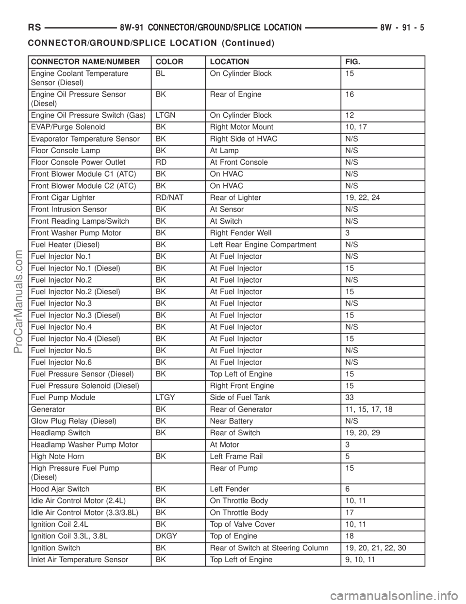
CONNECTOR NAME/NUMBER COLOR LOCATION FIG.
Engine Coolant Temperature
Sensor (Diesel)BL On Cylinder Block 15
Engine Oil Pressure Sensor
(Diesel)BK Rear of Engine 16
Engine Oil Pressure Switch (Gas) LTGN On Cylinder Block 12
EVAP/Purge Solenoid BK Right Motor Mount 10, 17
Evaporator Temperature Sensor BK Right Side of HVAC N/S
Floor Console Lamp BK At Lamp N/S
Floor Console Power Outlet RD At Front Console N/S
Front Blower Module C1 (ATC) BK On HVAC N/S
Front Blower Module C2 (ATC) BK On HVAC N/S
Front Cigar Lighter RD/NAT Rear of Lighter 19, 22, 24
Front Intrusion Sensor BK At Sensor N/S
Front Reading Lamps/Switch BK At Switch N/S
Front Washer Pump Motor BK Right Fender Well 3
Fuel Heater (Diesel) BK Left Rear Engine Compartment N/S
Fuel Injector No.1 BK At Fuel Injector N/S
Fuel Injector No.1 (Diesel) BK At Fuel Injector 15
Fuel Injector No.2 BK At Fuel Injector N/S
Fuel Injector No.2 (Diesel) BK At Fuel Injector 15
Fuel Injector No.3 BK At Fuel Injector N/S
Fuel Injector No.3 (Diesel) BK At Fuel Injector 15
Fuel Injector No.4 BK At Fuel Injector N/S
Fuel Injector No.4 (Diesel) BK At Fuel Injector 15
Fuel Injector No.5 BK At Fuel Injector N/S
Fuel Injector No.6 BK At Fuel Injector N/S
Fuel Pressure Sensor (Diesel) BK Top Left of Engine 15
Fuel Pressure Solenoid (Diesel) Right Front Engine 15
Fuel Pump Module LTGY Side of Fuel Tank 33
Generator BK Rear of Generator 11, 15, 17, 18
Glow Plug Relay (Diesel) BK Near Battery N/S
Headlamp Switch BK Rear of Switch 19, 20, 29
Headlamp Washer Pump Motor At Motor 3
High Note Horn BK Left Frame Rail 5
High Pressure Fuel Pump
(Diesel)Rear of Pump 15
Hood Ajar Switch BK Left Fender 6
Idle Air Control Motor (2.4L) BK On Throttle Body 10, 11
Idle Air Control Motor (3.3/3.8L) BK On Throttle Body 17
Ignition Coil 2.4L BK Top of Valve Cover 10, 11
Ignition Coil 3.3L, 3.8L DKGY Top of Engine 18
Ignition Switch BK Rear of Switch at Steering Column 19, 20, 21, 22, 30
Inlet Air Temperature Sensor BK Top Left of Engine 9, 10, 11
RS8W-91 CONNECTOR/GROUND/SPLICE LOCATION8W-91-5
CONNECTOR/GROUND/SPLICE LOCATION (Continued)
ProCarManuals.com
Page 1185 of 2177
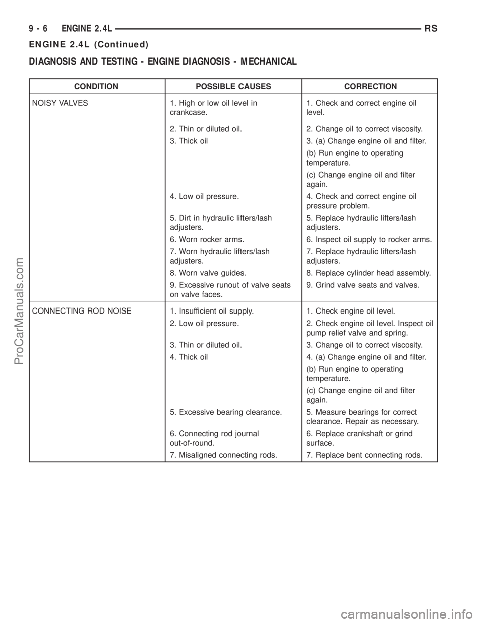
DIAGNOSIS AND TESTING - ENGINE DIAGNOSIS - MECHANICAL
CONDITION POSSIBLE CAUSES CORRECTION
NOISY VALVES 1. High or low oil level in
crankcase.1. Check and correct engine oil
level.
2. Thin or diluted oil. 2. Change oil to correct viscosity.
3. Thick oil 3. (a) Change engine oil and filter.
(b) Run engine to operating
temperature.
(c) Change engine oil and filter
again.
4. Low oil pressure. 4. Check and correct engine oil
pressure problem.
5. Dirt in hydraulic lifters/lash
adjusters.5. Replace hydraulic lifters/lash
adjusters.
6. Worn rocker arms. 6. Inspect oil supply to rocker arms.
7. Worn hydraulic lifters/lash
adjusters.7. Replace hydraulic lifters/lash
adjusters.
8. Worn valve guides. 8. Replace cylinder head assembly.
9. Excessive runout of valve seats
on valve faces.9. Grind valve seats and valves.
CONNECTING ROD NOISE 1. Insufficient oil supply. 1. Check engine oil level.
2. Low oil pressure. 2. Check engine oil level. Inspect oil
pump relief valve and spring.
3. Thin or diluted oil. 3. Change oil to correct viscosity.
4. Thick oil 4. (a) Change engine oil and filter.
(b) Run engine to operating
temperature.
(c) Change engine oil and filter
again.
5. Excessive bearing clearance. 5. Measure bearings for correct
clearance. Repair as necessary.
6. Connecting rod journal
out-of-round.6. Replace crankshaft or grind
surface.
7. Misaligned connecting rods. 7. Replace bent connecting rods.
9 - 6 ENGINE 2.4LRS
ENGINE 2.4L (Continued)
ProCarManuals.com
Page 1186 of 2177
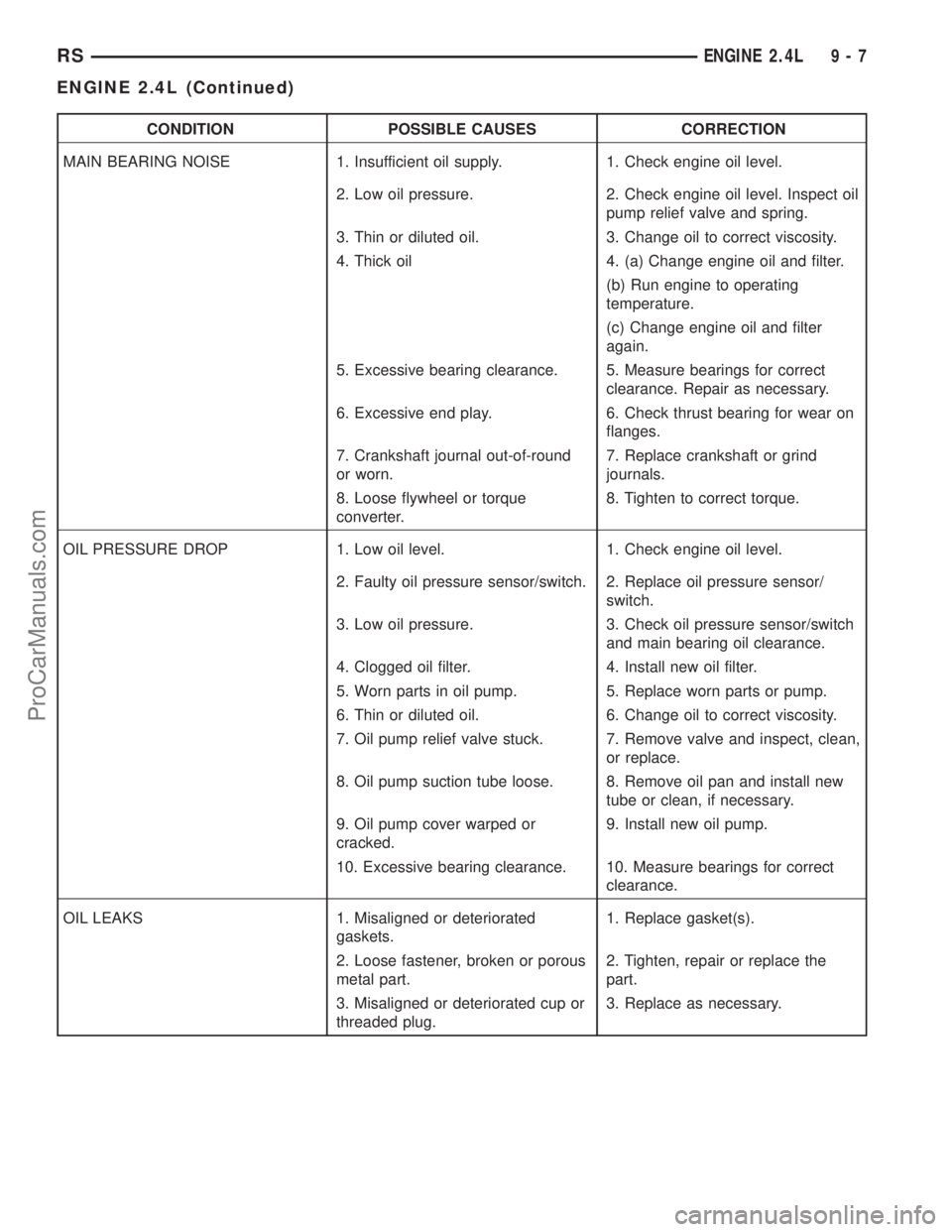
CONDITION POSSIBLE CAUSES CORRECTION
MAIN BEARING NOISE 1. Insufficient oil supply. 1. Check engine oil level.
2. Low oil pressure. 2. Check engine oil level. Inspect oil
pump relief valve and spring.
3. Thin or diluted oil. 3. Change oil to correct viscosity.
4. Thick oil 4. (a) Change engine oil and filter.
(b) Run engine to operating
temperature.
(c) Change engine oil and filter
again.
5. Excessive bearing clearance. 5. Measure bearings for correct
clearance. Repair as necessary.
6. Excessive end play. 6. Check thrust bearing for wear on
flanges.
7. Crankshaft journal out-of-round
or worn.7. Replace crankshaft or grind
journals.
8. Loose flywheel or torque
converter.8. Tighten to correct torque.
OIL PRESSURE DROP 1. Low oil level. 1. Check engine oil level.
2. Faulty oil pressure sensor/switch. 2. Replace oil pressure sensor/
switch.
3. Low oil pressure. 3. Check oil pressure sensor/switch
and main bearing oil clearance.
4. Clogged oil filter. 4. Install new oil filter.
5. Worn parts in oil pump. 5. Replace worn parts or pump.
6. Thin or diluted oil. 6. Change oil to correct viscosity.
7. Oil pump relief valve stuck. 7. Remove valve and inspect, clean,
or replace.
8. Oil pump suction tube loose. 8. Remove oil pan and install new
tube or clean, if necessary.
9. Oil pump cover warped or
cracked.9. Install new oil pump.
10. Excessive bearing clearance. 10. Measure bearings for correct
clearance.
OIL LEAKS 1. Misaligned or deteriorated
gaskets.1. Replace gasket(s).
2. Loose fastener, broken or porous
metal part.2. Tighten, repair or replace the
part.
3. Misaligned or deteriorated cup or
threaded plug.3. Replace as necessary.
RSENGINE 2.4L9-7
ENGINE 2.4L (Continued)
ProCarManuals.com
Page 1188 of 2177
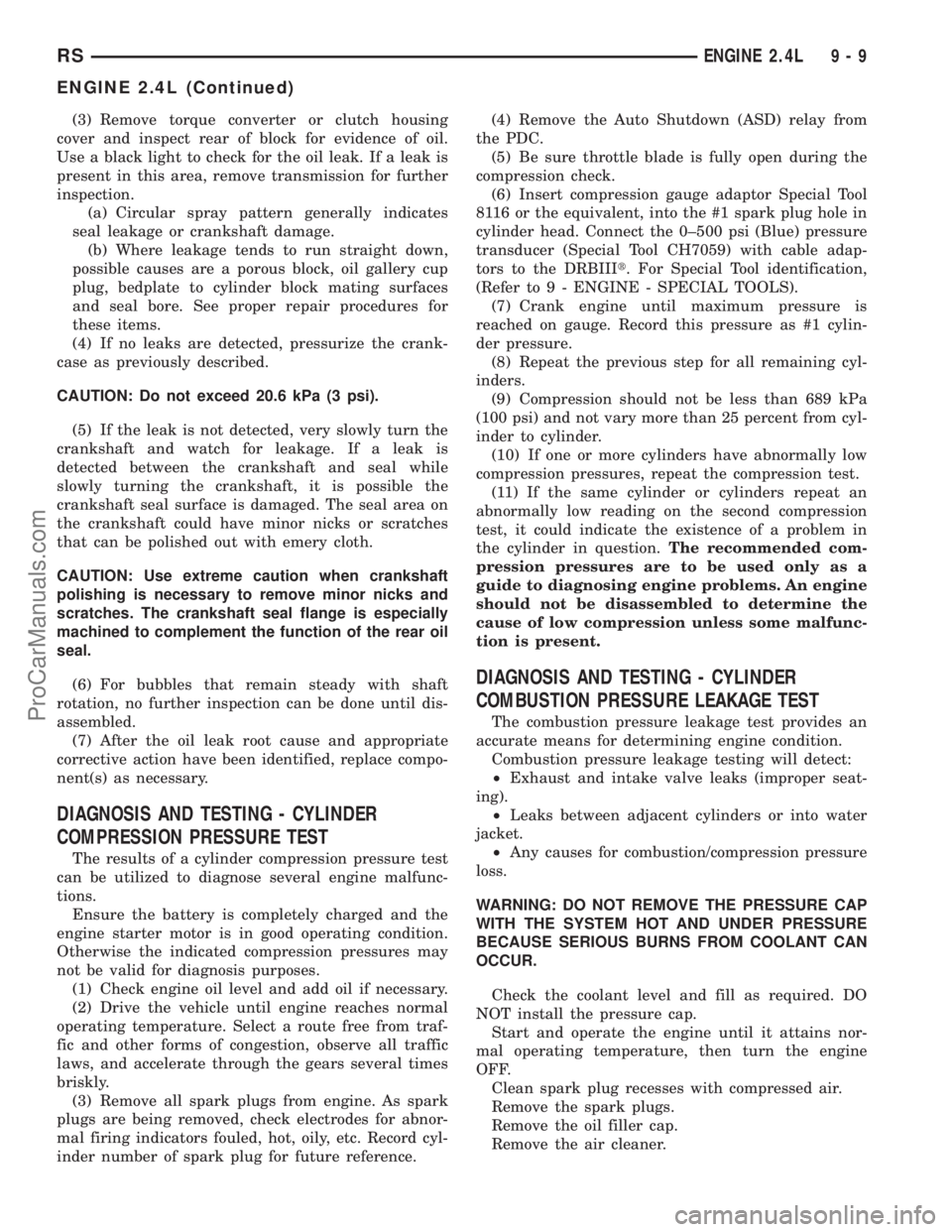
(3) Remove torque converter or clutch housing
cover and inspect rear of block for evidence of oil.
Use a black light to check for the oil leak. If a leak is
present in this area, remove transmission for further
inspection.
(a) Circular spray pattern generally indicates
seal leakage or crankshaft damage.
(b) Where leakage tends to run straight down,
possible causes are a porous block, oil gallery cup
plug, bedplate to cylinder block mating surfaces
and seal bore. See proper repair procedures for
these items.
(4) If no leaks are detected, pressurize the crank-
case as previously described.
CAUTION: Do not exceed 20.6 kPa (3 psi).
(5) If the leak is not detected, very slowly turn the
crankshaft and watch for leakage. If a leak is
detected between the crankshaft and seal while
slowly turning the crankshaft, it is possible the
crankshaft seal surface is damaged. The seal area on
the crankshaft could have minor nicks or scratches
that can be polished out with emery cloth.
CAUTION: Use extreme caution when crankshaft
polishing is necessary to remove minor nicks and
scratches. The crankshaft seal flange is especially
machined to complement the function of the rear oil
seal.
(6) For bubbles that remain steady with shaft
rotation, no further inspection can be done until dis-
assembled.
(7) After the oil leak root cause and appropriate
corrective action have been identified, replace compo-
nent(s) as necessary.
DIAGNOSIS AND TESTING - CYLINDER
COMPRESSION PRESSURE TEST
The results of a cylinder compression pressure test
can be utilized to diagnose several engine malfunc-
tions.
Ensure the battery is completely charged and the
engine starter motor is in good operating condition.
Otherwise the indicated compression pressures may
not be valid for diagnosis purposes.
(1) Check engine oil level and add oil if necessary.
(2) Drive the vehicle until engine reaches normal
operating temperature. Select a route free from traf-
fic and other forms of congestion, observe all traffic
laws, and accelerate through the gears several times
briskly.
(3) Remove all spark plugs from engine. As spark
plugs are being removed, check electrodes for abnor-
mal firing indicators fouled, hot, oily, etc. Record cyl-
inder number of spark plug for future reference.(4) Remove the Auto Shutdown (ASD) relay from
the PDC.
(5) Be sure throttle blade is fully open during the
compression check.
(6) Insert compression gauge adaptor Special Tool
8116 or the equivalent, into the #1 spark plug hole in
cylinder head. Connect the 0±500 psi (Blue) pressure
transducer (Special Tool CH7059) with cable adap-
tors to the DRBIIIt. For Special Tool identification,
(Refer to 9 - ENGINE - SPECIAL TOOLS).
(7) Crank engine until maximum pressure is
reached on gauge. Record this pressure as #1 cylin-
der pressure.
(8) Repeat the previous step for all remaining cyl-
inders.
(9) Compression should not be less than 689 kPa
(100 psi) and not vary more than 25 percent from cyl-
inder to cylinder.
(10) If one or more cylinders have abnormally low
compression pressures, repeat the compression test.
(11) If the same cylinder or cylinders repeat an
abnormally low reading on the second compression
test, it could indicate the existence of a problem in
the cylinder in question.The recommended com-
pression pressures are to be used only as a
guide to diagnosing engine problems. An engine
should not be disassembled to determine the
cause of low compression unless some malfunc-
tion is present.
DIAGNOSIS AND TESTING - CYLINDER
COMBUSTION PRESSURE LEAKAGE TEST
The combustion pressure leakage test provides an
accurate means for determining engine condition.
Combustion pressure leakage testing will detect:
²Exhaust and intake valve leaks (improper seat-
ing).
²Leaks between adjacent cylinders or into water
jacket.
²Any causes for combustion/compression pressure
loss.
WARNING: DO NOT REMOVE THE PRESSURE CAP
WITH THE SYSTEM HOT AND UNDER PRESSURE
BECAUSE SERIOUS BURNS FROM COOLANT CAN
OCCUR.
Check the coolant level and fill as required. DO
NOT install the pressure cap.
Start and operate the engine until it attains nor-
mal operating temperature, then turn the engine
OFF.
Clean spark plug recesses with compressed air.
Remove the spark plugs.
Remove the oil filler cap.
Remove the air cleaner.
RSENGINE 2.4L9-9
ENGINE 2.4L (Continued)
ProCarManuals.com
Page 1203 of 2177
AIR CLEANER ELEMENT
REMOVAL
(1) Unsnap 2 clips.
(2) Lift cover and pull toward the engine and
remove cover tabs from air box.
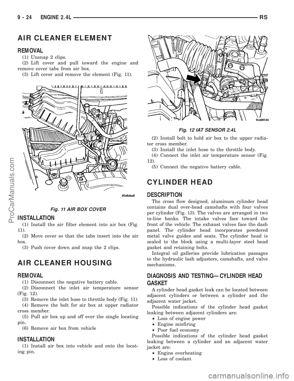
(3) Lift cover and remove the element (Fig. 11).
INSTALLATION
(1) Install the air filter element into air box (Fig.
11).
(2) Move cover so that the tabs insert into the air
box.
(3) Push cover down and snap the 2 clips.
AIR CLEANER HOUSING
REMOVAL
(1) Disconnect the negative battery cable.
(2) Disconnect the inlet air temperature sensor
(Fig. 12).
(3) Remove the inlet hose to throttle body (Fig. 11).
(4) Remove the bolt for air box at upper radiator
cross member.
(5) Pull air box up and off over the single locating
pin.
(6) Remove air box from vehicle
INSTALLATION
(1) Install air box into vehicle and onto the locat-
ing pin.(2) Install bolt to hold air box to the upper radia-
tor cross member.
(3) Install the inlet hose to the throttle body.
(4) Connect the inlet air temperature sensor (Fig.
12).
(5) Connect the negative battery cable.
CYLINDER HEAD
DESCRIPTION
The cross flow designed, aluminum cylinder head
contains dual over-head camshafts with four valves
per cylinder (Fig. 13). The valves are arranged in two
in-line banks. The intake valves face toward the
front of the vehicle. The exhaust valves face the dash
panel. The cylinder head incorporates powdered
metal valve guides and seats. The cylinder head is
sealed to the block using a multi-layer steel head
gasket and retaining bolts.
Integral oil galleries provide lubrication passages
to the hydraulic lash adjusters, camshafts, and valve
mechanisms.
DIAGNOSIS AND TESTINGÐCYLINDER HEAD
GASKET
A cylinder head gasket leak can be located between
adjacent cylinders or between a cylinder and the
adjacent water jacket.
Possible indications of the cylinder head gasket
leaking between adjacent cylinders are:
²Loss of engine power
²Engine misfiring
²Poor fuel economy
Possible indications of the cylinder head gasket
leaking between a cylinder and an adjacent water
jacket are:
²Engine overheating
²Loss of coolant
Fig. 11 AIR BOX COVER
Fig. 12 IAT SENSOR 2.4L
9 - 24 ENGINE 2.4LRS
ProCarManuals.com
Page 1213 of 2177
HYDRAULIC LASH
ADJUSTERS
DIAGNOSIS AND TESTING - HYDRAULIC LASH
ADJUSTER NOISE DIAGNOSIS
A tappet-like noise may be produced from several
items. Check the following items.
(1) Engine oil level too high or too low. This may
cause aerated oil to enter the adjusters and cause
them to be spongy.
(2) Insufficient running time after rebuilding cylin-
der head. Low speed running up to 1 hour may be
required.
(3) During this time, turn engine off and let set for
a few minutes before restarting. Repeat this several
times after engine has reached normal operating
temperature.
(4) Low oil pressure.
(5) The oil restrictor (integral to the head gasket)
in the vertical oil passage to the cylinder head is
plugged with debris.
(6) Air ingested into oil due to broken or cracked
oil pump pick up.
(7) Worn valve guides.
(8) Rocker arm ears contacting valve spring
retainer.
(9) Rocker arm loose, adjuster stuck or at maxi-
mum extension and still leaves lash in the system.
(10) Faulty lash adjuster.
²Check lash adjusters for sponginess while
installed in cylinder head. Depress part of rocker
arm over adjuster. Normal adjusters should feel very
firm. Spongy adjusters can be bottomed out easily.
²Remove suspected lash adjusters, and replace as
necessary.
REMOVAL
NOTE: This procedure is for in-vehicle service with
camshafts installed.
(1) Remove cylinder head cover. (Refer to 9 -
ENGINE/CYLINDER HEAD/CYLINDER HEAD
COVER(S) - REMOVAL)
(2) Remove rocker arm. (Refer to 9 - ENGINE/
CYLINDER HEAD/ROCKER ARMS - REMOVAL)
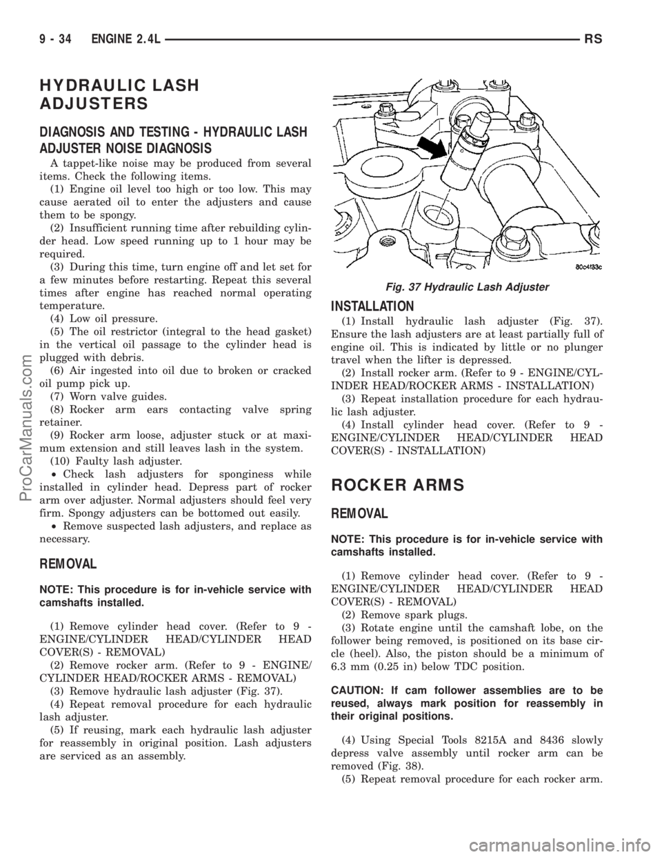
(3) Remove hydraulic lash adjuster (Fig. 37).
(4) Repeat removal procedure for each hydraulic
lash adjuster.
(5) If reusing, mark each hydraulic lash adjuster
for reassembly in original position. Lash adjusters
are serviced as an assembly.
INSTALLATION
(1) Install hydraulic lash adjuster (Fig. 37).
Ensure the lash adjusters are at least partially full of
engine oil. This is indicated by little or no plunger
travel when the lifter is depressed.
(2) Install rocker arm. (Refer to 9 - ENGINE/CYL-
INDER HEAD/ROCKER ARMS - INSTALLATION)
(3) Repeat installation procedure for each hydrau-
lic lash adjuster.
(4) Install cylinder head cover. (Refer to 9 -
ENGINE/CYLINDER HEAD/CYLINDER HEAD
COVER(S) - INSTALLATION)
ROCKER ARMS
REMOVAL
NOTE: This procedure is for in-vehicle service with
camshafts installed.
(1) Remove cylinder head cover. (Refer to 9 -
ENGINE/CYLINDER HEAD/CYLINDER HEAD
COVER(S) - REMOVAL)
(2) Remove spark plugs.
(3) Rotate engine until the camshaft lobe, on the
follower being removed, is positioned on its base cir-
cle (heel). Also, the piston should be a minimum of
6.3 mm (0.25 in) below TDC position.
CAUTION: If cam follower assemblies are to be
reused, always mark position for reassembly in
their original positions.
(4) Using Special Tools 8215A and 8436 slowly
depress valve assembly until rocker arm can be
removed (Fig. 38).
(5) Repeat removal procedure for each rocker arm.
Fig. 37 Hydraulic Lash Adjuster
9 - 34 ENGINE 2.4LRS
ProCarManuals.com