2003 CHRYSLER VOYAGER hood release
[x] Cancel search: hood releasePage 1793 of 2177
INSTALLATION
(1) Place hood in position on vehicle. With assis-
tance from a helper at the opposite side of the vehicle
to support the hood, install bottom bolts attaching
hood to hinge finger tight.
(2) Install top bolts attaching hood to hinge finger
tight.
(3) Position bolts at marks and tighten. Tighten
bolts to 13.5 N´m (120 in. lbs.) torque. The hood
should be aligned to 4 mm (0.160 in.) gap to the front
fenders and flush across the top surfaces along fend-
ers.
(4) Verify hood operation and alignment.
LATCH
REMOVAL
(1) Release hood latch and open hood.
(2) Remove bolts attaching hood latch to radiator
closure panel crossmember (Fig. 3).
(3) Remove hood latch from crossmember.
(4) Disconnect hood release cable from hood latch
(Fig. 4).
(5) Remove hood latch from vehicle.
INSTALLATION
(1) Position hood latch on vehicle.
(2) Connect hood release cable from hood latch.
(3) Position hood latch on crossmember.
(4) Align hood latch by placing latch over net
pierced tabs. If alignment is required, flatten or
grind tabs.
(5) Verify hood operation and alignment. Adjust as
necessary.(6) Tighten attaching bolts to 13.5 N´m (10 ft. lbs.)
torque.
LATCH RELEASE CABLE
REMOVAL
(1) Remove hood latch.
(2) Disengage cable end from hood latch locking
mechanism.
(3) Slide cable case end sideways in keyhole slot of
hood latch while pinching barb on cable case closed.
(4) Remove cable from latch (Fig. 4).
(5) Remove hood release handle from instrument
panel.
(6) Disengage rubber grommet cable insulator
from hole in dash panel.
(7) Attach a suitable length of mechanic's wire to
latch end of cable to assist cable installation.
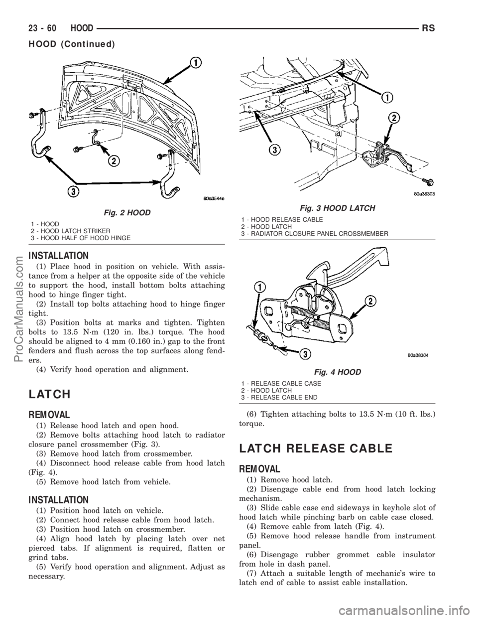
Fig. 2 HOOD
1 - HOOD
2 - HOOD LATCH STRIKER
3 - HOOD HALF OF HOOD HINGE
Fig. 3 HOOD LATCH
1 - HOOD RELEASE CABLE
2 - HOOD LATCH
3 - RADIATOR CLOSURE PANEL CROSSMEMBER
Fig. 4 HOOD
1 - RELEASE CABLE CASE
2 - HOOD LATCH
3 - RELEASE CABLE END
23 - 60 HOODRS
HOOD (Continued)
ProCarManuals.com
Page 1794 of 2177
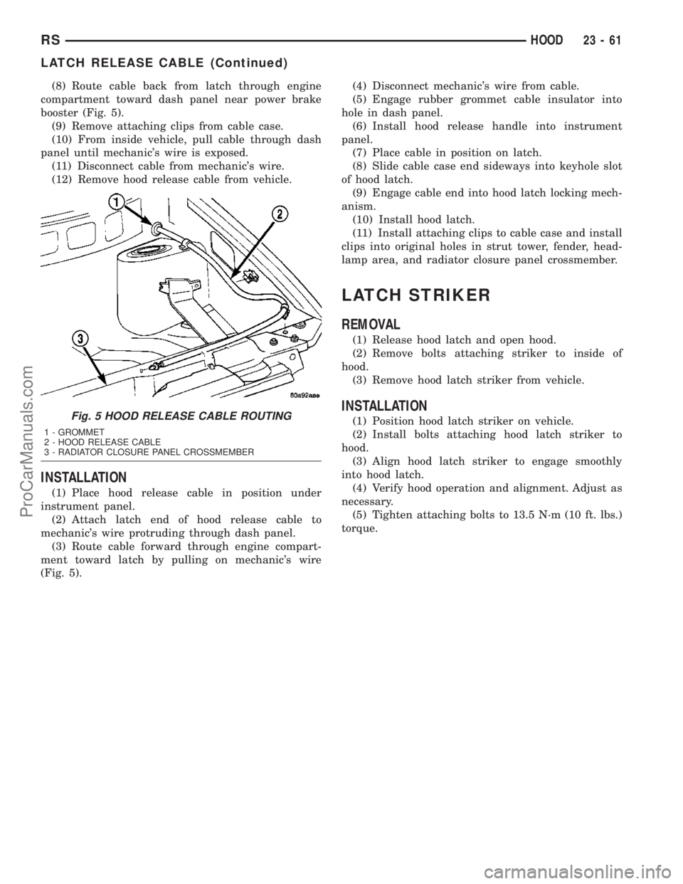
(8) Route cable back from latch through engine
compartment toward dash panel near power brake
booster (Fig. 5).
(9) Remove attaching clips from cable case.
(10) From inside vehicle, pull cable through dash
panel until mechanic's wire is exposed.
(11) Disconnect cable from mechanic's wire.
(12) Remove hood release cable from vehicle.
INSTALLATION
(1) Place hood release cable in position under
instrument panel.
(2) Attach latch end of hood release cable to
mechanic's wire protruding through dash panel.
(3) Route cable forward through engine compart-
ment toward latch by pulling on mechanic's wire
(Fig. 5).(4) Disconnect mechanic's wire from cable.
(5) Engage rubber grommet cable insulator into
hole in dash panel.
(6) Install hood release handle into instrument
panel.
(7) Place cable in position on latch.
(8) Slide cable case end sideways into keyhole slot
of hood latch.
(9) Engage cable end into hood latch locking mech-
anism.
(10) Install hood latch.
(11) Install attaching clips to cable case and install
clips into original holes in strut tower, fender, head-
lamp area, and radiator closure panel crossmember.
LATCH STRIKER
REMOVAL
(1) Release hood latch and open hood.
(2) Remove bolts attaching striker to inside of
hood.
(3) Remove hood latch striker from vehicle.
INSTALLATION
(1) Position hood latch striker on vehicle.
(2) Install bolts attaching hood latch striker to
hood.
(3) Align hood latch striker to engage smoothly
into hood latch.
(4) Verify hood operation and alignment. Adjust as
necessary.
(5) Tighten attaching bolts to 13.5 N´m (10 ft. lbs.)
torque.Fig. 5 HOOD RELEASE CABLE ROUTING
1 - GROMMET
2 - HOOD RELEASE CABLE
3 - RADIATOR CLOSURE PANEL CROSSMEMBER
RSHOOD23-61
LATCH RELEASE CABLE (Continued)
ProCarManuals.com
Page 1797 of 2177
GLOVE BOX LATCH STRIKER
REMOVAL
(1) Open glove box door.
(2) Remove screws holding lock striker to instru-
ment panel.
(3) Remove glove box latch striker.
INSTALLATION
(1) Install the glove box latch striker.
(2) Install the screws holding latch striker to
instrument panel.
(3) Close glove box door.
INSTRUMENT PANEL
ASSEMBLY
REMOVAL
(1) Disconnect and isolate the battery negative
cable.
(2) Remove the lower console:
(a) Remove six retaining screws.
(b) Pull rearward and disconnect the auxiliary
power outlet.
(c) Remove lower console from vehicle.
(3) Remove the bolts attaching the lower supports
to the instrument panel frame (Fig. 3).
(4) Remove the bolts attaching the lower supports
to the floor pan.
(5) Disconnect the wire connectors from the Pas-
senger Airbag.
(6) Remove the two screws to each right and left
cowl trim covers.
(7) Remove the both left and right side A-pillar
trim covers using a trim stick (special tool #C-4755)
or equivalent gently pry out on the trim covers and
remove.
(8) Remove the glove box:
(a) Push in on sides of glove box bin and lower
door.
(b) Pivot glove box downward and disengage
hinge hooks from instrument panel.
(c) Remove glove box from vehicle.
(9) Disconnect the antenna lead connector from
behind the glove box.
(10) Remove the four screws to the lower steering
column cover.
(11) Remove the eight screws to the steering col-
umn backing plate.
(12) Unclip the Data Link Connector (DLC) from
the steering column backing plate.
(13) Disconnect the left side wiring:
(a) Brake switch.
(b) Main bulkhead connector.(c) Five harness connectors.
(d) Driver airbag connector.
(14) Remove the two screws to the hood release
handle.
(15) Remove five screws to steering column back-
ing plate and remove (Refer to 23 - BODY/INSTRU-
MENT PANEL/KNEE BLOCKER - REMOVAL).
(16) Remove the two steering column shroud
retaining screws. Separate the shrouds and remove
from vehicle.
(17) Remove the screws attaching the instrument
panel reinforcement and remove (Fig. 4).
(18) Disconnect the steering column wiring. There
are seven connectors and then unclip the harness
from the column.
(19) Disconnect the Occupant Restraint Controller
(ORC) harness connector.
(20) Remove the four nuts retaining the steering
column to the dash panel steering column mounting
bracket and lower column to the floor (Fig. 5).
(21) Remove the four nuts attaching the instru-
ment panel to the brake pedal support bracket.
(22) Loosen the left side roll down bolt (Fig. 6).
(23) Remove the left side A-pillar retaining bolts.
There are two 13 mm bolts and one 10 mm bolt.
(24) If equipped with a mechanical transmission
range indicator:
(a) Remove the indicator cable loop.
(b) Remove the clip holding gear shift cable end
to the gear selector adapter.
(c) Pull the cable end from gear selector.
(d) Disconnect the clip for the indicator cable
and guide tube from the shift cable bracket and
move out of the way.
(25) Remove the instrument panel top cover. Using
a trim stick or equivalent, gently pry up on the front
edge of the top cover, pull rearward and remove from
vehicle.
(26) Disconnect the right side wire connectors from
the HVAC behind the glove box area and the two
antenna connectors behind the glove box hinge.
(27) Remove the right end cover by pulling out-
board.
(28) Remove the right side A-pillar retaining bolts.
There are two 13 mm bolts and one 10 mm bolt.
(29) Loosen the right side roll down bolt.
(30) Disconnect the two front window defroster
grid wire connectors. One on each side of vehicle.
(31) Remove both the left and right power mirrors:
(a) Using a trim stick or equivalent, gently pry
out on mirror trim cover.
(b) Open door and remove the three torx retain-
ing screws.
(c) Disconnect the wire connector and remove
mirror from the vehicle.
23 - 64 INSTRUMENT PANELRS
ProCarManuals.com
Page 1799 of 2177
(11) If equipped with a mechanical transmission
range indicator:
(a) Connect the clip for the indicator cable and
guide tube to the shift cable bracket.
(b) Install the cable end to the gear selector.
(c) Install the clip holding the gear shift cable
end to the gear selector adapter.
(d) Install the indicator cable loop.
(12) Tighten the left side roll down bolt.
(13) Install the four nuts attaching the instrument
panel to the brake pedal support bracket.
(14) Install the four nuts retaining the steering
column and lower to the floor (Fig. 5).
(15) Connect the Occupant Restraint Controller
(ORC) harness connector.
(16) Connect the steering column wiring. There
are seven connectors and then clip the harness to the
column.
(17) Install the screws attaching the instrument
panel reinforcement (Fig. 4).
(18) Connect the shrouds and install the two steer-
ing column shroud retaining screws.
(19) Install five screws to the left under column
instrument panel reinforcement brace.
(20) Install the two screws to the hood release
handle.
(21) Connect the left side wiring:
(a) Brake switch.
(b) Main bulkhead connector.(c) Five harness connectors.
(d) Driver airbag connector.
(22) Clip the Data Link Connector (DLC) to the
steering column backing plate.
(23) Install the eight screws to the steering column
backing plate.
(24) Install the four screws to the lower steering
column cover.
(25) Install the glove box:
(a) Install glove box into the vehicle. Line up the
hinges and firmly snap together.
(b) Push in on sides of glove box bin and raise
door.
(26) Install the both left and right side A-pillar
trim covers. Position trim cover over slots and firmly
snap into place.
(27) Install the two screws to each right and left
cowl trim covers.
(28) Connect the wire connectors to the Passenger
Airbag.
(29) Install the bolts attaching the lower supports
to the floor pan.
(30) Install the bolts attaching the lower supports
to the instrument panel frame (Fig. 3).
(31) Install the lower console:
(a) Install lower console to vehicle.
(b) Connect the auxiliary power outlet.
(c) Install the six retaining screws.
(32) Connect the battery negative cable.
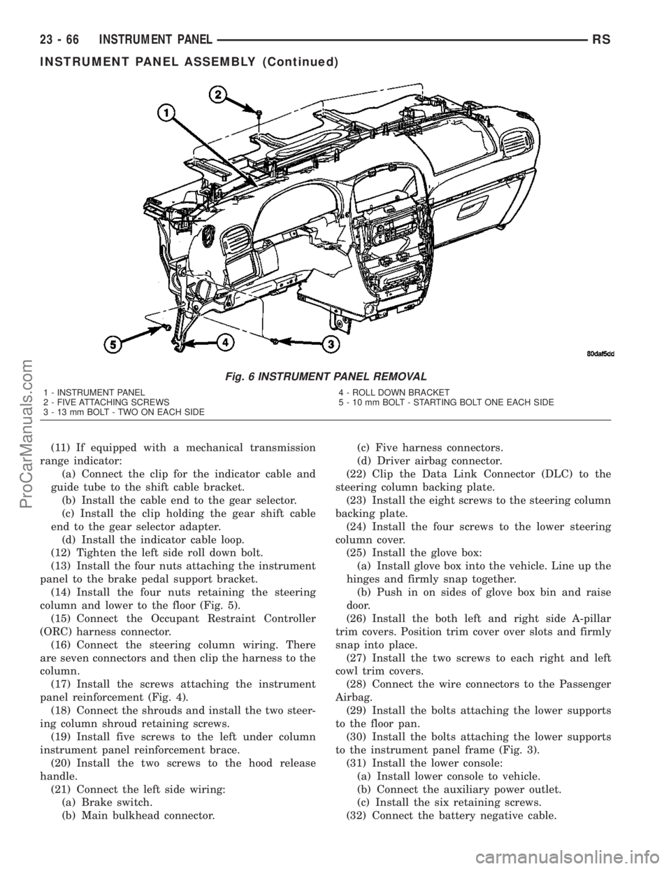
Fig. 6 INSTRUMENT PANEL REMOVAL
1 - INSTRUMENT PANEL
2 - FIVE ATTACHING SCREWS
3 - 13 mm BOLT - TWO ON EACH SIDE4 - ROLL DOWN BRACKET
5 - 10 mm BOLT - STARTING BOLT ONE EACH SIDE
23 - 66 INSTRUMENT PANELRS
INSTRUMENT PANEL ASSEMBLY (Continued)
ProCarManuals.com
Page 2085 of 2177
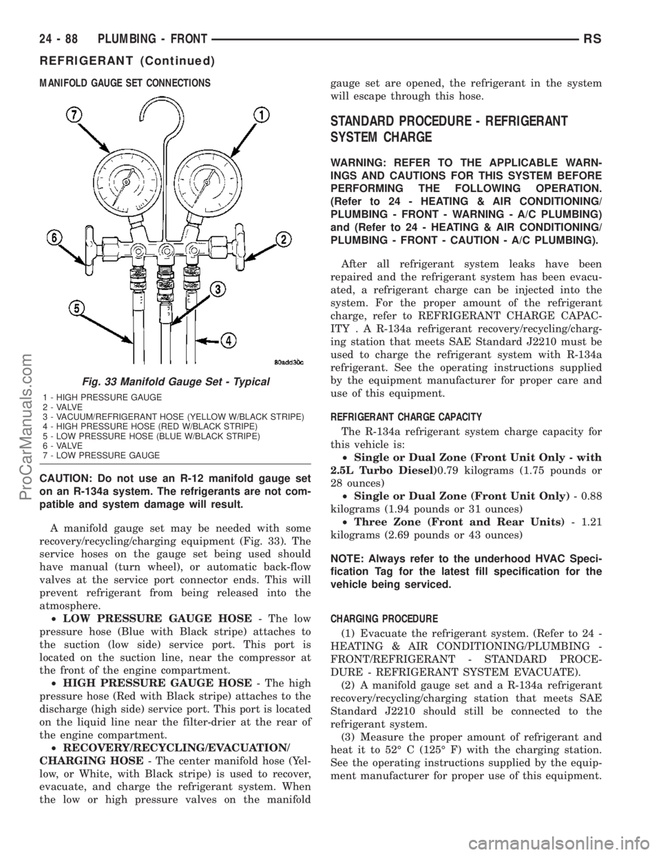
MANIFOLD GAUGE SET CONNECTIONS
CAUTION: Do not use an R-12 manifold gauge set
on an R-134a system. The refrigerants are not com-
patible and system damage will result.
A manifold gauge set may be needed with some
recovery/recycling/charging equipment (Fig. 33). The
service hoses on the gauge set being used should
have manual (turn wheel), or automatic back-flow
valves at the service port connector ends. This will
prevent refrigerant from being released into the
atmosphere.
²LOW PRESSURE GAUGE HOSE- The low
pressure hose (Blue with Black stripe) attaches to
the suction (low side) service port. This port is
located on the suction line, near the compressor at
the front of the engine compartment.
²HIGH PRESSURE GAUGE HOSE- The high
pressure hose (Red with Black stripe) attaches to the
discharge (high side) service port. This port is located
on the liquid line near the filter-drier at the rear of
the engine compartment.
²RECOVERY/RECYCLING/EVACUATION/
CHARGING HOSE- The center manifold hose (Yel-
low, or White, with Black stripe) is used to recover,
evacuate, and charge the refrigerant system. When
the low or high pressure valves on the manifoldgauge set are opened, the refrigerant in the system
will escape through this hose.
STANDARD PROCEDURE - REFRIGERANT
SYSTEM CHARGE
WARNING: REFER TO THE APPLICABLE WARN-
INGS AND CAUTIONS FOR THIS SYSTEM BEFORE
PERFORMING THE FOLLOWING OPERATION.
(Refer to 24 - HEATING & AIR CONDITIONING/
PLUMBING - FRONT - WARNING - A/C PLUMBING)
and (Refer to 24 - HEATING & AIR CONDITIONING/
PLUMBING - FRONT - CAUTION - A/C PLUMBING).
After all refrigerant system leaks have been
repaired and the refrigerant system has been evacu-
ated, a refrigerant charge can be injected into the
system. For the proper amount of the refrigerant
charge, refer to REFRIGERANT CHARGE CAPAC-
ITY . A R-134a refrigerant recovery/recycling/charg-
ing station that meets SAE Standard J2210 must be
used to charge the refrigerant system with R-134a
refrigerant. See the operating instructions supplied
by the equipment manufacturer for proper care and
use of this equipment.
REFRIGERANT CHARGE CAPACITY
The R-134a refrigerant system charge capacity for
this vehicle is:
²Single or Dual Zone (Front Unit Only - with
2.5L Turbo Diesel)0.79 kilograms (1.75 pounds or
28 ounces)
²Single or Dual Zone (Front Unit Only)- 0.88
kilograms (1.94 pounds or 31 ounces)
²Three Zone (Front and Rear Units)- 1.21
kilograms (2.69 pounds or 43 ounces)
NOTE: Always refer to the underhood HVAC Speci-
fication Tag for the latest fill specification for the
vehicle being serviced.
CHARGING PROCEDURE
(1) Evacuate the refrigerant system. (Refer to 24 -
HEATING & AIR CONDITIONING/PLUMBING -
FRONT/REFRIGERANT - STANDARD PROCE-
DURE - REFRIGERANT SYSTEM EVACUATE).
(2) A manifold gauge set and a R-134a refrigerant
recovery/recycling/charging station that meets SAE
Standard J2210 should still be connected to the
refrigerant system.
(3) Measure the proper amount of refrigerant and
heat it to 52É C (125É F) with the charging station.
See the operating instructions supplied by the equip-
ment manufacturer for proper use of this equipment.
Fig. 33 Manifold Gauge Set - Typical
1 - HIGH PRESSURE GAUGE
2 - VALVE
3 - VACUUM/REFRIGERANT HOSE (YELLOW W/BLACK STRIPE)
4 - HIGH PRESSURE HOSE (RED W/BLACK STRIPE)
5 - LOW PRESSURE HOSE (BLUE W/BLACK STRIPE)
6 - VALVE
7 - LOW PRESSURE GAUGE
24 - 88 PLUMBING - FRONTRS
REFRIGERANT (Continued)
ProCarManuals.com
Page 2140 of 2177
ABS FASTENER TORQUE,
SPECIFICATIONS......................5-79
ABSORBER - DESCRIPTION, SHOCK.......2-36
ABSORBER - INSTALLATION, SHOCK......2-38
ABSORBER - OPERATION, SHOCK........2-36
ABSORBER - REMOVAL, SHOCK..........2-36
ABSORBER (UPPER BUSHING) -
ASSEMBLY, SHOCK....................2-37
ABSORBER (UPPER BUSHING) -
DISASSEMBLY, SHOCK.................2-36
A/C COMPRESSOR - DESCRIPTION......24-63
A/C COMPRESSOR - OPERATION........24-63
A/C COOL DOWN TEST - DIAGNOSIS
AND TESTING........................24-4
A/C DISTRIBUTION DUCT -
INSTALLATION.......................24-53
A/C DISTRIBUTION DUCT - REMOVAL....24-53
A/C HEATER CONTROL - INSTALLATION....24-9
A/C HEATER CONTROL - REMOVAL.......24-9
A/C PERFORMANCE TEST - DIAGNOSIS
AND TESTING........................24-5
A/C PLUMBING - CAUTION.............24-61
A/C PLUMBING - WARNING............24-61
A/C PRESSURE TRANSDUCER -
DESCRIPTION.......................24-10
A/C PRESSURE TRANSDUCER -
DIAGNOSIS AND TESTING.............24-10
A/C PRESSURE TRANSDUCER -
INSTALLATION.......................24-11
A/C PRESSURE TRANSDUCER -
OPERATION.........................24-10
A/C PRESSURE TRANSDUCER -
REMOVAL..........................24-10
ACCELERATOR PEDAL - INSTALLATION . . . 14-24
ACCELERATOR PEDAL - REMOVAL.......14-23
ACCESSORY DRIVE BELT - DIAGNOSIS
AND TESTING.........................7-7
ACCESSORY DRIVE BELT TENSION,
SPECIFICATIONS.......................7-5
ACCESSORY RELAY - DESCRIPTION . . . 8W-97-2
ACCESSORY RELAY - DIAGNOSIS &
TESTING.........................8W-97-2
ACCESSORY RELAY - OPERATION.....8W-97-2
ACCUMULATOR - DESCRIPTION........21-188
ACCUMULATOR - OPERATION..........21-189
A/C-HEATER CONTROL - INSTALLATION . . . 24-29
A/C-HEATER CONTROL - REMOVAL......24-29
ACTUATOR - DESCRIPTION, BLEND
DOOR........................24-11,24-30
ACTUATOR - DESCRIPTION, ENGAGE.....8N-10
ACTUATOR - DESCRIPTION, LATCH......8N-14
ACTUATOR - DESCRIPTION, MODE
DOOR.............................24-24
ACTUATOR - DESCRIPTION,
RECIRCULATION DOOR................24-27
ACTUATOR - INSTALLATION, BLEND
DOOR........................24-12,24-31
ACTUATOR - INSTALLATION, ENGAGE....8N-11
ACTUATOR - INSTALLATION, LATCH.....8N-14
ACTUATOR - INSTALLATION, MODE
DOOR........................24-25,24-36
ACTUATOR - INSTALLATION,
RECIRCULATION DOOR................24-28
ACTUATOR - OPERATION, BLEND DOOR . . 24-11,
24-30
ACTUATOR - OPERATION, ENGAGE......8N-11
ACTUATOR - OPERATION, LATCH........8N-14
ACTUATOR - OPERATION, MODE DOOR . . . 24-24
ACTUATOR - OPERATION,
RECIRCULATION DOOR................24-27
ACTUATOR - REMOVAL, BLEND DOOR . . . 24-12,
24-31
ACTUATOR - REMOVAL, ENGAGE........8N-11
ACTUATOR - REMOVAL, LATCH.........8N-14
ACTUATOR - REMOVAL, MODE DOOR....24-25,
24-36
ACTUATOR - REMOVAL, RECIRCULATION
DOOR.............................24-27
ADAPTER - INSTALLATION, FRONT DISC
BRAKE CALIPER......................5-31
ADAPTER - INSTALLATION, OIL FILTER
. . . 9-139
ADAPTER - REMOVAL, FRONT DISC
BRAKE CALIPER
......................5-31
ADAPTER - REMOVAL, OIL FILTER
.......9-139
ADAPTIVE MEMORIES, OPERATION -
FUEL CORRECTION OR
................14-20
ADDING ADDITIONAL COOLANT -
STANDARD PROCEDURE
.................7-5ADDITIONAL COOLANT - STANDARD
PROCEDURE, ADDING...................7-5
ADHESIVE ATTACHED - INSTALLATION,
EXTERIOR NAME PLATES..............23-50
ADHESIVE ATTACHED - REMOVAL,
EXTERIOR NAME PLATES..............23-50
ADHESIVE LOCATIONS -
SPECIFICATIONS, STRUCTURAL........23-153
ADJUSTER-BORC-PILLAR -
INSTALLATION, SEAT BELT HEIGHT......8O-12
ADJUSTER-BORC-PILLAR -
REMOVAL, SEAT BELT HEIGHT..........8O-12
ADJUSTER - DIAGNOSIS AND TESTING,
DRUM BRAKE AUTOMATIC..............5-13
ADJUSTER - INSTALLATION, FRONT
SEAT TRACK MANUAL................23-94
ADJUSTER - INSTALLATION, FRONT
SEAT TRACK POWER.................23-94
ADJUSTER - REMOVAL, FRONT SEAT
TRACK MANUAL.....................23-94
ADJUSTER - REMOVAL, FRONT SEAT
TRACK POWER......................23-94
ADJUSTER KNOB - INSTALLATION, SEAT
BELT HEIGHT.......................8O-13
ADJUSTER KNOB - REMOVAL, SEAT
BELT HEIGHT.......................8O-13
ADJUSTER NOISE DIAGNOSIS -
DIAGNOSIS AND TESTING, HYDRAULIC
LASH...............................9-34
ADJUSTER TENSION RELEASE -
STANDARD PROCEDURE, PARKING
BRAKE AUTOMATIC....................5-58
ADJUSTER TENSION RESET -
STANDARD PROCEDURE, PARKING
BRAKE AUTOMATIC.....................5-59
ADJUSTERS - INSTALLATION,
HYDRAULIC LASH.....................9-34
ADJUSTERS - REMOVAL, HYDRAULIC
LASH...............................9-34
AERATION - DIAGNOSIS AND TESTING,
COOLING SYSTEM.....................7-3
AFTER AN AIRBAG DEPLOYMENT -
STANDARD PROCEDURE, SERVICE.......8O-3
AIR CLEANER ELEMENT - INSTALLATION . . 9-24,
9-98
AIR CLEANER ELEMENT - REMOVAL . . 9-24,9-98
AIR CLEANER HOUSING - INSTALLATION . . 9-24,
9-99
AIR CLEANER HOUSING - REMOVAL . . 9-24,9-99
AIR CONDITIONING LINES -
INSTALLATION, REAR................24-105
AIR CONDITIONING LINES - REMOVAL,
REAR.............................24-104
AIR CONTROL MOTOR - DESCRIPTION,
IDLE...............................14-28
AIR CONTROL MOTOR - INSTALLATION,
IDLE...............................14-29
AIR CONTROL MOTOR - OPERATION,
IDLE...............................14-28
AIR CONTROL MOTOR - REMOVAL, IDLE . . 14-29
AIR EXHAUSTER - DESCRIPTION, REAR
QUARTER PANEL/FENDER..............23-56
AIR EXHAUSTER - INSTALLATION, REAR
QUARTER PANEL/FENDER..............23-57
AIR EXHAUSTER - REMOVAL, REAR
QUARTER PANEL/FENDER..............23-56
AIR FILTER - DESCRIPTION............24-39
AIR FILTER - INSTALLATION............24-40
AIR FILTER - REMOVAL...............24-39
AIR GAP - STANDARD PROCEDURE,
COMPRESSOR CLUTCH...............24-17
AIR GAP, SPECIFICATIONS - WHEEL
SPEED SENSOR.......................5-79
AIR INTAKE PIPE - INSTALLATION......24-113
AIR INTAKE PIPE - REMOVAL..........24-112
AIR OUTLETS - DESCRIPTION.....24-40,24-52
AIR OUTLETS - INSTALLATION..........24-52
AIR OUTLETS - REMOVAL.............24-52
AIR PRESSURE TESTS - DIAGNOSIS
AND TESTING, CLUTCH...............21-122
AIR TEMPERATURE SENSOR -
DESCRIPTION, INLET.................14-29
AIR TEMPERATURE SENSOR -
OPERATION, INLET
...................14-29
AIRBAG - DESCRIPTION, DRIVER
........8O-5
AIRBAG - DESCRIPTION, PASSENGER
.....8O-7
AIRBAG - DESCRIPTION, SEAT
..........8O-10
AIRBAG - INSTALLATION, DRIVER
........8O-6AIRBAG - INSTALLATION, PASSENGER....8O-9
AIRBAG - OPERATION, DRIVER..........8O-5
AIRBAG - OPERATION, PASSENGER.......8O-8
AIRBAG - OPERATION, SEAT...........8O-11
AIRBAG - REMOVAL, DRIVER............8O-5
AIRBAG - REMOVAL, PASSENGER........8O-8
AIRBAG CONTROL MODULE -
DESCRIPTION, SIDE IMPACT...........8O-17
AIRBAG CONTROL MODULE -
INSTALLATION, SIDE IMPACT...........8O-17
AIRBAG CONTROL MODULE -
OPERATION, SIDE IMPACT.............8O-17
AIRBAG CONTROL MODULE - REMOVAL,
SIDE IMPACT.......................8O-17
AIRBAG DEPLOYMENT - STANDARD
PROCEDURE, SERVICE AFTER AN........8O-3
AIRBAG SYSTEM - DIAGNOSIS AND
TESTING............................8O-2
AIRBAG TRIM COVER - INSTALLATION,
DRIVER.............................8O-7
AIRBAG TRIM COVER - REMOVAL,
DRIVER.............................8O-6
AIRBAGS - STANDARD PROCEDURE,
HANDLING..........................8O-3
AJAR SWITCH - EXPORT -
INSTALLATION, HOOD.................8Q-3
AJAR SWITCH - EXPORT - REMOVAL,
HOOD..............................8Q-3
ALIGNMENT - DESCRIPTION, WHEEL......2-46
ALIGNMENT - EXPORT - STANDARD
PROCEDURE, FRONT FOG LAMP UNIT.....8L-9
ALIGNMENT - EXPORT - STANDARD
PROCEDURE, HEADLAMP UNIT.........8L-17
ALIGNMENT - STANDARD PROCEDURE,
FRONT FOG LAMP UNIT................8L-9
ALIGNMENT - STANDARD PROCEDURE,
FRONT WIPER ARM...................8R-8
ALIGNMENT - STANDARD PROCEDURE,
HEADLAMP UNIT.....................8L-17
ALIGNMENT - STANDARD PROCEDURE,
WHEEL.............................2-51
ALIGNMENT, SPECIFICATIONS - WHEEL....2-55
ALUMINUM WHEEL CARE - CLEANING . . . 22-18
AMBIENT TEMP SENSOR - DESCRIPTION . 8M-11
AMBIENT TEMP SENSOR - OPERATION . . 8M-11
AMBIENT TEMPERATURE SENSOR -
DIAGNOSIS AND TESTING.............8M-12
AMBIENT TEMPERATURE SENSOR
CIRCUIT - DIAGNOSIS AND TESTING....8M-12
AN AIRBAG DEPLOYMENT - STANDARD
PROCEDURE, SERVICE AFTER...........8O-3
ANTENNA - EXPORT - DESCRIPTION,
QUARTER GLASS INTEGRAL............8A-9
ANTENNA - EXPORT - DIAGNOSIS AND
TESTING, QUARTER GLASS INTEGRAL....8A-9
ANTENNA - EXPORT - OPERATION,
QUARTER GLASS INTEGRAL............8A-9
ANTENNA BODY AND CABLE -
DESCRIPTION........................8A-4
ANTENNA BODY AND CABLE -
DIAGNOSIS AND TESTING..............8A-4
ANTENNA BODY AND CABLE -
INSTALLATION.......................8A-6
ANTENNA BODY AND CABLE -
OPERATION..........................8A-4
ANTENNA BODY AND CABLE - REMOVAL . . 8A-5
ANTENNA CABLE - INSTALLATION,
INSTRUMENT PANEL..................8A-9
ANTENNA CABLE - REMOVAL,
INSTRUMENT PANEL..................8A-8
ANTENNA MODULE - EXPORT -
DESCRIPTION........................8A-6
ANTENNA MODULE - EXPORT -
DIAGNOSIS AND TESTING..............8A-7
ANTENNA MODULE - EXPORT -
INSTALLATION.......................8A-7
ANTENNA MODULE - EXPORT -
OPERATION..........................8A-6
ANTENNA MODULE - EXPORT -
REMOVAL
...........................8A-7
ANTILOCK BRAKE - DESCRIPTION,
CONTROLLER
........................8E-5
ANTILOCK BRAKE - INSTALLATION,
CONTROLLER
........................8E-6
ANTILOCK BRAKE - OPERATION,
CONTROLLER
........................8E-5
ANTILOCK BRAKE - REMOVAL,
CONTROLLER
........................8E-6
RSINDEX1
Description Group-Page Description Group-Page Description Group-Page
ProCarManuals.com