2003 CHRYSLER VOYAGER coolant level
[x] Cancel search: coolant levelPage 588 of 2177

8W-02 COMPONENT INDEX
Component Page
A/C Compressor Clutch Relay............. 8W-42
A/C Compressor Clutch.................. 8W-42
A/C-Heater Control..................... 8W-42
A/C Pressure Sensor.................... 8W-42
Accelerator Pedal Position Sensor.......... 8W-30
Accessory Relay........................ 8W-10
Adjustable Pedals Module................ 8W-30
Adjustable Pedals Relay................. 8W-30
Adjustable Pedals Switch................. 8W-30
Airbag Control Module.................. 8W-43
Ambient Temperature Sensor.............. 8W-49
Antenna............................. 8W-47
ATC Remote Sensor..................... 8W-42
Auto Shut Down Relay.................. 8W-30
Auto Temp Control..................... 8W-42
Automatic Day/Night Mirror.............. 8W-49
Back-Up Lamp Switch................... 8W-51
Battery Temperature Sensor.............. 8W-20
Battery.............................. 8W-20
Blend Door Actuators................... 8W-42
Blower Motor Resistor................... 8W-42
Body Control Module.................... 8W-45
Boost Pressure Sensor................... 8W-30
B-Pillar Switches....................... 8W-61
Brake Fluid Level Switch................ 8W-40
Brake Lamp Switch.................. 8W-30, 51
Brake Transmission Shift Interlock Solenoid . . 8W-31
Cabin Heater Assist..................... 8W-30
Camshaft Position Sensor................ 8W-30
CD Changer.......................... 8W-47
Center Dome Lamp..................... 8W-44
Center High Mounted Stop Lamp........... 8W-51
Cinch/Release Motors................... 8W-61
Clockspring................ 8W-30, 33, 41, 43, 47
Clutch Pedal Interlock Switch.......... 8W-10, 30
Clutch Pedal Upstop Switch............... 8W-30
Combination Relays..................... 8W-54
Controller Antilock Brake................ 8W-35
Crank Case Ventilation Heater............ 8W-30
Crankshaft Position Sensor............... 8W-30
Cylinder Lock Switches.................. 8W-39
Data Link Connector.................... 8W-18
Defogger Relay........................ 8W-48
Door Ajar Switches..................... 8W-39
Door Lock Motor/Ajar Switches............ 8W-61
Door Courtesy Lamps................... 8W-44
Door Lock Switches..................... 8W-61
Dosing Pump......................... 8W-30
Driver Airbag Squibs.................... 8W-43
Driver Seat Belt Switch.................. 8W-43
DVD Screen.......................... 8W-47
DVD/CD Changer...................... 8W-47
ECM/PCM Relay....................... 8W-30
EGR Solenoid......................... 8W-30
Electronic Control Unit.................. 8W-64
Engine Control Module.................. 8W-30
Component Page
Engine Coolant Temp Sensor.............. 8W-30
Engine Oil Pressure Sensor............... 8W-30
Engine Oil Pressure Switch............... 8W-30
EVAP/Purge Solenoid.................... 8W-30
Evaporator Temperature Sensor............ 8W-42
Floor Console Lamp..................... 8W-44
Floor Console Power Outlet............... 8W-41
Fog Lamps........................... 8W-50
Front Blower Module.................... 8W-42
Front Blower Motor Relay................ 8W-42
Front Blower Motor..................... 8W-42
Front Cigar Lighter..................... 8W-41
Front Control Module................... 8W-10
Front Fog Lamp Relay................... 8W-50
Front Intrusion Sensor.................. 8W-39
Front Reading Lamps/Switch.............. 8W-44
Front Washer Pump Motor............... 8W-53
Front Wiper High/Low Relay.............. 8W-53
Front Wiper On/Off Relay................ 8W-53
Fuel Heater Relay...................... 8W-30
Fuel Heater.......................... 8W-30
Fuel Injectors......................... 8W-30
Fuel Pressure Sensor.................... 8W-30
Fuel Pressure Solenoid.................. 8W-30
Fuel Pump Module..................... 8W-30
Fuel Pump Relay....................... 8W-30
Full Open Switches..................... 8W-61
Fuses............................... 8W-10
Fuselink............................. 8W-10
Grounds............................. 8W-15
Generator............................ 8W-20
Glow Plugs........................... 8W-30
Glow Plug Relay....................... 8W-30
Headlamp Leveling Motors............... 8W-50
Headlamp Switch...................... 8W-50
Headlamp Washer Pump Motor............ 8W-53
Headlamp Washer Relay................. 8W-53
Headlamps........................... 8W-50
Heated Seat Backs..................... 8W-63
Heated Seat Cushions................... 8W-63
Heated Seat Modules.................... 8W-63
High Beam Lamps...................... 8W-50
Hood Ajar Switch...................... 8W-39
Horn Relay........................... 8W-41
Horn Switch.......................... 8W-41
Horns............................... 8W-41
Idle Air Control Motor................... 8W-30
Ignition Coil.......................... 8W-30
Ignition Switch........................ 8W-10
Inlet Air Temperature Sensor.............. 8W-30
Input Speed Sensor..................... 8W-31
Instrument Cluster..................... 8W-40
Instrument Panel Switch Bank.... 8W-44, 52, 53, 63
Integrated Power Module................. 8W-10
Knock Sensor......................... 8W-30
Lamp Assemblies...................... 8W-51
RS8W-02 COMPONENT INDEX8W-02-1
ProCarManuals.com
Page 790 of 2177

8W-40 INSTRUMENT CLUSTER
Component Page
Airbag Control Module................ 8W-40-2
Body Control Module . . . 8W-40-2, 3, 4, 5, 6, 7, 8, 9,
10, 12, 13
Brake Fluid Level Switch............. 8W-40-10
Clockspring........................ 8W-40-11
Controller Antilock Brake.......... 8W-40-11, 15
Engine Control Module.......... 8W-40-9, 11, 15
Engine Coolant Temp Sensor....... 8W-40-7, 8, 9
Engine Oil Pressure Sensor........... 8W-40-15
Engine Oil Pressure Switch........... 8W-40-15
Front Control Module....... 8W-40-10, 11, 14, 15
Fuel Pump Module................... 8W-40-2
Fuse 24............................ 8W-40-2
G200..................... 8W-40-2, 12, 13, 14
G300............................. 8W-40-10
Instrument Cluster...... 8W-40-2, 3, 4, 5, 6, 7, 8,
9, 10, 12, 13, 14
Integrated Power Module........ 8W-40-2, 7, 8, 9,
10, 11, 14, 15
Left Front Door Ajar Switch............ 8W-40-3
Left Front Door Lock Motor/Ajar Switch . . 8W-40-3
Left Sliding Door Control Module........ 8W-40-4Component Page
Left Sliding Door Latch Sensing Switch . . . 8W-40-4
Left Sliding Door Lock Motor/Ajar
Switch.......................... 8W-40-4
Left Speed Control Switch............ 8W-40-11
Liftgate Ajar Switch.................. 8W-40-3
Liftgate Cinch/Release Motor........... 8W-40-3
Message Center.................. 8W-40-6, 14
Multi- Function Switch................ 8W-40-6
Parking Brake Switch............. 8W-40-12, 13
Powertrain Control Module..... 8W-40-7, 8, 11, 15
Right Front Door Ajar Switch........... 8W-40-3
Right Front Door Lock Motor/Ajar
Switch.......................... 8W-40-3
Right Sliding Door Control Module...... 8W-40-5
Right Sliding Door Latch Sensing Switch . . 8W-40-5
Right Sliding Door Lock Motor/Ajar
Switch.......................... 8W-40-5
Traction Control Switch........... 8W-40-7, 8, 9
Transmission Control Module........... 8W-40-8
Vehicle Speed Sensor............... 8W-40-7, 9
Washer Fluid Level Switch............ 8W-40-10
RS8W-40 INSTRUMENT CLUSTER8W-40-1
ProCarManuals.com
Page 1188 of 2177
(3) Remove torque converter or clutch housing
cover and inspect rear of block for evidence of oil.
Use a black light to check for the oil leak. If a leak is
present in this area, remove transmission for further
inspection.
(a) Circular spray pattern generally indicates
seal leakage or crankshaft damage.
(b) Where leakage tends to run straight down,
possible causes are a porous block, oil gallery cup
plug, bedplate to cylinder block mating surfaces
and seal bore. See proper repair procedures for
these items.
(4) If no leaks are detected, pressurize the crank-
case as previously described.
CAUTION: Do not exceed 20.6 kPa (3 psi).
(5) If the leak is not detected, very slowly turn the
crankshaft and watch for leakage. If a leak is
detected between the crankshaft and seal while
slowly turning the crankshaft, it is possible the
crankshaft seal surface is damaged. The seal area on
the crankshaft could have minor nicks or scratches
that can be polished out with emery cloth.
CAUTION: Use extreme caution when crankshaft
polishing is necessary to remove minor nicks and
scratches. The crankshaft seal flange is especially
machined to complement the function of the rear oil
seal.
(6) For bubbles that remain steady with shaft
rotation, no further inspection can be done until dis-
assembled.
(7) After the oil leak root cause and appropriate
corrective action have been identified, replace compo-
nent(s) as necessary.
DIAGNOSIS AND TESTING - CYLINDER
COMPRESSION PRESSURE TEST
The results of a cylinder compression pressure test
can be utilized to diagnose several engine malfunc-
tions.
Ensure the battery is completely charged and the
engine starter motor is in good operating condition.
Otherwise the indicated compression pressures may
not be valid for diagnosis purposes.
(1) Check engine oil level and add oil if necessary.
(2) Drive the vehicle until engine reaches normal
operating temperature. Select a route free from traf-
fic and other forms of congestion, observe all traffic
laws, and accelerate through the gears several times
briskly.
(3) Remove all spark plugs from engine. As spark
plugs are being removed, check electrodes for abnor-
mal firing indicators fouled, hot, oily, etc. Record cyl-
inder number of spark plug for future reference.(4) Remove the Auto Shutdown (ASD) relay from
the PDC.
(5) Be sure throttle blade is fully open during the
compression check.
(6) Insert compression gauge adaptor Special Tool
8116 or the equivalent, into the #1 spark plug hole in
cylinder head. Connect the 0±500 psi (Blue) pressure
transducer (Special Tool CH7059) with cable adap-
tors to the DRBIIIt. For Special Tool identification,
(Refer to 9 - ENGINE - SPECIAL TOOLS).
(7) Crank engine until maximum pressure is
reached on gauge. Record this pressure as #1 cylin-
der pressure.
(8) Repeat the previous step for all remaining cyl-
inders.
(9) Compression should not be less than 689 kPa
(100 psi) and not vary more than 25 percent from cyl-
inder to cylinder.
(10) If one or more cylinders have abnormally low
compression pressures, repeat the compression test.
(11) If the same cylinder or cylinders repeat an
abnormally low reading on the second compression
test, it could indicate the existence of a problem in
the cylinder in question.The recommended com-
pression pressures are to be used only as a
guide to diagnosing engine problems. An engine
should not be disassembled to determine the
cause of low compression unless some malfunc-
tion is present.
DIAGNOSIS AND TESTING - CYLINDER
COMBUSTION PRESSURE LEAKAGE TEST
The combustion pressure leakage test provides an
accurate means for determining engine condition.
Combustion pressure leakage testing will detect:
²Exhaust and intake valve leaks (improper seat-
ing).
²Leaks between adjacent cylinders or into water
jacket.
²Any causes for combustion/compression pressure
loss.
WARNING: DO NOT REMOVE THE PRESSURE CAP
WITH THE SYSTEM HOT AND UNDER PRESSURE
BECAUSE SERIOUS BURNS FROM COOLANT CAN
OCCUR.
Check the coolant level and fill as required. DO
NOT install the pressure cap.
Start and operate the engine until it attains nor-
mal operating temperature, then turn the engine
OFF.
Clean spark plug recesses with compressed air.
Remove the spark plugs.
Remove the oil filler cap.
Remove the air cleaner.
RSENGINE 2.4L9-9
ENGINE 2.4L (Continued)
ProCarManuals.com
Page 1262 of 2177
(3) Remove torque converter or clutch housing
cover and inspect rear of block for evidence of oil.
Use a black light to check for the oil leak. If a leak is
present in this area, remove transmission for further
inspection.
(a) Circular spray pattern generally indicates
seal leakage or crankshaft damage.
(b) Where leakage tends to run straight down,
possible causes are a porous block, oil gallery cup
plug, bedplate to cylinder block mating surfaces
and seal bore. See proper repair procedures for
these items.
(4) If no leaks are detected, pressurize the crank-
case as previously described.
CAUTION: Do not exceed 20.6 kPa (3 psi).
(5) If the leak is not detected, very slowly turn the
crankshaft and watch for leakage. If a leak is
detected between the crankshaft and seal while
slowly turning the crankshaft, it is possible the
crankshaft seal surface is damaged. The seal area on
the crankshaft could have minor nicks or scratches
that can be polished out with emery cloth.
CAUTION: Use extreme caution when crankshaft
polishing is necessary to remove minor nicks and
scratches. The crankshaft seal flange is especially
machined to complement the function of the rear oil
seal.
(6) For bubbles that remain steady with shaft
rotation, no further inspection can be done until dis-
assembled.
(7) After the oil leak root cause and appropriate
corrective action have been identified, replace compo-
nent(s) as necessary.
DIAGNOSIS AND TESTING - CYLINDER
COMPRESSION PRESSURE TEST
The results of a cylinder compression pressure test
can be utilized to diagnose several engine malfunc-
tions.
Ensure the battery is completely charged and the
engine starter motor is in good operating condition.
Otherwise the indicated compression pressures may
not be valid for diagnosis purposes.
(1) Check engine oil level and add oil if necessary.
(2) Drive the vehicle until engine reaches normal
operating temperature. Select a route free from traf-
fic and other forms of congestion, observe all traffic
laws, and accelerate through the gears several times
briskly.
(3) Remove all spark plugs from engine. As spark
plugs are being removed, check electrodes for abnor-
mal firing indicators fouled, hot, oily, etc. Record cyl-
inder number of spark plug for future reference.(4) Remove the Auto Shutdown (ASD) relay from
the PDC.
(5) Be sure throttle blade is fully open during the
compression check.
(6) Insert compression gauge adaptor Special Tool
8116 or the equivalent, into the #1 spark plug hole in
cylinder head. Connect the 0±500 psi (Blue) pressure
transducer (Special Tool CH7059) with cable adap-
tors to the DRBIIIt. For Special Tool identification,
(Refer to 9 - ENGINE - SPECIAL TOOLS).
(7) Crank engine until maximum pressure is
reached on gauge. Record this pressure as #1 cylin-
der pressure.
(8) Repeat the previous step for all remaining cyl-
inders.
(9) Compression should not be less than 689 kPa
(100 psi) and not vary more than 25 percent from cyl-
inder to cylinder.
(10) If one or more cylinders have abnormally low
compression pressures, repeat the compression test.
(11) If the same cylinder or cylinders repeat an
abnormally low reading on the second compression
test, it could indicate the existence of a problem in
the cylinder in question.The recommended com-
pression pressures are to be used only as a
guide to diagnosing engine problems. An engine
should not be disassembled to determine the
cause of low compression unless some malfunc-
tion is present.
DIAGNOSIS AND TESTING - CYLINDER
COMBUSTION PRESSURE LEAKAGE TEST
The combustion pressure leakage test provides an
accurate means for determining engine condition.
Combustion pressure leakage testing will detect:
²Exhaust and intake valve leaks (improper seat-
ing).
²Leaks between adjacent cylinders or into water
jacket.
²Any causes for combustion/compression pressure
loss.
WARNING: DO NOT REMOVE THE PRESSURE CAP
WITH THE SYSTEM HOT AND UNDER PRESSURE
BECAUSE SERIOUS BURNS FROM COOLANT CAN
OCCUR.
Check the coolant level and fill as required. DO
NOT install the pressure cap.
Start and operate the engine until it attains nor-
mal operating temperature, then turn the engine
OFF.
Clean spark plug recesses with compressed air.
Remove the spark plugs.
Remove the oil filler cap.
Remove the air cleaner.
RSENGINE 3.3/3.8L9-83
ENGINE 3.3/3.8L (Continued)
ProCarManuals.com
Page 1317 of 2177
OIL COOLER & LINES
DESCRIPTION
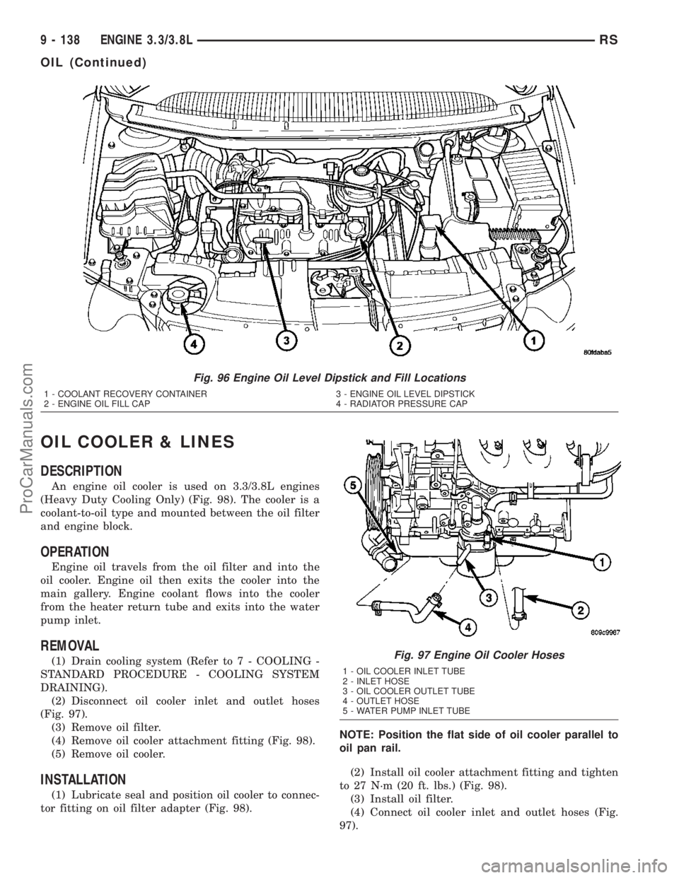
An engine oil cooler is used on 3.3/3.8L engines
(Heavy Duty Cooling Only) (Fig. 98). The cooler is a
coolant-to-oil type and mounted between the oil filter
and engine block.
OPERATION
Engine oil travels from the oil filter and into the
oil cooler. Engine oil then exits the cooler into the
main gallery. Engine coolant flows into the cooler
from the heater return tube and exits into the water
pump inlet.
REMOVAL
(1) Drain cooling system (Refer to 7 - COOLING -
STANDARD PROCEDURE - COOLING SYSTEM
DRAINING).
(2) Disconnect oil cooler inlet and outlet hoses
(Fig. 97).
(3) Remove oil filter.
(4) Remove oil cooler attachment fitting (Fig. 98).
(5) Remove oil cooler.
INSTALLATION
(1) Lubricate seal and position oil cooler to connec-
tor fitting on oil filter adapter (Fig. 98).NOTE: Position the flat side of oil cooler parallel to
oil pan rail.
(2) Install oil cooler attachment fitting and tighten
to 27 N´m (20 ft. lbs.) (Fig. 98).
(3) Install oil filter.
(4) Connect oil cooler inlet and outlet hoses (Fig.
97).
Fig. 96 Engine Oil Level Dipstick and Fill Locations
1 - COOLANT RECOVERY CONTAINER 3 - ENGINE OIL LEVEL DIPSTICK
2 - ENGINE OIL FILL CAP 4 - RADIATOR PRESSURE CAP
Fig. 97 Engine Oil Cooler Hoses
1 - OIL COOLER INLET TUBE
2 - INLET HOSE
3 - OIL COOLER OUTLET TUBE
4 - OUTLET HOSE
5 - WATER PUMP INLET TUBE
9 - 138 ENGINE 3.3/3.8LRS
OIL (Continued)
ProCarManuals.com
Page 1571 of 2177
TORQUE CONVERTER LEAKAGE
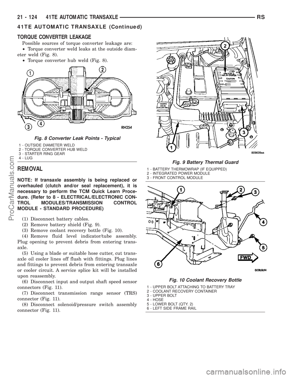
Possible sources of torque converter leakage are:
²Torque converter weld leaks at the outside diam-
eter weld (Fig. 8).
²Torque converter hub weld (Fig. 8).
REMOVAL
NOTE: If transaxle assembly is being replaced or
overhauled (clutch and/or seal replacement), it is
necessary to perform the TCM Quick Learn Proce-
dure. (Refer to 8 - ELECTRICAL/ELECTRONIC CON-
TROL MODULES/TRANSMISSION CONTROL
MODULE - STANDARD PROCEDURE)
(1) Disconnect battery cables.
(2) Remove battery shield (Fig. 9).
(3) Remove coolant recovery bottle (Fig. 10).
(4) Remove fluid level indicator/tube assembly.
Plug opening to prevent debris from entering trans-
axle.
(5) Using a blade or suitable hose cutter, cut trans-
axle oil cooler lines off flush with fittings. Plug lines
and fittings to prevent debris from entering transaxle
or cooler circuit. A service splice kit will be installed
upon reassembly.
(6) Disconnect input and output shaft speed sensor
connectors (Fig. 11).
(7) Disconnect transmission range sensor (TRS)
connector (Fig. 11).
(8) Disconnect solenoid/pressure switch assembly
connector (Fig. 11).
Fig. 8 Converter Leak Points - Typical
1 - OUTSIDE DIAMETER WELD
2 - TORQUE CONVERTER HUB WELD
3 - STARTER RING GEAR
4 - LUG
Fig. 9 Battery Thermal Guard
1 - BATTERY THERMOWRAP (IF EQUIPPED)
2 - INTEGRATED POWER MODULE
3 - FRONT CONTROL MODULE
Fig. 10 Coolant Recovery Bottle
1 - UPPER BOLT ATTACHING TO BATTERY TRAY
2 - COOLANT RECOVERY CONTAINER
3 - UPPER BOLT
4 - HOSE
5 - LOWER BOLT (QTY. 2)
6 - LEFT SIDE FRAME RAIL
21 - 124 41TE AUTOMATIC TRANSAXLERS
41TE AUTOMATIC TRANSAXLE (Continued)
ProCarManuals.com
Page 1615 of 2177
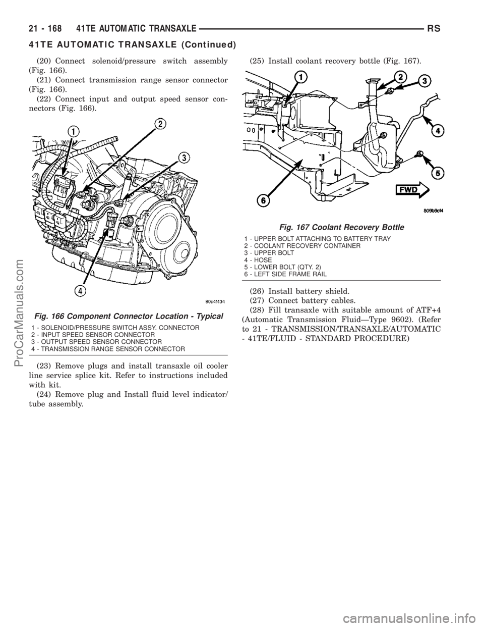
(20) Connect solenoid/pressure switch assembly
(Fig. 166).
(21) Connect transmission range sensor connector
(Fig. 166).
(22) Connect input and output speed sensor con-
nectors (Fig. 166).
(23) Remove plugs and install transaxle oil cooler
line service splice kit. Refer to instructions included
with kit.
(24) Remove plug and Install fluid level indicator/
tube assembly.(25) Install coolant recovery bottle (Fig. 167).
(26) Install battery shield.
(27) Connect battery cables.
(28) Fill transaxle with suitable amount of ATF+4
(Automatic Transmission FluidÐType 9602). (Refer
to 21 - TRANSMISSION/TRANSAXLE/AUTOMATIC
- 41TE/FLUID - STANDARD PROCEDURE)
Fig. 166 Component Connector Location - Typical
1 - SOLENOID/PRESSURE SWITCH ASSY. CONNECTOR
2 - INPUT SPEED SENSOR CONNECTOR
3 - OUTPUT SPEED SENSOR CONNECTOR
4 - TRANSMISSION RANGE SENSOR CONNECTOR
Fig. 167 Coolant Recovery Bottle
1 - UPPER BOLT ATTACHING TO BATTERY TRAY
2 - COOLANT RECOVERY CONTAINER
3 - UPPER BOLT
4 - HOSE
5 - LOWER BOLT (QTY. 2)
6 - LEFT SIDE FRAME RAIL
21 - 168 41TE AUTOMATIC TRANSAXLERS
41TE AUTOMATIC TRANSAXLE (Continued)
ProCarManuals.com
Page 1999 of 2177
²air recirculation button. The Recirculate button
contains an LED that illuminates to show when the
function is in operation.
²an air conditioning button that allows the com-
pressor to be turned on/off. The Snowflake button
contains an LED that illuminates to shown when the
function is in operation.
²rotary knobs for front and rear fan speed selec-
tion.
²a rotary knob for mode control.
REAR CONTROL PANEL
A rear control panel centrally mounted on the
headliner has a rotary adjustment for temperature
and fan speed control of the rear unit by intermedi-
ate seat passengers when the front control rear knob
is set to the rear position.
DESCRIPTION - AUTOMATIC TEMPERATURE
CONTROL
The Automatic Temperature Control (ATC) allows
occupants to select a comfort temperature, which is
the perceived temperature level not the actual pas-
senger compartment air temperature.
The Automatic Temperature Control system
includes a dust and odor air filter. The filter element
is the same size as the air conditioning evaporator to
ensure ample capacity. A door at the base of the
heater and air conditioning housing below the glove
box provides easy access to the filter element.
The ATC computer utilizes integrated circuitry and
information carried on the Programmable Communi-
cations Interface (PCI) data bus network to monitor
many sensors and switch inputs throughout the vehi-
cle. In response to those inputs, the internal circuitry
and programming of the ATC computer allow it to
control electronic functions and features of the ATC
system. The inputs to the ATC computer are:
²Vehicle Speed/Engine RPM± The ATC com-
puter monitors engine RPM, vehicle speed and Man-
ifold Absolute Pressure information from the PCM.
²Coolant Temperature± ATC computer moni-
tors Coolant temperature received from the PCM and
converts it to degrees Fahrenheit.
²Ambient Temperature± ATC computer moni-
tors Ambient temperature from the Compass Mini
Trip Computer (CMTC) and converts it to degrees
Fahrenheit.
²Engine Miscellaneous Sensor Status±ATC
computer monitors A/C disable information from the
PCM.
²Refrigerant Pressure± ATC computer moni-
tors Barometric Pressure, Intake Air Temperature,
High Side Pressure and Methanol Content as broad-
cast by the PCM.²Door Ajar Status± The ATC computer moni-
tors Driver Front Door, Passenger Front Door, Left
Rear Door, Right Rear Door and Liftgate ajar infor-
mation, as identified by the Body Control Module
(BCM), to determine if all in-car temperatures should
be maintained.
²Dimming± The ATC computer monitors dim-
ming status from the BCM to determine the required
level of brightness and will dim accordingly.
²Vehicle Odometer± The ATC computer moni-
tors the vehicle odometer information from the BCM
to prevent flashing the VF tube icons if the manual
motor calibration or manual cool down tests have
failed. Flashing of the display icons will cease when
the vehicle odometer is greater than 3 miles.
²English/Metric± The ATC computer monitors
the English/Metric information broadcast by the
CMTC. The set temp displays for both the front and
rear control heads will be set accordingly.
²Vehicle Identification Number± The ATC
computer monitors the last eight characters of the
VIN broadcast by the PCM and compares it to the
information stored in EEPROM. If it is different, the
new number will be stored over the old one and a
motor calibration shall be initiated.
²A/C System Information± The ATC computer
will send a message for Evaporator Temperature too
Low, Fan Blower Relay status, Evaporator Sensor
Failure, Rear Window Defogger Relay and A/C Select.
FRONT CONTROL PANEL
The front control panel and integral computer is
mounted in the instrument panel.
The instrument panel mounted control and inte-
gral computer contains:
²A power button which allows the system to be
completely turned off. The display is blank when the
system is off.
²Three rocker switches that select comfort tem-
peratures from 15É to 30É C (59É to 85É F), which are
shown in the vacuum-fluorescent digital control dis-
play. If the set temp is 59 and the down button is
pressed, the set temp value will become 55 but the
display will show LO. If the set temp is 85 and the
up button is pressed, the set temp value will become
90 but the display will show HIGH. Temperatures
can be displayed in either metric or Fahrenheit,
which is controlled from the overhead console.
²A rocker switch that selects a cool-down rate.
LO-AUTO or HI-AUTO are displayed when the sys-
tem is in automatic operation.
²A defroster button which turns on the defroster
independently during full automatic control. A
defroster symbol illuminates in the display when the
button is pressed.
24 - 2 HEATING & AIR CONDITIONINGRS
HEATING & AIR CONDITIONING (Continued)
ProCarManuals.com