2003 CHRYSLER VOYAGER center console
[x] Cancel search: center consolePage 983 of 2177

Component Page
C313 (Rear Console)................. 8W-80-39
C313 (Rear Console)................. 8W-80-39
C314 (Highline).................... 8W-80-40
C314 (Highline).................... 8W-80-40
C315 (Highline).................... 8W-80-41
C315 (Highline).................... 8W-80-41
C316 (Power Sliding Door)............ 8W-80-41
C316 (Power Sliding Door)............ 8W-80-42
C317 (Power Sliding Door)............ 8W-80-42
C317 (Power Sliding Door)............ 8W-80-42
C318 (Trailer Tow).................. 8W-80-43
C318 (Trailer Tow).................. 8W-80-43
C319 (Lowline)..................... 8W-80-43
C319 (Lowline)..................... 8W-80-44
C320............................. 8W-80-44
C320............................. 8W-80-44
C321............................. 8W-80-44
C321............................. 8W-80-45
C322 (Memory)..................... 8W-80-45
C322 (Memory)..................... 8W-80-45
C324 (Manual Sliding Door)........... 8W-80-46
C324 (Manual Sliding Door)........... 8W-80-46
C325 (Manual Sliding Door)........... 8W-80-46
C325 (Manual Sliding Door)........... 8W-80-46
C326............................. 8W-80-46
C326............................. 8W-80-47
C327............................. 8W-80-47
C327............................. 8W-80-47
C328 (Sunroof)..................... 8W-80-47
C328 (Sunroof)..................... 8W-80-47
C329 (Diesel)...................... 8W-80-48
C329 (Diesel)...................... 8W-80-48
C330 (Diesel)...................... 8W-80-48
C330 (Diesel)...................... 8W-80-48
C331 (Diesel)...................... 8W-80-48
C331 (Diesel)...................... 8W-80-49
C332 (3 Zone ATC).................. 8W-80-49
C332 (3 Zone ATC).................. 8W-80-49
Cabin Heater Assist C1 (Diesel)........ 8W-80-50
Cabin Heater Assist C2 (Diesel)........ 8W-80-50
Camshaft Position Sensor (Diesel)...... 8W-80-50
Camshaft Position Sensor (Gas)........ 8W-80-50
CD Changer....................... 8W-80-51
Center Dome Lamp (Base/Highline)..... 8W-80-51
Center High Mounted Stop Lamp....... 8W-80-51
Clockspring C1..................... 8W-80-51
Clockspring C2..................... 8W-80-52
Clockspring C3..................... 8W-80-52
Clockspring C4..................... 8W-80-52
Clutch Pedal Interlock Switch (MTX).... 8W-80-52
Clutch Pedal Upstop Switch (Diesel).... 8W-80-52
Controller Antilock Brake............. 8W-80-53
Crank Case Ventilation Heater (Diesel) . . 8W-80-53
Crankshaft Position Sensor (Diesel)..... 8W-80-53Component Page
Crankshaft Position Sensor (Gas)....... 8W-80-54
Data Link Connector................ 8W-80-54
Dosing Pump (Diesel)................ 8W-80-54
Driver Airbag Squib 1................ 8W-80-55
Driver Airbag Squib 2................ 8W-80-55
Driver Blend Door Actuator (ATC)...... 8W-80-55
Driver Blend Door Actuator (MTC)...... 8W-80-55
Driver Door Courtesy Lamp........... 8W-80-56
Driver Door Lock Switch............. 8W-80-56
Driver Heated Seat Back............. 8W-80-56
Driver Heated Seat Cushion........... 8W-80-56
Driver Heated Seat Module C1......... 8W-80-56
Driver Heated Seat Module C2......... 8W-80-57
Driver Heated Seat Module C3......... 8W-80-57
Driver Power Seat Front Riser Motor.... 8W-80-57
Driver Power Seat Front Riser Position
Sensor......................... 8W-80-57
Driver Power Seat Horizontal Motor.... 8W-80-58
Driver Power Seat Horizontal Position
Sensor......................... 8W-80-58
Driver Power Seat Rear Riser Motor.... 8W-80-58
Driver Power Seat Rear Riser Position
Sensor......................... 8W-80-58
Driver Power Seat Recliner Motor...... 8W-80-58
Driver Power Seat Recliner Position
Sensor......................... 8W-80-59
Driver Power Seat Switch............ 8W-80-59
Driver Power Window Motor.......... 8W-80-59
Driver Power Window Switch
(LHD Except Lowline)............. 8W-80-60
Driver Power Window Switch (LHD
Lowline)........................ 8W-80-60
Driver Power Window Switch (RHD).... 8W-80-60
Driver Seat Belt Switch.............. 8W-80-61
Driver Seat Belt Tensioner............ 8W-80-61
DVD Screen....................... 8W-80-61
DVD/CD Changer C1................ 8W-80-61
DVD/CD Changer C2................ 8W-80-62
DVD/CD Changer C3................ 8W-80-62
EGR Solenoid (3.3L/3.8L Export)....... 8W-80-62
EGR Solenoid (Diesel)............... 8W-80-62
Engine Control Module C1 (Diesel)..... 8W-80-63
Engine Control Module C2 (Diesel)..... 8W-80-64
Engine Coolant Temp Sensor (Diesel).... 8W-80-65
Engine Coolant Temp Sensor (Gas)..... 8W-80-65
Engine Oil Pressure Sensor (Diesel)..... 8W-80-66
Engine Oil Pressure Switch (Gas)...... 8W-80-66
EVAP/Purge Solenoid (Gas)........... 8W-80-66
Evaporator Temperature Sensor........ 8W-80-66
Floor Console Lamp................. 8W-80-67
Floor Console Power Outlet........... 8W-80-67
Front Blower Module C1 (ATC)........ 8W-80-67
Front Blower Module C2 (ATC)........ 8W-80-67
Front Cigar Lighter................. 8W-80-68
8W - 80 - 2 8W-80 CONNECTOR PIN-OUTSRS
ProCarManuals.com
Page 985 of 2177

Component Page
Liftgate Cinch/Release Motor (Power
Liftgate)........................ 8W-80-92
Liftgate Cylinder Lock Switch (Export) . . 8W-80-92
Liftgate Left Pinch Sensor (Power
Liftgate)........................ 8W-80-92
Liftgate Right Pinch Sensor (Power
Liftgate)........................ 8W-80-92
Low Note Horn..................... 8W-80-92
Manifold Absolute Pressure Sensor (Gas) . 8W-80-93
Mass Air Flow Sensor (Diesel)......... 8W-80-93
Memory Seat/Mirror Module C1........ 8W-80-93
Memory Seat/Mirror Module C2........ 8W-80-94
Memory Seat/Mirror Module C3........ 8W-80-94
Memory Seat/Mirror Module C4........ 8W-80-94
Memory Set Switch................. 8W-80-95
Message Center (Highline)............ 8W-80-95
Mode Door Actuator (ATC)............ 8W-80-95
Mode Door Actuator (MTC)........... 8W-80-95
Multi-Function Switch............... 8W-80-96
Natural Vacuum Leak Detection Assembly
(2.4L Except Export)............... 8W-80-96
Output Speed Sensor (EATX).......... 8W-80-96
Overhead Console (Except Base)....... 8W-80-96
Oxygen Sensor 1/1 Upstream (Gas)..... 8W-80-97
Oxygen Sensor 1/2 Downstream (Gas) . . . 8W-80-97
Passenger Airbag................... 8W-80-97
Passenger Blend Door Actuator (ATC) . . . 8W-80-97
Passenger Blend Door Actuator (MTC) . . . 8W-80-98
Passenger Door Courtesy Lamp........ 8W-80-98
Passenger Door Lock Switch........... 8W-80-98
Passenger Folding Mirror Relay (Export) . 8W-80-98
Passenger Heated Seat Back.......... 8W-80-99
Passenger Heated Seat Cushion........ 8W-80-99
Passenger Heated Seat Module C1...... 8W-80-99
Passenger Heated Seat Module C2...... 8W-80-99
Passenger Heated Seat Module C3..... 8W-80-100
Passenger Power Seat Front Riser
Motor......................... 8W-80-100
Passenger Power Seat Horizontal
Motor......................... 8W-80-100
Passenger Power Seat Rear Riser
Motor......................... 8W-80-100
Passenger Power Seat Recliner Motor . . 8W-80-100
Passenger Power Seat Switch......... 8W-80-101
Passenger Power Window Motor....... 8W-80-101
Passenger Power Window Switch...... 8W-80-101
Passenger Seat Belt Switch.......... 8W-80-101
Passenger Seat Belt Tensioner........ 8W-80-102
Power Folding Mirror Switch (Export) . . 8W-80-102
Power Liftgate Module C1........... 8W-80-102
Power Liftgate Module C2........... 8W-80-103
Power Liftgate Motor............... 8W-80-103
Power Mirror Switch............... 8W-80-104
Power Outlet (Except Lowline)........ 8W-80-104
Power Seat Circuit Breaker (30A)..... 8W-80-104Component Page
Power Window Circuit Breaker (25A) . . . 8W-80-104
Power Window Switch (LHD Lowline) . . 8W-80-105
Powertrain Control Module C1 (NGC) . . 8W-80-105
Powertrain Control Module C1
(SBEC)........................ 8W-80-106
Powertrain Control Module C2 (NGC) . . 8W-80-107
Powertrain Control Module C2 (SBEC) . 8W-80-108
Powertrain Control Module C3 (NGC) . . 8W-80-109
Powertrain Control Module C4 (NGC)
(EATX) ........................ 8W-80-110
Radiator Fan No. 1 (Diesel).......... 8W-80-111
Radiator Fan No. 1 (Gas)............ 8W-80-111
Radiator Fan No. 2 (Diesel).......... 8W-80-111
Radiator Fan No. 2 (Gas)............ 8W-80-111
Radiator Fan Relay (Gas)............ 8W-80-112
Radiator Fan Relay No. 1 (Diesel)..... 8W-80-112
Radiator Fan Relay No. 2 (Diesel)..... 8W-80-112
Radiator Fan Relay No. 3 (Diesel)..... 8W-80-113
Radio C1......................... 8W-80-113
Radio C2 (CD Changer)............. 8W-80-114
Radio C2 (DVD/CD Changer)......... 8W-80-114
Rear A/C-Heater Unit (3 Zone MTC).... 8W-80-114
Rear Auto Temp Control Switch
(3 Zone ATC).................... 8W-80-115
Rear Blower Front Control Switch
(3 Zone MTC)................... 8W-80-115
Rear Blower Motor Power Module C1
(3 Zone ATC).................... 8W-80-115
Rear Blower Motor Power Module C2
(3 Zone ATC).................... 8W-80-116
Rear Blower Rear Control Switch C1
(3 Zone MTC)................... 8W-80-116
Rear Blower Rear Control Switch C2
(3 Zone MTC)................... 8W-80-116
Rear Dome Lamp (Except Luxury)..... 8W-80-116
Rear Intrusion Sensor (United
Kingdom)...................... 8W-80-117
Rear Mode Motor (3 Zone ATC)........ 8W-80-117
Rear Power Outlet................. 8W-80-117
Rear Temperature Motor (3 Zone ATC) . . 8W-80-117
Rear Washer Pump Motor............ 8W-80-118
Rear Wiper Motor.................. 8W-80-118
Recirculation Door Actuator (ATC)..... 8W-80-118
Recirculation Door Actuator (MTC)..... 8W-80-118
Remote Keyless Entry Antenna
(Japan)........................ 8W-80-119
Remote Keyless Entry Module........ 8W-80-119
Right B-Pillar Switch (Power Sliding
Door).......................... 8W-80-119
Right Cinch/Release Motor
(Power Sliding Door).............. 8W-80-119
Right Combination Relay
(Trailer Tow).................... 8W-80-120
Right Cylinder Lock Switch (Export) . . . 8W-80-120
Right Door Speaker (Lowline)......... 8W-80-120
8W - 80 - 4 8W-80 CONNECTOR PIN-OUTSRS
ProCarManuals.com
Page 1123 of 2177

CONNECTOR NAME/NUMBER COLOR LOCATION FIG.
Memory Seat Horizontal Position
SensorBK Under Seat N/S
Memory Seat Rear Vertical Motor RD Under Seat N/S
Memory Seat Rear Vertical
Position SensorBK Under Seat N/S
Memory Seat Recliner Motor GN Under Seat N/S
Memory Seat Recliner Position
SensorBK Under Seat N/S
Memory Seat Switch BK At Switch Driver Door 42
Message Center WT Rear of Message Center 19, 20, 27
Mode Door Actuator GY Left Side of HVAC N/S
Multi Function Switch BK At Steering Column 19, 20, 21, 22, 30
Natural Vacuum Leak Detection
AssemblyBK Top of Engine 12
Output Speed Sensor GY Front of Transmission 14, 18
Overhead Console BK Front of Console N/S
Oxygen Sensor 1/1 Upstream BK Rear of Engine 10,11, 12, 18
Oxygen Sensor 1/2 Downstream BK Rear of Engine 10, 11, 12,18
Park/Neutral Positon Switch BK Front of Transmission 11
Passenger Airbag YL Passenger Side of Instrument Panel 19, 22, 23 28
Passenger Blend Door Actuator On HVAC N/S
Passenger Door Courtesy Lamp BK At Lamp 43
Passenger Door Lock Switch BK At Switch 43
Passenger Folding Mirror Relay BL Left Kick Panel 7
Passenger Heated Seat Back GN At Seat N/S
Passenger Heated Seat Cushion BK At Seat N/S
Passenger Heated Seat Module
C1GY At Heated Seat N/S
Passenger Heated Seat Module
C2GY At Heated Seat Back N/S
Passenger Heated Seat Module
C3GN At Heated Seat N/S
Passenger Power Seat Front
Riser MotorRD Under Seat N/S
Passenger Power Seat Horizontal
MotorBK Under Seat N/S
Passenger Power Seat Rear
Riser MotorRD Under Seat N/S
Passenger Power Seat Recliner
MotorGN Under Seat N/S
Passenger Power Seat Switch GN At Switch N/S
Passenger Power Window Motor RD At Motor 43
Passenger Power Window Switch BK At Switch 43
Passenger Seat Belt Switch On Seat Harness N/S
Passenger Seat Belt Tensioner On Seat Harness N/S
8W - 91 - 8 8W-91 CONNECTOR/GROUND/SPLICE LOCATIONRS
CONNECTOR/GROUND/SPLICE LOCATION (Continued)
ProCarManuals.com
Page 1178 of 2177
The IPM has a molded plastic cover that can be
removed to provide service access to all of the fuses
and relays in the IPM. An integral latch and hinges
are molded into the IPM cover for easy removal. A
fuse layout map is integral to the underside of the
IPM cover to ensure proper fuse and relay identifica-
tion. The IOD fuse is a 20 ampere blade-type mini
fuse and, when removed, it is stored in a fuse cavity
adjacent to the washer fuse within the IPM.
OPERATION
The term ignition-off draw identifies a normal con-
dition where power is being drained from the battery
with the ignition switch in the Off position. The IOD
fuse feeds the memory and sleep mode functions for
some of the electronic modules in the vehicle as well
as various other accessories that require battery cur-
rent when the ignition switch is in the Off position,
including the clock. The only reason the IOD fuse is
removed is to reduce the normal IOD of the vehicle
electrical system during new vehicle transportation
and pre-delivery storage to reduce battery depletion,
while still allowing vehicle operation so that the
vehicle can be loaded, unloaded and moved as needed
by both vehicle transportation company and dealer
personnel.
The IOD fuse is removed from the IPM fuse cavity
when the vehicle is shipped from the assembly plant.
Dealer personnel must install the IOD fuse when the
vehicle is being prepared for delivery in order to
restore full electrical system operation. Once the
vehicle is prepared for delivery, the IOD function of
this fuse becomes transparent and the fuse that has
been assigned the IOD designation becomes only
another Fused B(+) circuit fuse. The IOD fuse serves
no useful purpose to the dealer technician in the ser-
vice or diagnosis of any vehicle system or condition,
other than the same purpose as that of any other
standard circuit protection device.
The IOD fuse can be used by the vehicle owner as
a convenient means of reducing battery depletion
when a vehicle is to be stored for periods not to
exceed about thirty days. However, it must be
remembered that removing the IOD fuse will not
eliminate IOD, but only reduce this normal condition.
If a vehicle will be stored for more than about thirty
days, the battery negative cable should be discon-
nected to eliminate normal IOD; and, the battery
should be tested and recharged at regular intervals
during the vehicle storage period to prevent the bat-
tery from becoming discharged or damaged. Refer to
Battery Systemfor additional service information.
REMOVAL
(1) Turn the ignition switch to the Off position.(2) Unlatch and open the cover of the intelligent
power module.
(3) Remove the IOD fuse from fuse location
markedIODof the Integrated Power Module (IPM).
(4) Store the removed IOD fuse by installing it in
the unused fuse storage markedSPAREof the IPM.
(5) Close and latch the IPM.
INSTALLATION
(1) Be certain the ignition switch is in the Off posi-
tion.
(2) Unlatch and open the cover of the Integrated
Power Module (IPM).
(3) Use a thumb to press the IOD fuse firmly down
into IPM fuse cavity markedIOD.
(4) Close and latch the IPM cover.
POWER OUTLET
DESCRIPTION
Accessory power outlets are standard equipment on
this model. Two power outlets are installed in the
instrument panel center lower bezel, which is located
near the bottom of the instrument panel center stack
area. Two additional power outlets are also incorpo-
rated into the vehicle, one on the left rear C-pillar
trim and the other in the center console, if equipped.
The power outlets bases are secured by a snap fit in
the appropriate bezels. A hinged plug flips closed to
conceal and protect the power outlet base when the
power outlet is not being used.
The power outlet receptacle unit and the power
outlet plugs are each available for service replace-
ment.
OPERATION
The power outlet base or receptacle shell is con-
nected to ground, and an insulated contact in the
bottom of the shell is connected to battery current.
The power outlet on the instrument panel marked
with a battery receives battery voltage from a fuse in
the Integrated Power Module (IPM) at all times. The
other power outlet on the instrument panel marked
with a key receives battery voltage only when the
key is in the on position.
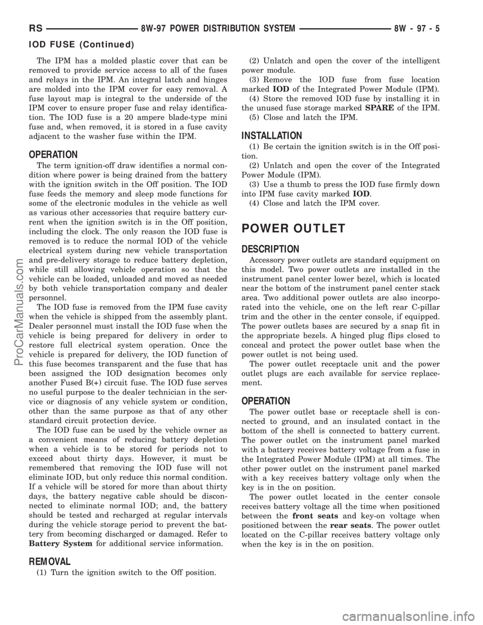
The power outlet located in the center console
receives battery voltage all the time when positioned
between thefront seatsand key-on voltage when
positioned between therear seats. The power outlet
located on the C-pillar receives battery voltage only
when the key is in the on position.
RS8W-97 POWER DISTRIBUTION SYSTEM8W-97-5
IOD FUSE (Continued)
ProCarManuals.com
Page 1519 of 2177
FLUID DRAIN
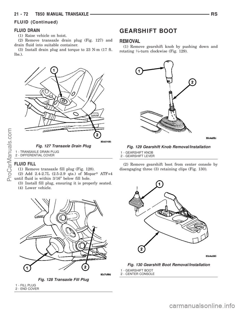
(1) Raise vehicle on hoist.
(2) Remove transaxle drain plug (Fig. 127) and
drain fluid into suitable container.
(3) Install drain plug and torque to 23 N´m (17 ft.
lbs.).
FLUID FILL
(1) Remove transaxle fill plug (Fig. 128).
(2) Add 2.4-2.7L (2.5-2.9 qts.) of MopartATF+4
until fluid is within 3/16º below fill hole.
(3) Install fill plug, ensuring it is properly seated.
(4) Lower vehicle.
GEARSHIFT BOOT
REMOVAL
(1) Remove gearshift knob by pushing down and
rotating1¤4-turn clockwise (Fig. 129).
(2) Remove gearshift boot from center console by
disengaging three (3) retaining clips (Fig. 130).
Fig. 127 Transaxle Drain Plug
1 - TRANSAXLE DRAIN PLUG
2 - DIFFERENTIAL COVER
Fig. 128 Transaxle Fill Plug
1 - FILL PLUG
2 - END COVER
Fig. 129 Gearshift Knob Removal/Installation
1 - GEARSHIFT KNOB
2 - GEARSHIFT LEVER
Fig. 130 Gearshift Boot Removal/Installation
1 - GEARSHIFT BOOT
2 - CENTER CONSOLE
21 - 72 T850 MANUAL TRANSAXLERS
FLUID (Continued)
ProCarManuals.com
Page 1520 of 2177
INSTALLATION
(1) Install gearshift boot to console and secure
with three (3) retaining clips (Fig. 130).
(2) Install gearshift knob (Fig. 129). Orient shift
pattern
1¤4-turn clockwise, press down, and rotate1¤4-
turn counter-clockwise.
(3) Secure gearshift boot to base of knob.
GEARSHIFT CABLE -
CROSSOVER
REMOVAL
(1) Disconnect battery negative cable.
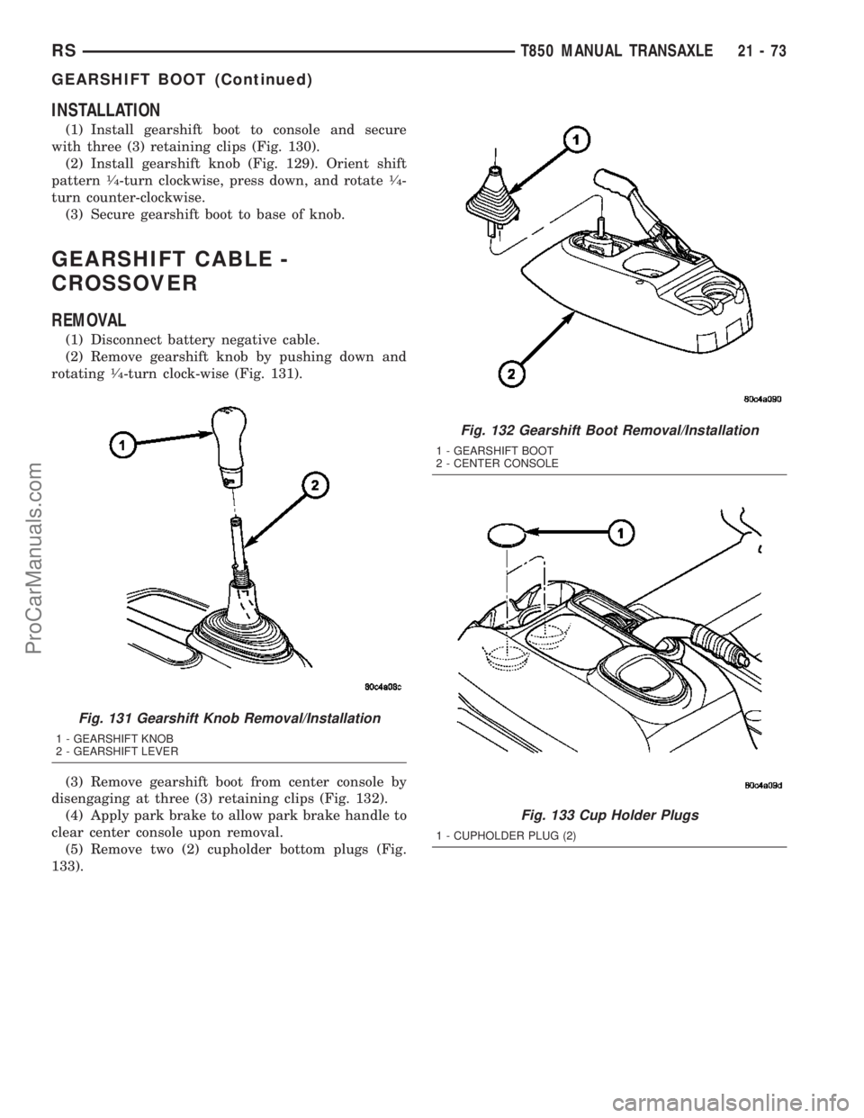
(2) Remove gearshift knob by pushing down and
rotating
1¤4-turn clock-wise (Fig. 131).
(3) Remove gearshift boot from center console by
disengaging at three (3) retaining clips (Fig. 132).
(4) Apply park brake to allow park brake handle to
clear center console upon removal.
(5) Remove two (2) cupholder bottom plugs (Fig.
133).
Fig. 131 Gearshift Knob Removal/Installation
1 - GEARSHIFT KNOB
2 - GEARSHIFT LEVER
Fig. 132 Gearshift Boot Removal/Installation
1 - GEARSHIFT BOOT
2 - CENTER CONSOLE
Fig. 133 Cup Holder Plugs
1 - CUPHOLDER PLUG (2)
RST850 MANUAL TRANSAXLE21-73
GEARSHIFT BOOT (Continued)
ProCarManuals.com
Page 1521 of 2177
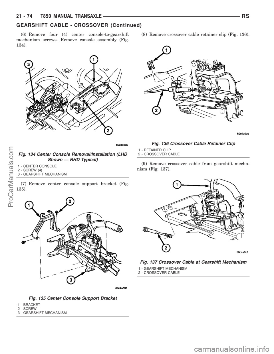
(6) Remove four (4) center console-to-gearshift
mechanism screws. Remove console assembly (Fig.
134).
(7) Remove center console support bracket (Fig.
135).(8) Remove crossover cable retainer clip (Fig. 136).
(9) Remove crossover cable from gearshift mecha-
nism (Fig. 137).
Fig. 134 Center Console Removal/Installation (LHD
Shown Ð RHD Typical)
1 - CENTER CONSOLE
2 - SCREW (4)
3 - GEARSHIFT MECHANISM
Fig. 135 Center Console Support Bracket
1 - BRACKET
2 - SCREW
3 - GEARSHIFT MECHANISM
Fig. 136 Crossover Cable Retainer Clip
1 - RETAINER CLIP
2 - CROSSOVER CABLE
Fig. 137 Crossover Cable at Gearshift Mechanism
1 - GEARSHIFT MECHANISM
2 - CROSSOVER CABLE
21 - 74 T850 MANUAL TRANSAXLERS
GEARSHIFT CABLE - CROSSOVER (Continued)
ProCarManuals.com
Page 1525 of 2177
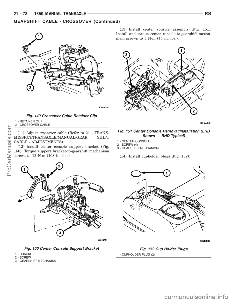
(11) Adjust crossover cable (Refer to 21 - TRANS-
MISSION/TRANSAXLE/MANUAL/GEAR SHIFT
CABLE - ADJUSTMENTS).
(12) Install center console support bracket (Fig.
150). Torque support bracket-to-gearshift mechanism
screws to 12 N´m (108 in. lbs.).(13) Install center console assembly (Fig. 151).
Install and torque center console-to-gearshift mecha-
nism screws to 5 N´m (45 in. lbs.).
(14) Install cupholder plugs (Fig. 152).
Fig. 149 Crossover Cable Retainer Clip
1 - RETAINER CLIP
2 - CROSSOVER CABLE
Fig. 150 Center Console Support Bracket
1 - BRACKET
2 - SCREW
3 - GEARSHIFT MECHANISM
Fig. 151 Center Console Removal/Installation (LHD
Shown Ð RHD Typical)
1 - CENTER CONSOLE
2 - SCREW (4)
3 - GEARSHIFT MECHANISM
Fig. 152 Cup Holder Plugs
1 - CUPHOLDER PLUG (2)
21 - 78 T850 MANUAL TRANSAXLERS
GEARSHIFT CABLE - CROSSOVER (Continued)
ProCarManuals.com