Page 1454 of 2177

ADJUSTMENTS
OUTPUT FLANGE SHIM SELECTION
This procedure is used when the output flange is
replaced. Replacement of the output flange requires
installation of the correct size shim to maintain bear-
ing preload.The shim must protrude from the
new output flange the same distance that the
original shim protruded from the original
flange.
(1) Stand the original output flange on end with
shim side pointing up.
(2) Place original shim into groove in top of flange.
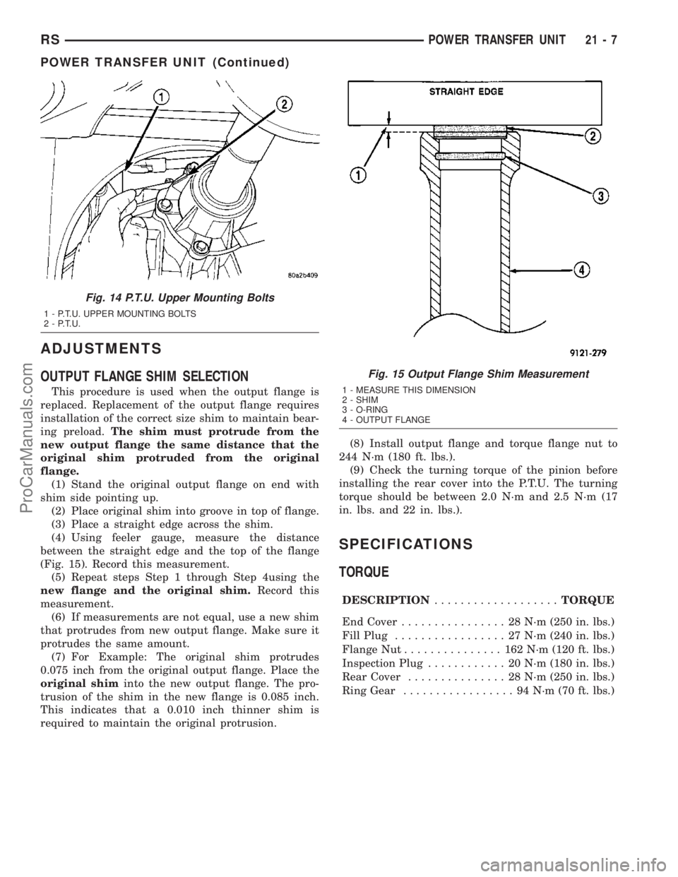
(3) Place a straight edge across the shim.
(4) Using feeler gauge, measure the distance
between the straight edge and the top of the flange
(Fig. 15). Record this measurement.
(5) Repeat steps Step 1 through Step 4using the
new flange and the original shim.Record this
measurement.
(6) If measurements are not equal, use a new shim
that protrudes from new output flange. Make sure it
protrudes the same amount.
(7) For Example: The original shim protrudes
0.075 inch from the original output flange. Place the
original shiminto the new output flange. The pro-
trusion of the shim in the new flange is 0.085 inch.
This indicates that a 0.010 inch thinner shim is
required to maintain the original protrusion.(8) Install output flange and torque flange nut to
244 N´m (180 ft. lbs.).
(9) Check the turning torque of the pinion before
installing the rear cover into the P.T.U. The turning
torque should be between 2.0 N´m and 2.5 N´m (17
in. lbs. and 22 in. lbs.).
SPECIFICATIONS
TORQUE
DESCRIPTION...................TORQUE
End Cover................ 28N´m(250 in. lbs.)
Fill Plug................. 27N´m(240 in. lbs.)
Flange Nut............... 162N´m(120 ft. lbs.)
Inspection Plug............ 20N´m(180 in. lbs.)
Rear Cover............... 28N´m(250 in. lbs.)
Ring Gear................. 94N´m(70ft.lbs.)
Fig. 14 P.T.U. Upper Mounting Bolts
1 - P.T.U. UPPER MOUNTING BOLTS
2 - P.T.U.
Fig. 15 Output Flange Shim Measurement
1 - MEASURE THIS DIMENSION
2 - SHIM
3 - O-RING
4 - OUTPUT FLANGE
RSPOWER TRANSFER UNIT21-7
POWER TRANSFER UNIT (Continued)
ProCarManuals.com
Page 1468 of 2177

T850 MANUAL TRANSAXLE
TABLE OF CONTENTS
page page
T850 MANUAL TRANSAXLE
DESCRIPTION.........................21
OPERATION...........................24
DIAGNOSIS AND TESTING - COMMON
PROBLEM CAUSES....................30
REMOVAL.............................31
DISASSEMBLY.........................35
ASSEMBLY............................42
INSTALLATION.........................51
SPECIFICATIONS - T850 MANUAL
TRANSAXLE.........................56
SPECIAL TOOLS - T850 TRANSAXLE........58
AXLE SEALS
REMOVAL.............................61
INSTALLATION.........................61
BACK-UP LAMP SWITCH
REMOVAL.............................62
INSTALLATION.........................62
DIFFERENTIAL
DESCRIPTION.........................62
OPERATION...........................62
DISASSEMBLY.........................62
ASSEMBLY............................66
ADJUSTMENTS
ADJUSTMENT - DIFFERENTIAL TURNING
TORQUE............................69
ADJUSTMENT - DIFFERENTIAL SIDE GEAR
ENDPLAY...........................70
FLUID
STANDARD PROCEDURE
STANDARD PROCEDURE - FLUID LEVEL
CHECK.............................71
STANDARD PROCEDURE - FLUID DRAIN
AND FILL............................71
GEARSHIFT BOOT
REMOVAL.............................72
INSTALLATION.........................73GEARSHIFT CABLE - CROSSOVER
REMOVAL.............................73
INSTALLATION.........................76
ADJUSTMENTS
ADJUSTMENT........................79
GEARSHIFT CABLE - SELECTOR
REMOVAL.............................81
INSTALLATION.........................84
GEARSHIFT KNOB
REMOVAL.............................87
INSTALLATION.........................87
GEARSHIFT MECHANISM
REMOVAL.............................87
INSTALLATION.........................89
INPUT SHAFT
DESCRIPTION.........................93
DISASSEMBLY.........................93
ASSEMBLY............................96
INTERMEDIATE SHAFT
DESCRIPTION........................100
DISASSEMBLY........................100
ASSEMBLY...........................107
SHIFT COVER
DESCRIPTION........................113
SHIFT FORK AND SHAFT
DESCRIPTION........................113
SYNCHRONIZER
DESCRIPTION........................114
DISASSEMBLY........................114
CLEANING
CLEAN.............................114
INSPECTION
INSPECT...........................114
ASSEMBLY...........................114
VEHICLE SPEED SENSOR
REMOVAL............................115
INSTALLATION........................115
T850 MANUAL TRANSAXLE
DESCRIPTION
The NV T850 5-speed transaxle (Fig. 1) is a con-
stant-mesh manual transaxle that is synchronized in
all gear ranges, including reverse.The transaxle consists of three major sub-assem-
blies: the input shaft, intermediate shaft, and differ-
ential assembly. The transaxle shift system consists
of a mechanical shift cover, rails, forks, and cables.
The unique design of this shift system provides a
higher mechanical advantage, resulting in less fric-
tion and lower shift cable loads for smoother, more
positive operation.
RST850 MANUAL TRANSAXLE21-21
ProCarManuals.com
Page 1487 of 2177

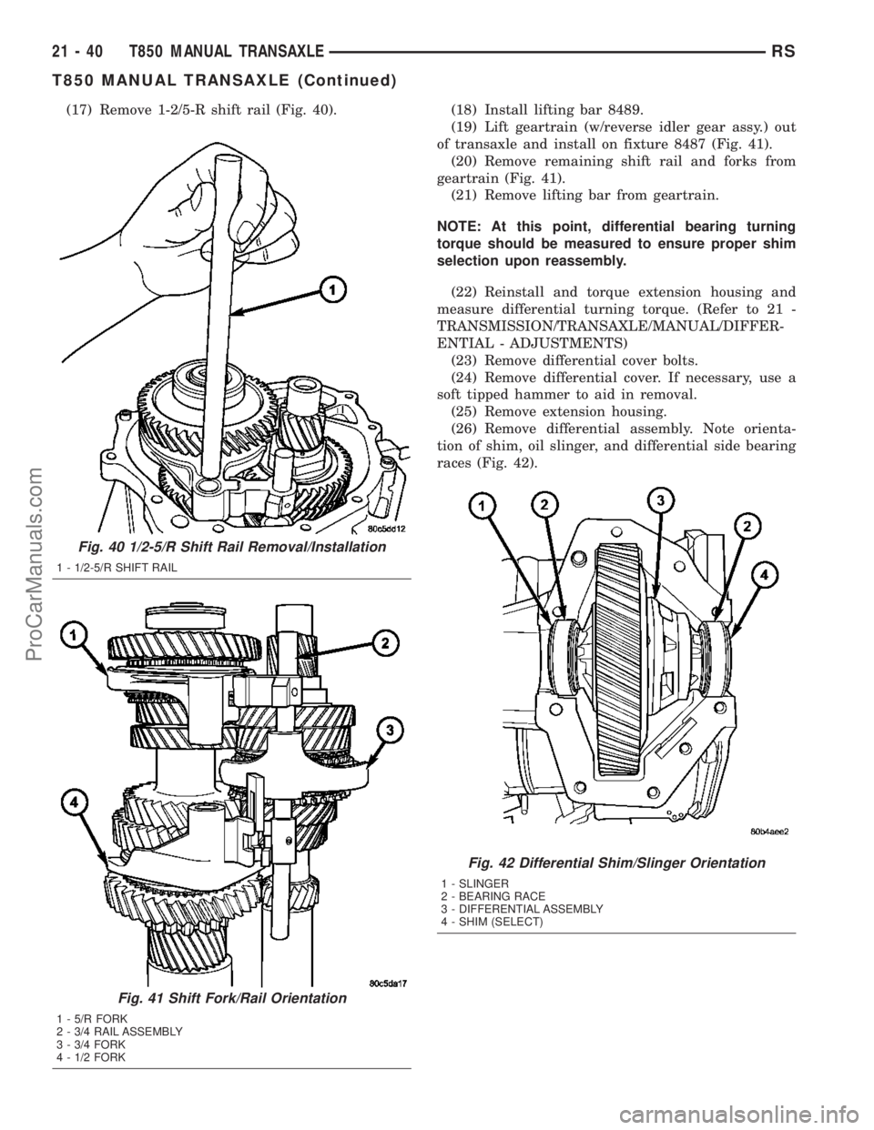
(17) Remove 1-2/5-R shift rail (Fig. 40). (18) Install lifting bar 8489.
(19) Lift geartrain (w/reverse idler gear assy.) out
of transaxle and install on fixture 8487 (Fig. 41).
(20) Remove remaining shift rail and forks from
geartrain (Fig. 41).
(21) Remove lifting bar from geartrain.
NOTE: At this point, differential bearing turning
torque should be measured to ensure proper shim
selection upon reassembly.
(22) Reinstall and torque extension housing and
measure differential turning torque. (Refer to 21 -
TRANSMISSION/TRANSAXLE/MANUAL/DIFFER-
ENTIAL - ADJUSTMENTS)
(23) Remove differential cover bolts.
(24) Remove differential cover. If necessary, use a
soft tipped hammer to aid in removal.
(25) Remove extension housing.
(26) Remove differential assembly. Note orienta-
tion of shim, oil slinger, and differential side bearing
races (Fig. 42).
Fig. 40 1/2-5/R Shift Rail Removal/Installation
1 - 1/2-5/R SHIFT RAIL
Fig. 41 Shift Fork/Rail Orientation
1 - 5/R FORK
2 - 3/4 RAIL ASSEMBLY
3 - 3/4 FORK
4 - 1/2 FORK
Fig. 42 Differential Shim/Slinger Orientation
1 - SLINGER
2 - BEARING RACE
3 - DIFFERENTIAL ASSEMBLY
4 - SHIM (SELECT)
21 - 40 T850 MANUAL TRANSAXLERS
T850 MANUAL TRANSAXLE (Continued)
ProCarManuals.com
Page 1489 of 2177
ASSEMBLY
NOTE: When assembling this transaxle, always use
NEW snap rings.
NOTE: Before assembling transaxle, differential
turning torque must be measured and adjusted.
(Refer to 21 - TRANSMISSION/TRANSAXLE/MANU-
AL/DIFFERENTIAL - ADJUSTMENTS). Differential
turning torque must be measured with geartrain out
of case.
(1) Install input shaft bearing using an arbor press
and remover/installer 8474 (Fig. 47).
(2) Install shift shaft bushing to case using
installer 8475 (Fig. 48).
Fig. 46 Input Shaft Bearing Removal
1 - ARBOR PRESS
2 - DRIVER HANDLE C-4171
3 - REMOVER/INSTALLER 8474
Fig. 47 Input Shaft Bearing Installation
1 - ARBOR PRESS
2 - C-4171 DRIVER HANDLE
3 - REMOVER/INSTALLER 8474
4 - INPUT SHAFT BEARING
Fig. 48 Shift Shaft Bushing Installation
1 - INSTALLER 8475
2 - SHIFT SHAFT BUSHING
21 - 42 T850 MANUAL TRANSAXLERS
T850 MANUAL TRANSAXLE (Continued)
ProCarManuals.com
Page 1491 of 2177
(6) Install lifting bar 8489 to geartrain. Install
geartrain to case.When installing geartrain to
case, use care not to damage bearing surfaces.
(7) Remove lifting bar 8489 from geartrain.
(8) Install shift 1/2-5/R rail as shown in (Fig. 52).
(9) Install reverse idler shaft into position (Fig.
53). Install and torque shaft-to-case bolt to 54 N´m
(40 ft. lbs.).
(10) Install reverse idler gear bearing (Fig. 54).
(11) Install reverse idler gear with hub down as
shown in (Fig. 55).
(12) Install flat washer (Fig. 56).
(13) Install wave washer (Fig. 57).
Fig. 51 Shift Fork/Rail Orientation
1 - 5/R FORK
2 - 3/4 RAIL ASSEMBLY
3 - 3/4 FORK
4 - 1/2 FORK
Fig. 52 Shift Rail Installation
1 - 1/2-5/R SHIFT RAIL
Fig. 53 Install Reverse Idler Shaft
1 - REVERSE IDLER SHAFT
2 - BOLT
21 - 44 T850 MANUAL TRANSAXLERS
T850 MANUAL TRANSAXLE (Continued)
ProCarManuals.com
Page 1493 of 2177
(14) Install input shaft sealed roller bearing using
installer 8482 (Fig. 58).
(15) Installnewinput shaft bearing snap ring
(Fig. 59).(16) Install shift rail bushing to end cover using
installer 8475 (Fig. 60).
(17) Applya1mm(0.04 in.) bead of MopartGas-
ket Maker to transaxle end cover and install to
transaxle case (Fig. 61).While installing end
cover, be sure to guide oil trough into pocket
(Fig. 62).Torque end cover-to-case bolts to 28 N´m
(250 in. lbs.) (Fig. 63).
Fig. 58 Install Input Shaft Sealed Roller Bearing
1 - INSTALLER 8482
2 - SEALED ROLLER BEARING
Fig. 59 Input Shaft Bearing Snap Ring
1 - SNAP RING
Fig. 60 Shift Rail Bushing Installation
1 - INSTALLER 8475
Fig. 61 End Cover Removal/Installation
1 - END COVER
2 - OIL TROUGH
21 - 46 T850 MANUAL TRANSAXLERS
T850 MANUAL TRANSAXLE (Continued)
ProCarManuals.com
Page 1494 of 2177
(18) Install lifting bar 8489 to geartrain.
(19) Lift up on bar (input shaft side) and install
input shaft bearing snap ring (Fig. 64).
(20) Lift up on bar (intermediate shaft side) and
install intermediate shaft bearing snap ring.
(21) Remove lifting bar 8489.
(22) Install a bead of MopartGear Lube RTV to
end plate and immediately install to case. Install and
torque bolts to 28 N´m (250 in. lbs.) (Fig. 65).
Fig. 62 Oil Trough Pocket
1 - OIL TROUGH
2 - POCKET
Fig. 63 End Cover Bolts
1 - BOLT (12)
Fig. 64 Input Bearing Snap Ring
1 - SNAP RING PLIERS
2 - LIFTING BAR 8489
3 - SNAP RING
Fig. 65 End Cover Bolts
1 - BOLT (11)
RST850 MANUAL TRANSAXLE21-47
T850 MANUAL TRANSAXLE (Continued)
ProCarManuals.com
Page 1495 of 2177

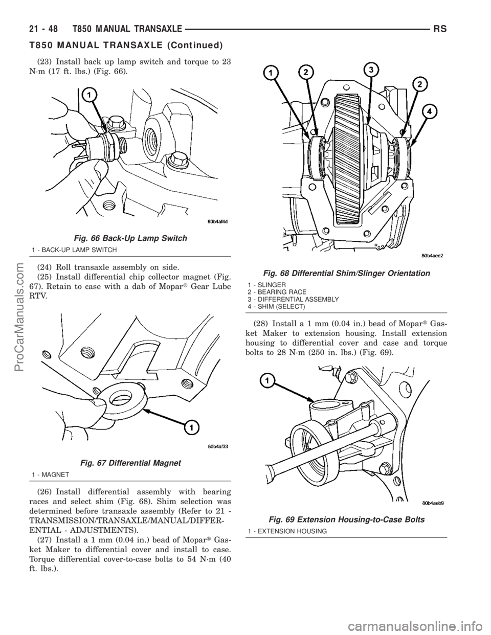
(23) Install back up lamp switch and torque to 23
N´m (17 ft. lbs.) (Fig. 66).
(24) Roll transaxle assembly on side.
(25) Install differential chip collector magnet (Fig.
67). Retain to case with a dab of MopartGear Lube
RTV.
(26) Install differential assembly with bearing
races and select shim (Fig. 68). Shim selection was
determined before transaxle assembly (Refer to 21 -
TRANSMISSION/TRANSAXLE/MANUAL/DIFFER-
ENTIAL - ADJUSTMENTS).
(27) Installa1mm(0.04 in.) bead of MopartGas-
ket Maker to differential cover and install to case.
Torque differential cover-to-case bolts to 54 N´m (40
ft. lbs.).(28) Installa1mm(0.04 in.) bead of MopartGas-
ket Maker to extension housing. Install extension
housing to differential cover and case and torque
bolts to 28 N´m (250 in. lbs.) (Fig. 69).
Fig. 66 Back-Up Lamp Switch
1 - BACK-UP LAMP SWITCH
Fig. 67 Differential Magnet
1 - MAGNET
Fig. 68 Differential Shim/Slinger Orientation
1 - SLINGER
2 - BEARING RACE
3 - DIFFERENTIAL ASSEMBLY
4 - SHIM (SELECT)
Fig. 69 Extension Housing-to-Case Bolts
1 - EXTENSION HOUSING
21 - 48 T850 MANUAL TRANSAXLERS
T850 MANUAL TRANSAXLE (Continued)
ProCarManuals.com