2003 CHRYSLER VOYAGER sensor
[x] Cancel search: sensorPage 1524 of 2177
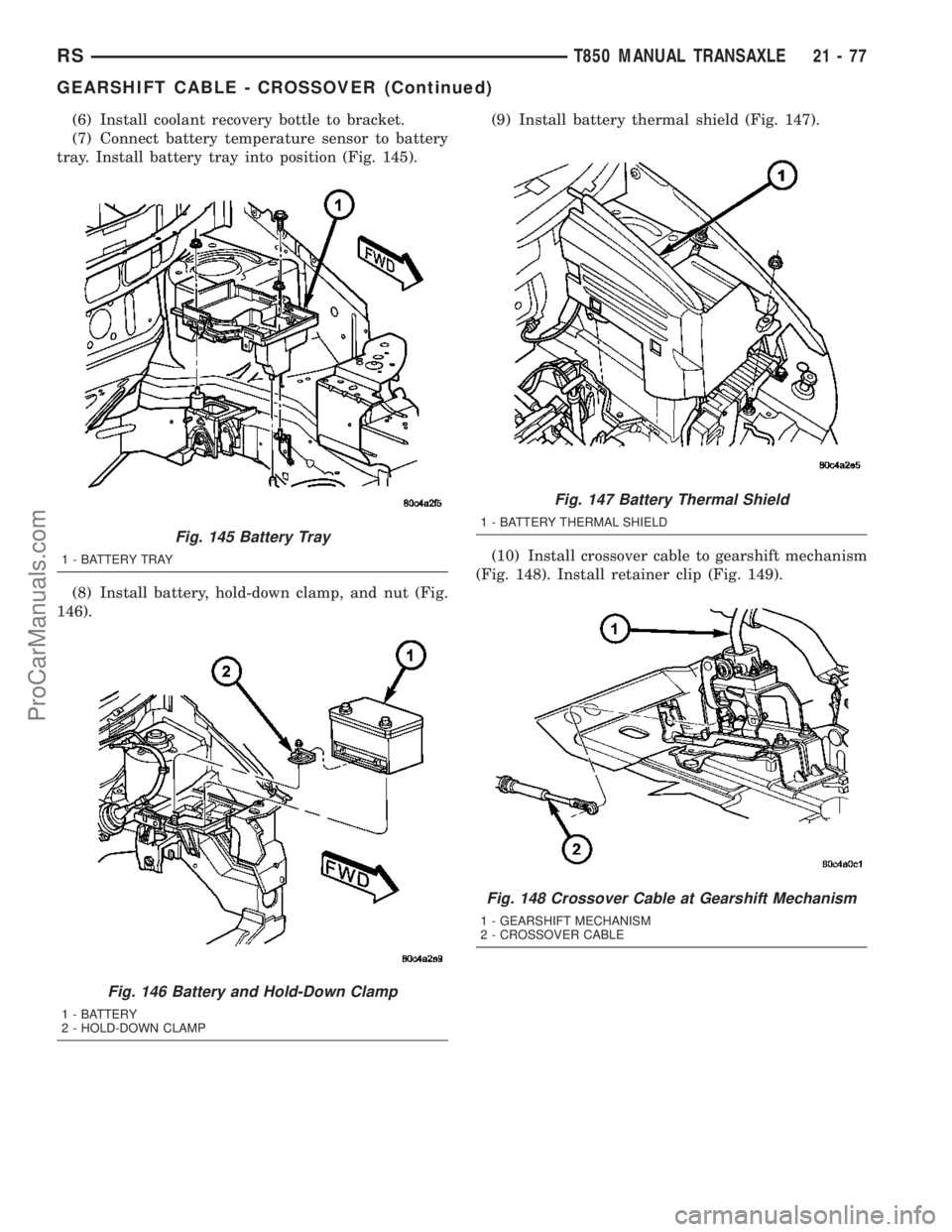
(6) Install coolant recovery bottle to bracket.
(7) Connect battery temperature sensor to battery
tray. Install battery tray into position (Fig. 145).
(8) Install battery, hold-down clamp, and nut (Fig.
146).(9) Install battery thermal shield (Fig. 147).
(10) Install crossover cable to gearshift mechanism
(Fig. 148). Install retainer clip (Fig. 149).
Fig. 145 Battery Tray
1 - BATTERY TRAY
Fig. 146 Battery and Hold-Down Clamp
1 - BATTERY
2 - HOLD-DOWN CLAMP
Fig. 147 Battery Thermal Shield
1 - BATTERY THERMAL SHIELD
Fig. 148 Crossover Cable at Gearshift Mechanism
1 - GEARSHIFT MECHANISM
2 - CROSSOVER CABLE
RST850 MANUAL TRANSAXLE21-77
GEARSHIFT CABLE - CROSSOVER (Continued)
ProCarManuals.com
Page 1530 of 2177
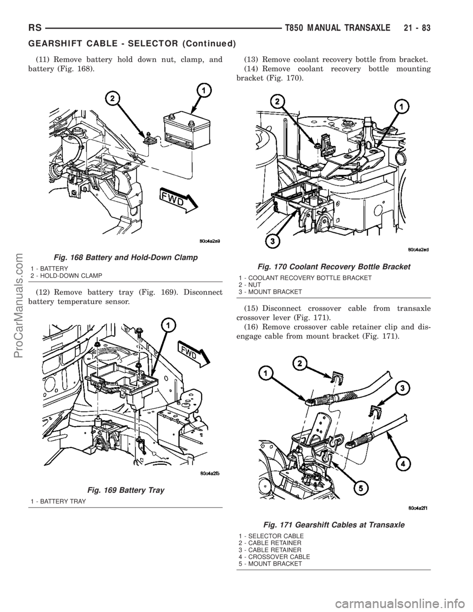
(11) Remove battery hold down nut, clamp, and
battery (Fig. 168).
(12) Remove battery tray (Fig. 169). Disconnect
battery temperature sensor.(13) Remove coolant recovery bottle from bracket.
(14) Remove coolant recovery bottle mounting
bracket (Fig. 170).
(15) Disconnect crossover cable from transaxle
crossover lever (Fig. 171).
(16) Remove crossover cable retainer clip and dis-
engage cable from mount bracket (Fig. 171).
Fig. 168 Battery and Hold-Down Clamp
1 - BATTERY
2 - HOLD-DOWN CLAMP
Fig. 169 Battery Tray
1 - BATTERY TRAY
Fig. 170 Coolant Recovery Bottle Bracket
1 - COOLANT RECOVERY BOTTLE BRACKET
2 - NUT
3 - MOUNT BRACKET
Fig. 171 Gearshift Cables at Transaxle
1 - SELECTOR CABLE
2 - CABLE RETAINER
3 - CABLE RETAINER
4 - CROSSOVER CABLE
5 - MOUNT BRACKET
RST850 MANUAL TRANSAXLE21-83
GEARSHIFT CABLE - SELECTOR (Continued)
ProCarManuals.com
Page 1531 of 2177
(17) Raise vehicle on hoist.
(18) Remove selector cable from engine compart-
ment, then remove cable from passenger compart-
ment through opening in floor pan.
INSTALLATION
(1) From underneath vehicle, install gearshift
selector cable into passenger compartment through
floor pan hole. Install remainder of cable into posi-
tion in engine compartment.
(2) Lower vehicle.
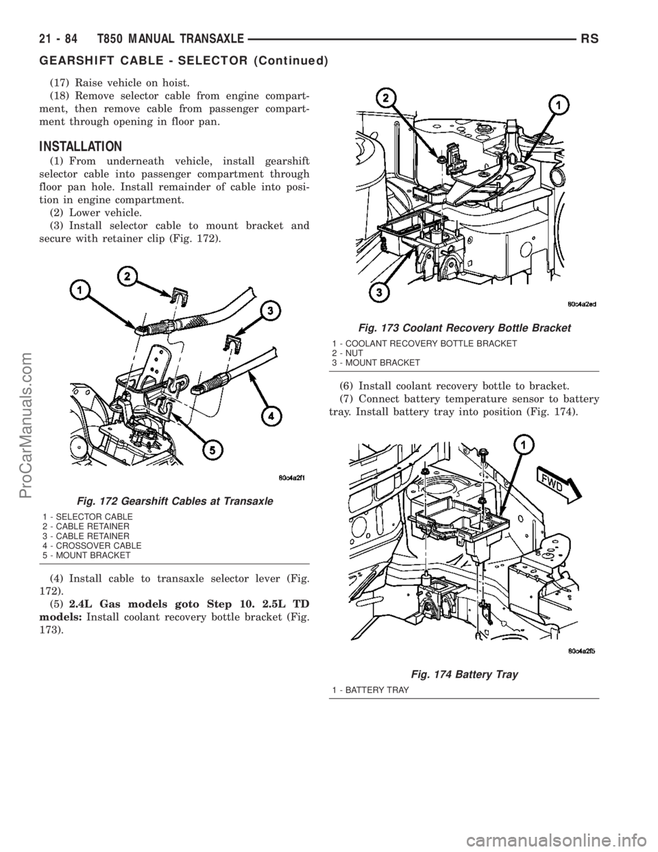
(3) Install selector cable to mount bracket and
secure with retainer clip (Fig. 172).
(4) Install cable to transaxle selector lever (Fig.
172).
(5)2.4L Gas models goto Step 10. 2.5L TD
models:Install coolant recovery bottle bracket (Fig.
173).(6) Install coolant recovery bottle to bracket.
(7) Connect battery temperature sensor to battery
tray. Install battery tray into position (Fig. 174).
Fig. 172 Gearshift Cables at Transaxle
1 - SELECTOR CABLE
2 - CABLE RETAINER
3 - CABLE RETAINER
4 - CROSSOVER CABLE
5 - MOUNT BRACKET
Fig. 173 Coolant Recovery Bottle Bracket
1 - COOLANT RECOVERY BOTTLE BRACKET
2 - NUT
3 - MOUNT BRACKET
Fig. 174 Battery Tray
1 - BATTERY TRAY
21 - 84 T850 MANUAL TRANSAXLERS
GEARSHIFT CABLE - SELECTOR (Continued)
ProCarManuals.com
Page 1562 of 2177
VEHICLE SPEED SENSOR
REMOVAL
(1) Raise vehicle on hoist.
(2)
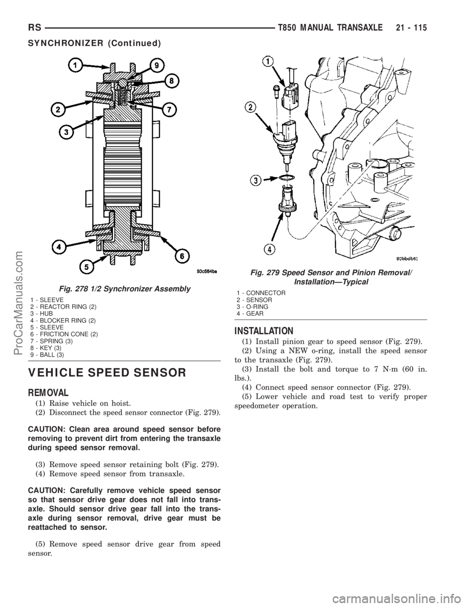
Disconnect the speed sensor connector (Fig. 279).
CAUTION: Clean area around speed sensor before
removing to prevent dirt from entering the transaxle
during speed sensor removal.
(3) Remove speed sensor retaining bolt (Fig. 279).
(4) Remove speed sensor from transaxle.
CAUTION: Carefully remove vehicle speed sensor
so that sensor drive gear does not fall into trans-
axle. Should sensor drive gear fall into the trans-
axle during sensor removal, drive gear must be
reattached to sensor.
(5) Remove speed sensor drive gear from speed
sensor.
INSTALLATION
(1) Install pinion gear to speed sensor (Fig. 279).
(2) Using a NEW o-ring, install the speed sensor
to the transaxle (Fig. 279).
(3) Install the bolt and torque to 7 N´m (60 in.
lbs.).
(4) Connect speed sensor connector (Fig. 279).
(5) Lower vehicle and road test to verify proper
speedometer operation.
Fig. 278 1/2 Synchronizer Assembly
1 - SLEEVE
2 - REACTOR RING (2)
3 - HUB
4 - BLOCKER RING (2)
5 - SLEEVE
6 - FRICTION CONE (2)
7 - SPRING (3)
8 - KEY (3)
9 - BALL (3)
Fig. 279 Speed Sensor and Pinion Removal/
InstallationÐTypical
1 - CONNECTOR
2 - SENSOR
3 - O-RING
4 - GEAR
RST850 MANUAL TRANSAXLE21 - 115
SYNCHRONIZER (Continued)
ProCarManuals.com
Page 1563 of 2177
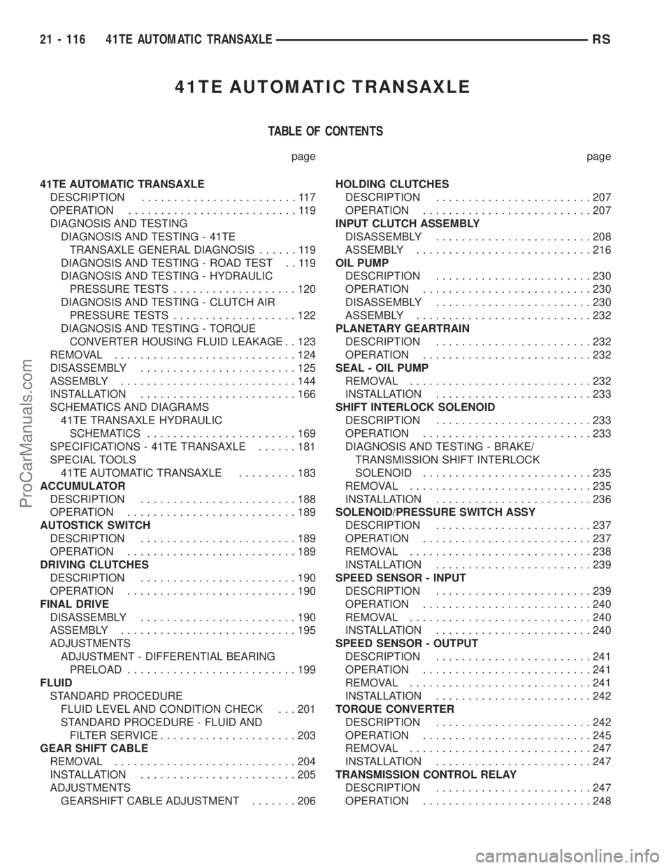
41TE AUTOMATIC TRANSAXLE
TABLE OF CONTENTS
page page
41TE AUTOMATIC TRANSAXLE
DESCRIPTION........................117
OPERATION..........................119
DIAGNOSIS AND TESTING
DIAGNOSIS AND TESTING - 41TE
TRANSAXLE GENERAL DIAGNOSIS......119
DIAGNOSIS AND TESTING - ROAD TEST . . 119
DIAGNOSIS AND TESTING - HYDRAULIC
PRESSURE TESTS...................120
DIAGNOSIS AND TESTING - CLUTCH AIR
PRESSURE TESTS...................122
DIAGNOSIS AND TESTING - TORQUE
CONVERTER HOUSING FLUID LEAKAGE . . 123
REMOVAL............................124
DISASSEMBLY........................125
ASSEMBLY...........................144
INSTALLATION........................166
SCHEMATICS AND DIAGRAMS
41TE TRANSAXLE HYDRAULIC
SCHEMATICS.......................169
SPECIFICATIONS - 41TE TRANSAXLE......181
SPECIAL TOOLS
41TE AUTOMATIC TRANSAXLE.........183
ACCUMULATOR
DESCRIPTION........................188
OPERATION..........................189
AUTOSTICK SWITCH
DESCRIPTION........................189
OPERATION..........................189
DRIVING CLUTCHES
DESCRIPTION........................190
OPERATION..........................190
FINAL DRIVE
DISASSEMBLY........................190
ASSEMBLY...........................195
ADJUSTMENTS
ADJUSTMENT - DIFFERENTIAL BEARING
PRELOAD..........................199
FLUID
STANDARD PROCEDURE
FLUID LEVEL AND CONDITION CHECK . . . 201
STANDARD PROCEDURE - FLUID AND
FILTER SERVICE.....................203
GEAR SHIFT CABLE
REMOVAL............................204
INSTALLATION........................205
ADJUSTMENTS
GEARSHIFT CABLE ADJUSTMENT.......206HOLDING CLUTCHES
DESCRIPTION........................207
OPERATION..........................207
INPUT CLUTCH ASSEMBLY
DISASSEMBLY........................208
ASSEMBLY...........................216
OIL PUMP
DESCRIPTION........................230
OPERATION..........................230
DISASSEMBLY........................230
ASSEMBLY...........................232
PLANETARY GEARTRAIN
DESCRIPTION........................232
OPERATION..........................232
SEAL - OIL PUMP
REMOVAL............................232
INSTALLATION........................233
SHIFT INTERLOCK SOLENOID
DESCRIPTION........................233
OPERATION..........................233
DIAGNOSIS AND TESTING - BRAKE/
TRANSMISSION SHIFT INTERLOCK
SOLENOID..........................235
REMOVAL............................235
INSTALLATION........................236
SOLENOID/PRESSURE SWITCH ASSY
DESCRIPTION........................237
OPERATION..........................237
REMOVAL............................238
INSTALLATION........................239
SPEED SENSOR - INPUT
DESCRIPTION........................239
OPERATION..........................240
REMOVAL............................240
INSTALLATION........................240
SPEED SENSOR - OUTPUT
DESCRIPTION........................241
OPERATION..........................241
REMOVAL............................241
INSTALLATION........................242
TORQUE CONVERTER
DESCRIPTION........................242
OPERATION..........................245
REMOVAL............................247
INSTALLATION........................247
TRANSMISSION CONTROL RELAY
DESCRIPTION........................247
OPERATION..........................248
21 - 116 41TE AUTOMATIC TRANSAXLERS
ProCarManuals.com
Page 1564 of 2177
TRANSMISSION RANGE SENSOR
DESCRIPTION........................248
OPERATION..........................248
REMOVAL............................249
INSTALLATION........................249
TRD LINK
DESCRIPTION........................249
OPERATION..........................249VALVE BODY
DESCRIPTION........................250
OPERATION..........................250
REMOVAL............................251
DISASSEMBLY........................252
ASSEMBLY...........................257
INSTALLATION........................262
41TE AUTOMATIC
TRANSAXLE
DESCRIPTION
The 41TE (Fig. 1) is a four-speed transaxle that is
a conventional hydraulic/mechanical assembly with
an integral differential, and is controlled with adap-
tive electronic controls and monitors. The hydraulic
system of the transaxle consists of the transaxle
fluid, fluid passages, hydraulic valves, and various
line pressure control components. An input clutch
assembly which houses the underdrive, overdrive,
and reverse clutches is used. It also utilizes separate
holding clutches: 2nd/4th gear and Low/Reverse. The
primary mechanical components of the transaxle con-
sist of the following:
²Three multiple disc input clutches
²Two multiple disc holding clutches
²Four hydraulic accumulators
²Two planetary gear sets
²Hydraulic oil pump
²Valve body
²Solenoid/Pressure switch assembly
²Integral differential assemblyControl of the transaxle is accomplished by fully
adaptive electronics. Optimum shift scheduling is
accomplished through continuous real-time sensor
feedback information provided to the Powertrain
Control Module (PCM) or Transmission Control Mod-
ule (TCM).
The PCM/TCM is the heart of the electronic control
system and relies on information from various direct
and indirect inputs (sensors, switches, etc.) to deter-
mine driver demand and vehicle operating condi-
tions. With this information, the PCM/TCM can
calculate and perform timely and quality shifts
through various output or control devices (solenoid
pack, transmission control relay, etc.).
The PCM/TCM also performs certain self-diagnos-
tic functions and provides comprehensive information
(sensor data, DTC's, etc.) which is helpful in proper
diagnosis and repair. This information can be viewed
with the DRB scan tool.
RS41TE AUTOMATIC TRANSAXLE21 - 117
ProCarManuals.com
Page 1565 of 2177
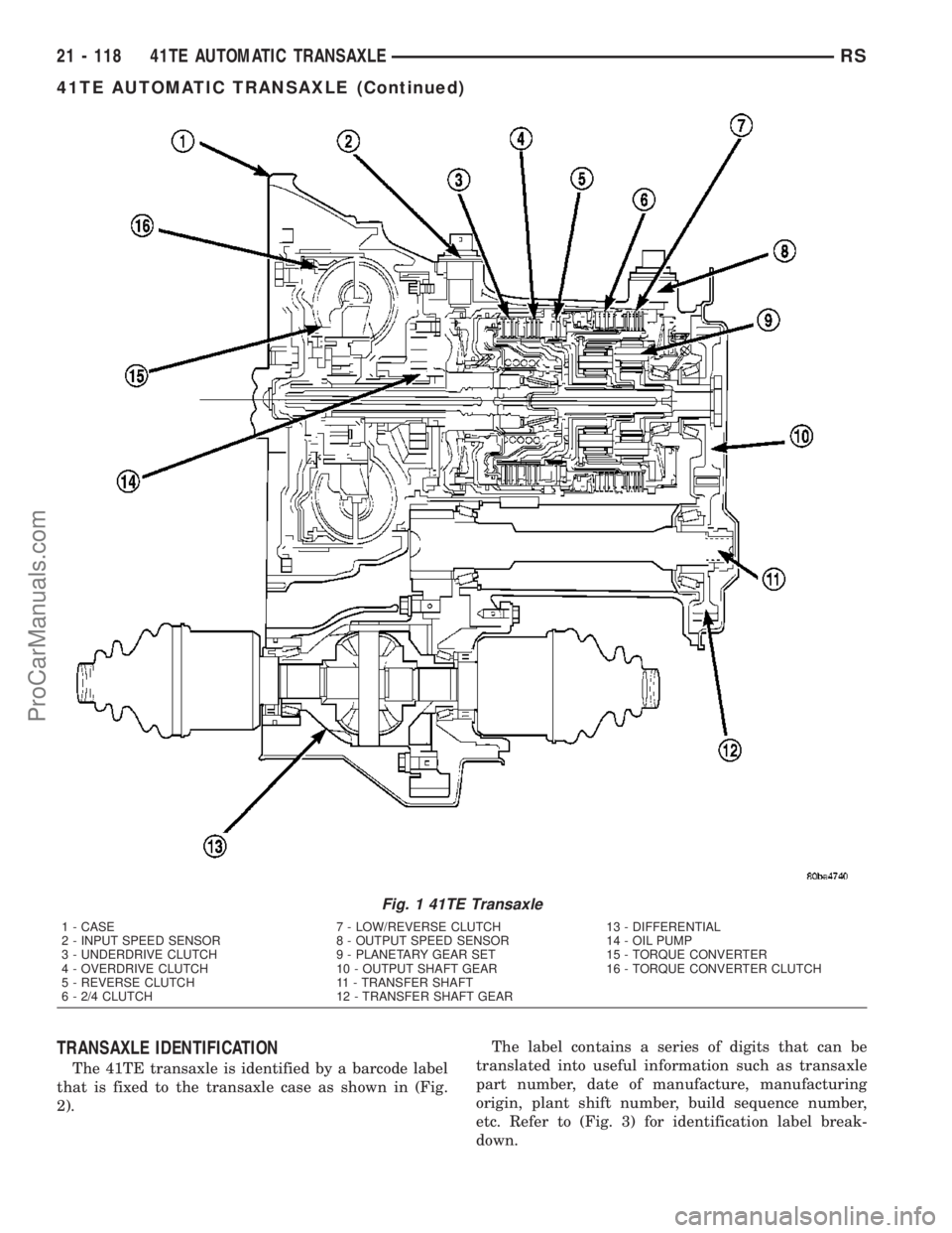
TRANSAXLE IDENTIFICATION
The 41TE transaxle is identified by a barcode label
that is fixed to the transaxle case as shown in (Fig.
2).The label contains a series of digits that can be
translated into useful information such as transaxle
part number, date of manufacture, manufacturing
origin, plant shift number, build sequence number,
etc. Refer to (Fig. 3) for identification label break-
down.
Fig. 1 41TE Transaxle
1 - CASE 7 - LOW/REVERSE CLUTCH 13 - DIFFERENTIAL
2 - INPUT SPEED SENSOR 8 - OUTPUT SPEED SENSOR 14 - OIL PUMP
3 - UNDERDRIVE CLUTCH 9 - PLANETARY GEAR SET 15 - TORQUE CONVERTER
4 - OVERDRIVE CLUTCH 10 - OUTPUT SHAFT GEAR 16 - TORQUE CONVERTER CLUTCH
5 - REVERSE CLUTCH 11 - TRANSFER SHAFT
6 - 2/4 CLUTCH 12 - TRANSFER SHAFT GEAR
21 - 118 41TE AUTOMATIC TRANSAXLERS
41TE AUTOMATIC TRANSAXLE (Continued)
ProCarManuals.com
Page 1571 of 2177
TORQUE CONVERTER LEAKAGE
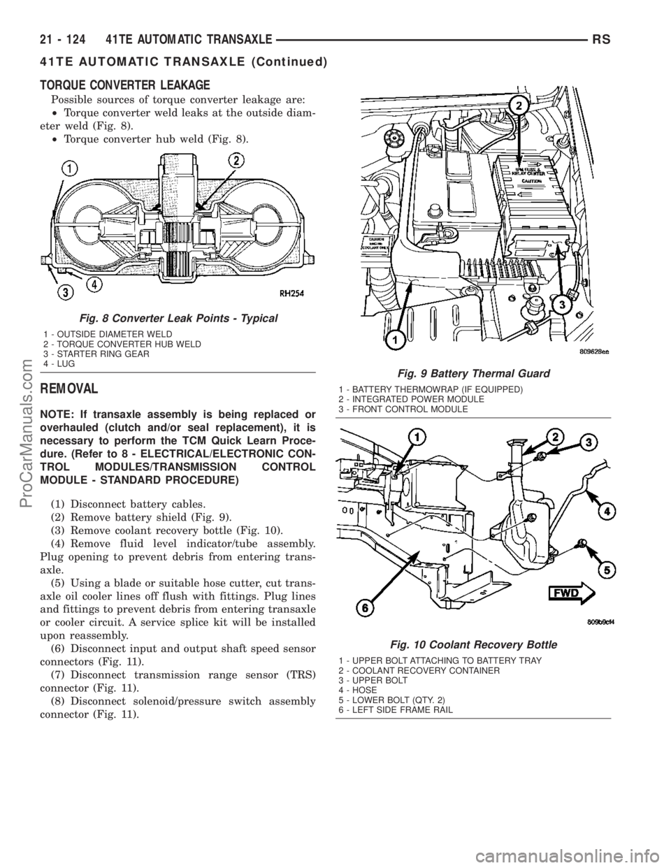
Possible sources of torque converter leakage are:
²Torque converter weld leaks at the outside diam-
eter weld (Fig. 8).
²Torque converter hub weld (Fig. 8).
REMOVAL
NOTE: If transaxle assembly is being replaced or
overhauled (clutch and/or seal replacement), it is
necessary to perform the TCM Quick Learn Proce-
dure. (Refer to 8 - ELECTRICAL/ELECTRONIC CON-
TROL MODULES/TRANSMISSION CONTROL
MODULE - STANDARD PROCEDURE)
(1) Disconnect battery cables.
(2) Remove battery shield (Fig. 9).
(3) Remove coolant recovery bottle (Fig. 10).
(4) Remove fluid level indicator/tube assembly.
Plug opening to prevent debris from entering trans-
axle.
(5) Using a blade or suitable hose cutter, cut trans-
axle oil cooler lines off flush with fittings. Plug lines
and fittings to prevent debris from entering transaxle
or cooler circuit. A service splice kit will be installed
upon reassembly.
(6) Disconnect input and output shaft speed sensor
connectors (Fig. 11).
(7) Disconnect transmission range sensor (TRS)
connector (Fig. 11).
(8) Disconnect solenoid/pressure switch assembly
connector (Fig. 11).
Fig. 8 Converter Leak Points - Typical
1 - OUTSIDE DIAMETER WELD
2 - TORQUE CONVERTER HUB WELD
3 - STARTER RING GEAR
4 - LUG
Fig. 9 Battery Thermal Guard
1 - BATTERY THERMOWRAP (IF EQUIPPED)
2 - INTEGRATED POWER MODULE
3 - FRONT CONTROL MODULE
Fig. 10 Coolant Recovery Bottle
1 - UPPER BOLT ATTACHING TO BATTERY TRAY
2 - COOLANT RECOVERY CONTAINER
3 - UPPER BOLT
4 - HOSE
5 - LOWER BOLT (QTY. 2)
6 - LEFT SIDE FRAME RAIL
21 - 124 41TE AUTOMATIC TRANSAXLERS
41TE AUTOMATIC TRANSAXLE (Continued)
ProCarManuals.com