Page 1450 of 2177
OPERATION
The Transfer Unit provides the power to the rear
wheels through a hypoid ring gear and pinion set.
DIAGNOSIS AND TESTING
SEAL IDENTIFICATION
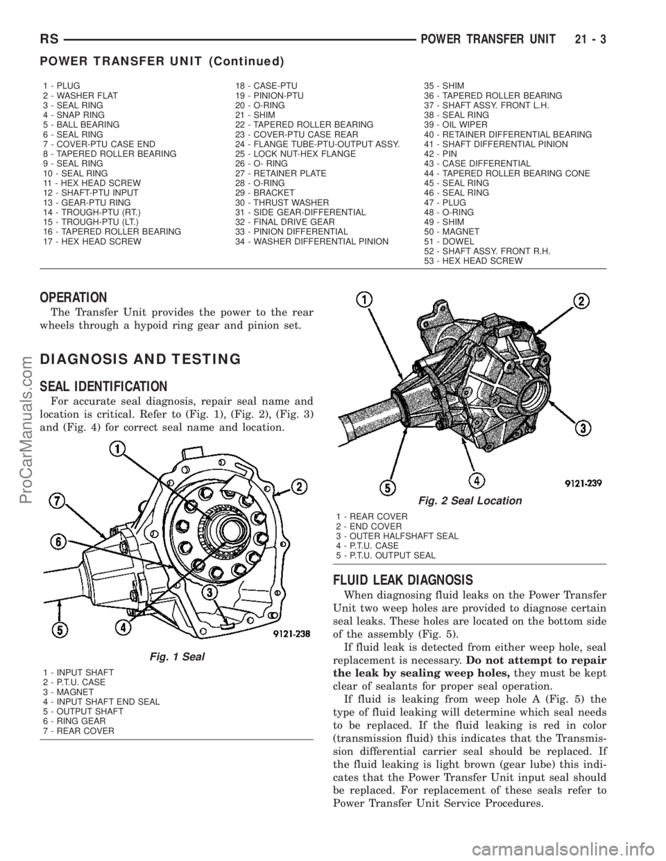
For accurate seal diagnosis, repair seal name and
location is critical. Refer to (Fig. 1), (Fig. 2), (Fig. 3)
and (Fig. 4) for correct seal name and location.
FLUID LEAK DIAGNOSIS
When diagnosing fluid leaks on the Power Transfer
Unit two weep holes are provided to diagnose certain
seal leaks. These holes are located on the bottom side
of the assembly (Fig. 5).
If fluid leak is detected from either weep hole, seal
replacement is necessary.Do not attempt to repair
the leak by sealing weep holes,they must be kept
clear of sealants for proper seal operation.
If fluid is leaking from weep hole A (Fig. 5) the
type of fluid leaking will determine which seal needs
to be replaced. If the fluid leaking is red in color
(transmission fluid) this indicates that the Transmis-
sion differential carrier seal should be replaced. If
the fluid leaking is light brown (gear lube) this indi-
cates that the Power Transfer Unit input seal should
be replaced. For replacement of these seals refer to
Power Transfer Unit Service Procedures.
1 - PLUG 18 - CASE-PTU 35 - SHIM
2 - WASHER FLAT 19 - PINION-PTU 36 - TAPERED ROLLER BEARING
3 - SEAL RING 20 - O-RING 37 - SHAFT ASSY. FRONT L.H.
4 - SNAP RING 21 - SHIM 38 - SEAL RING
5 - BALL BEARING 22 - TAPERED ROLLER BEARING 39 - OIL WIPER
6 - SEAL RING 23 - COVER-PTU CASE REAR 40 - RETAINER DIFFERENTIAL BEARING
7 - COVER-PTU CASE END 24 - FLANGE TUBE-PTU-OUTPUT ASSY. 41 - SHAFT DIFFERENTIAL PINION
8 - TAPERED ROLLER BEARING 25 - LOCK NUT-HEX FLANGE 42 - PIN
9 - SEAL RING 26 - O- RING 43 - CASE DIFFERENTIAL
10 - SEAL RING 27 - RETAINER PLATE 44 - TAPERED ROLLER BEARING CONE
11 - HEX HEAD SCREW 28 - O-RING 45 - SEAL RING
12 - SHAFT-PTU INPUT 29 - BRACKET 46 - SEAL RING
13 - GEAR-PTU RING 30 - THRUST WASHER 47 - PLUG
14 - TROUGH-PTU (RT.) 31 - SIDE GEAR-DIFFERENTIAL 48 - O-RING
15 - TROUGH-PTU (LT.) 32 - FINAL DRIVE GEAR 49 - SHIM
16 - TAPERED ROLLER BEARING 33 - PINION DIFFERENTIAL 50 - MAGNET
17 - HEX HEAD SCREW 34 - WASHER DIFFERENTIAL PINION 51 - DOWEL
52 - SHAFT ASSY. FRONT R.H.
53 - HEX HEAD SCREW
Fig. 1 Seal
1 - INPUT SHAFT
2 - P.T.U. CASE
3 - MAGNET
4 - INPUT SHAFT END SEAL
5 - OUTPUT SHAFT
6 - RING GEAR
7 - REAR COVER
Fig. 2 Seal Location
1 - REAR COVER
2 - END COVER
3 - OUTER HALFSHAFT SEAL
4 - P.T.U. CASE
5 - P.T.U. OUTPUT SEAL
RSPOWER TRANSFER UNIT21-3
POWER TRANSFER UNIT (Continued)
ProCarManuals.com
Page 1451 of 2177
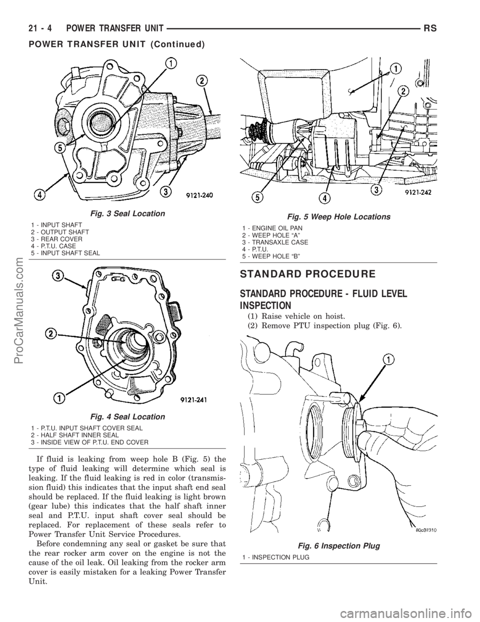
If fluid is leaking from weep hole B (Fig. 5) the
type of fluid leaking will determine which seal is
leaking. If the fluid leaking is red in color (transmis-
sion fluid) this indicates that the input shaft end seal
should be replaced. If the fluid leaking is light brown
(gear lube) this indicates that the half shaft inner
seal and P.T.U. input shaft cover seal should be
replaced. For replacement of these seals refer to
Power Transfer Unit Service Procedures.
Before condemning any seal or gasket be sure that
the rear rocker arm cover on the engine is not the
cause of the oil leak. Oil leaking from the rocker arm
cover is easily mistaken for a leaking Power Transfer
Unit.
STANDARD PROCEDURE
STANDARD PROCEDURE - FLUID LEVEL
INSPECTION
(1) Raise vehicle on hoist.
(2) Remove PTU inspection plug (Fig. 6).
Fig. 3 Seal Location
1 - INPUT SHAFT
2 - OUTPUT SHAFT
3 - REAR COVER
4 - P.T.U. CASE
5 - INPUT SHAFT SEAL
Fig. 4 Seal Location
1 - P.T.U. INPUT SHAFT COVER SEAL
2 - HALF SHAFT INNER SEAL
3 - INSIDE VIEW OF P.T.U. END COVER
Fig. 5 Weep Hole Locations
1 - ENGINE OIL PAN
2 - WEEP HOLE ªAº
3 - TRANSAXLE CASE
4 - P.T.U.
5 - WEEP HOLE ªBº
Fig. 6 Inspection Plug
1 - INSPECTION PLUG
21 - 4 POWER TRANSFER UNITRS
POWER TRANSFER UNIT (Continued)
ProCarManuals.com
Page 1460 of 2177
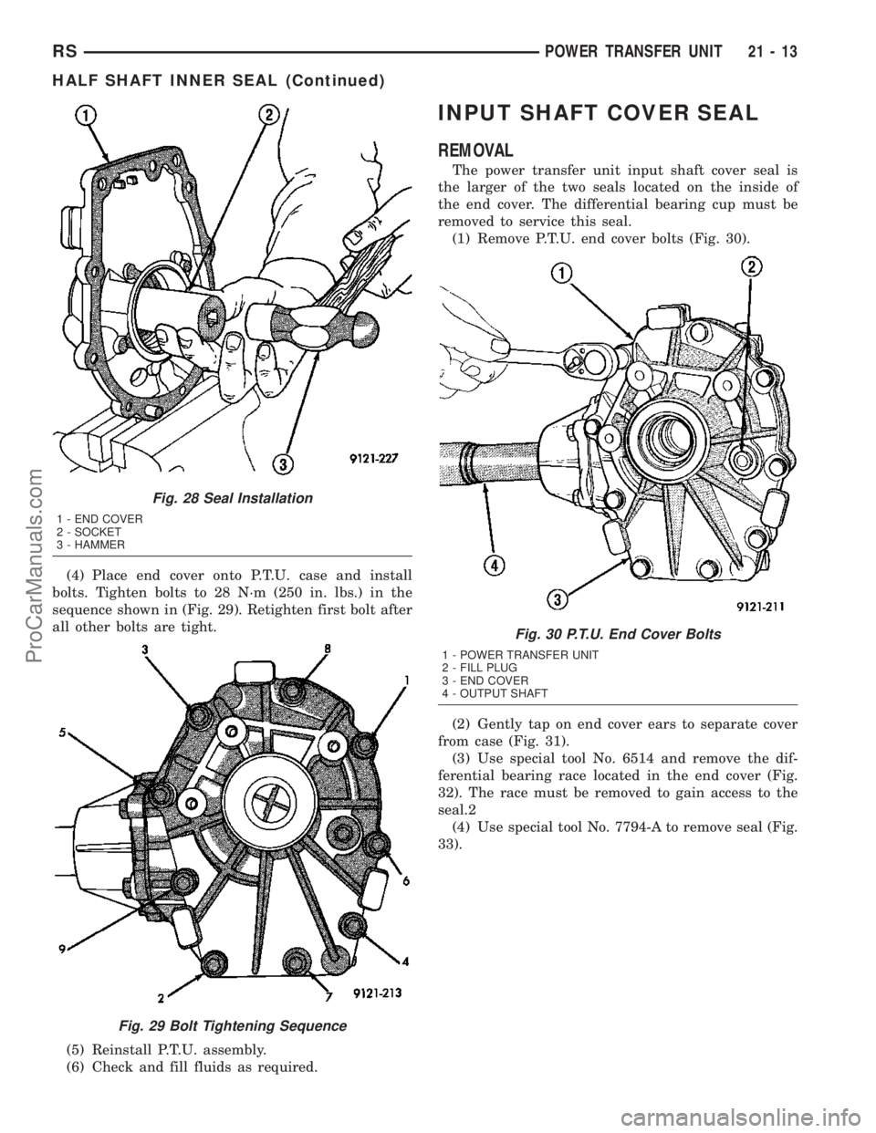
(4) Place end cover onto P.T.U. case and install
bolts. Tighten bolts to 28 N´m (250 in. lbs.) in the
sequence shown in (Fig. 29). Retighten first bolt after
all other bolts are tight.
(5) Reinstall P.T.U. assembly.
(6) Check and fill fluids as required.
INPUT SHAFT COVER SEAL
REMOVAL
The power transfer unit input shaft cover seal is
the larger of the two seals located on the inside of
the end cover. The differential bearing cup must be
removed to service this seal.
(1) Remove P.T.U. end cover bolts (Fig. 30).
(2) Gently tap on end cover ears to separate cover
from case (Fig. 31).
(3) Use special tool No. 6514 and remove the dif-
ferential bearing race located in the end cover (Fig.
32). The race must be removed to gain access to the
seal.2
(4) Use special tool No. 7794-A to remove seal (Fig.
33).
Fig. 28 Seal Installation
1 - END COVER
2 - SOCKET
3 - HAMMER
Fig. 29 Bolt Tightening Sequence
Fig. 30 P.T.U. End Cover Bolts
1 - POWER TRANSFER UNIT
2 - FILL PLUG
3 - END COVER
4 - OUTPUT SHAFT
RSPOWER TRANSFER UNIT21-13
HALF SHAFT INNER SEAL (Continued)
ProCarManuals.com
Page 1461 of 2177
INSTALLATION
The power transfer unit input shaft cover seal is
the larger of the two seals located on the inside of
the end cover. The differential bearing cup must be
removed to service this seal.
(1) Clean and inspect seal area.
(2) Use special tool No. MD998803 and install seal
(Fig. 34). When installing seal the spring side of the
seal must face toward the special tool.
Fig. 31 End Cover Removal
1 - END COVER EARS
2 - HAMMER
3 - POWER TRANSFER UNIT
Fig. 32 Bearing Race Removal
1 - END COVER
2 - SPECIAL TOOL
No. 6514
Fig. 33 Seal Removal
1 - END COVER
2 - SPECIAL TOOL
7794±A
3 - SLIDE HAMMER
4 - SOFT JAW VICE
Fig. 34 Seal Installation
1 - SPECIAL TOOL No. MD998803
2 - HAMMER
3 - END COVER
21 - 14 POWER TRANSFER UNITRS
INPUT SHAFT COVER SEAL (Continued)
ProCarManuals.com
Page 1464 of 2177
INPUT SHAFT SEAL
REMOVAL
The Power Transfer Unit must be removed from
the vehicle to service this seal. Refer to Power Trans-
fer Unit Removal in this section for procedures.
(1) Remove P.T.U. end cover bolts (Fig. 42).
(2) Gently tap on end cover ears to separate cover
from case (Fig. 43).
(3) Remove ring gear oil trough (Fig. 44).
(4) Remove input shaft and ring gear from case
(Fig. 45).
(5) Use Special Tool No. 7794-A (seal puller) to
remove seal (Fig. 46).
Fig. 42 P.T.U. End Cover Bolts
1 - POWER TRANSFER UNIT
2 - FILL PLUG
3 - END COVER
4 - OUTPUT SHAFT
Fig. 43 End Cover Removal
1 - END COVER EARS
2 - HAMMER
3 - POWER TRANSFER UNIT
Fig. 44 Oil Trough
1 - OIL TROUGH
2 - POWER TRANSFER UNIT
RSPOWER TRANSFER UNIT21-17
ProCarManuals.com
Page 1465 of 2177
INSTALLATION
The Power Transfer Unit must be removed from
the vehicle to service this seal. Refer to Power Trans-
fer Unit Removal in this section for procedures.
(1) Clean and inspect seal area.
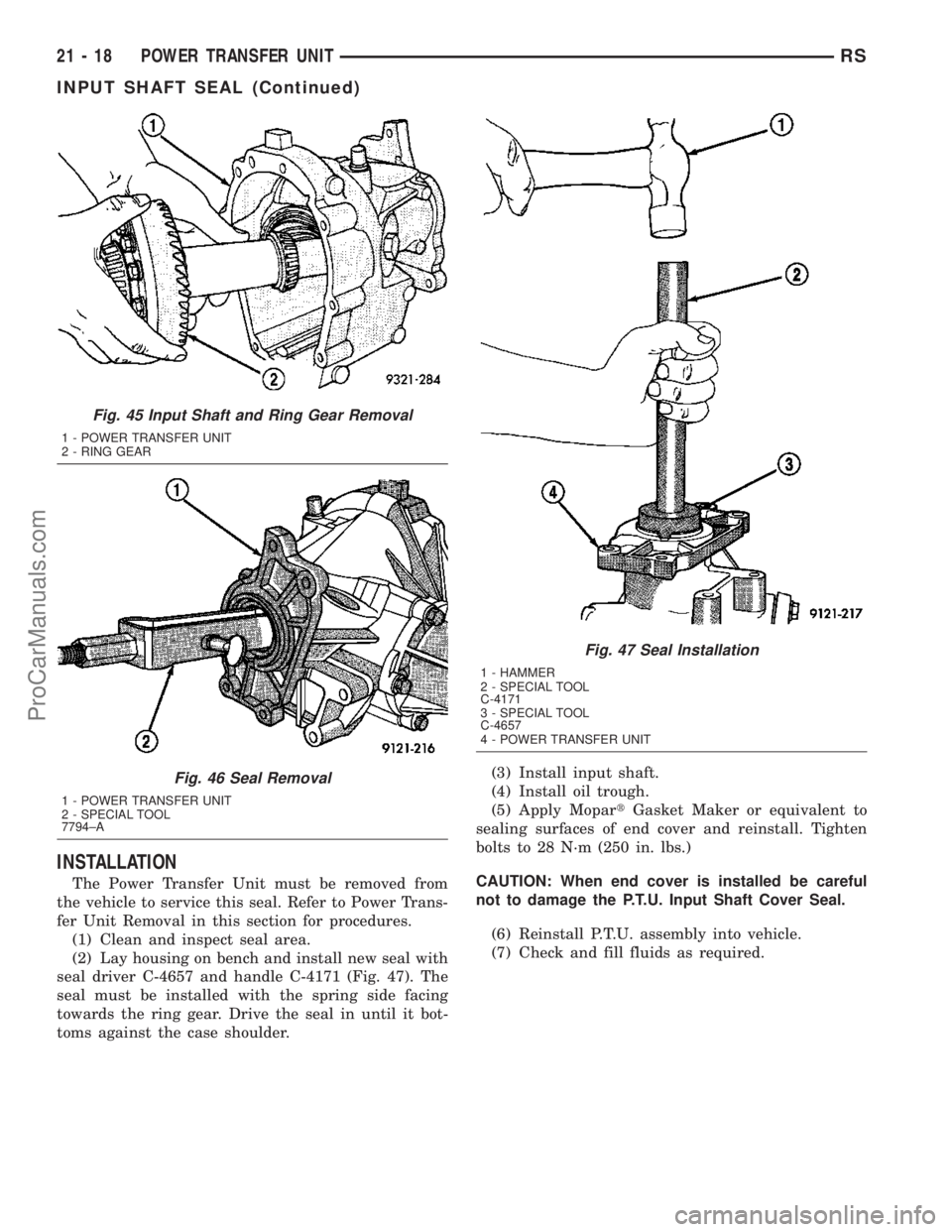
(2) Lay housing on bench and install new seal with
seal driver C-4657 and handle C-4171 (Fig. 47). The
seal must be installed with the spring side facing
towards the ring gear. Drive the seal in until it bot-
toms against the case shoulder.(3) Install input shaft.
(4) Install oil trough.
(5) Apply MopartGasket Maker or equivalent to
sealing surfaces of end cover and reinstall. Tighten
bolts to 28 N´m (250 in. lbs.)
CAUTION: When end cover is installed be careful
not to damage the P.T.U. Input Shaft Cover Seal.
(6) Reinstall P.T.U. assembly into vehicle.
(7) Check and fill fluids as required.
Fig. 45 Input Shaft and Ring Gear Removal
1 - POWER TRANSFER UNIT
2 - RING GEAR
Fig. 46 Seal Removal
1 - POWER TRANSFER UNIT
2 - SPECIAL TOOL
7794±A
Fig. 47 Seal Installation
1 - HAMMER
2 - SPECIAL TOOL
C-4171
3 - SPECIAL TOOL
C-4657
4 - POWER TRANSFER UNIT
21 - 18 POWER TRANSFER UNITRS
INPUT SHAFT SEAL (Continued)
ProCarManuals.com
Page 1470 of 2177
The NV T850 transaxle is available with the 2.4L
Gas and 2.5L Turbo Diesel engine options. Unique
gearing tailored to the performance characteristics of
each engine provides optimum driveability, gradabil-
ity, and acceleration. The gear ratios are as follows:
GEARRATIO (2.4L
Gas)RATIO (2.5L
TD)
1st 3.65 3.65
2nd 2.05 2.05
3rd 1.39 1.37
4th 1.03 0.97
5th 0.83 0.76
Reverse 3.47 3.47
Final Drive
Ratio3.77 3.77
Overall Top
Gear3.12 2.67
TRANSAXLE IDENTIFICATION
NOTE: Since transaxles use unique gear ratios for
each of the two engine applications, it is imperative
that the transaxle is properly identified, and the cor-
rect transaxle assembly number is used when
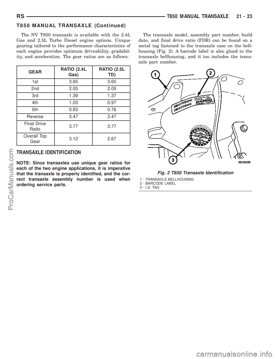
ordering service parts.The transaxle model, assembly part number, build
date, and final drive ratio (FDR) can be found on a
metal tag fastened to the transaxle case on the bell-
housing (Fig. 2). A barcode label is also glued to the
transaxle bellhousing, and it too includes the trans-
axle part number.
Fig. 2 T850 Transaxle Identification
1 - TRANSAXLE BELLHOUSING
2 - BARCODE LABEL
3 - I.D. TAG
RST850 MANUAL TRANSAXLE21-23
T850 MANUAL TRANSAXLE (Continued)
ProCarManuals.com
Page 1547 of 2177
INTERMEDIATE SHAFT
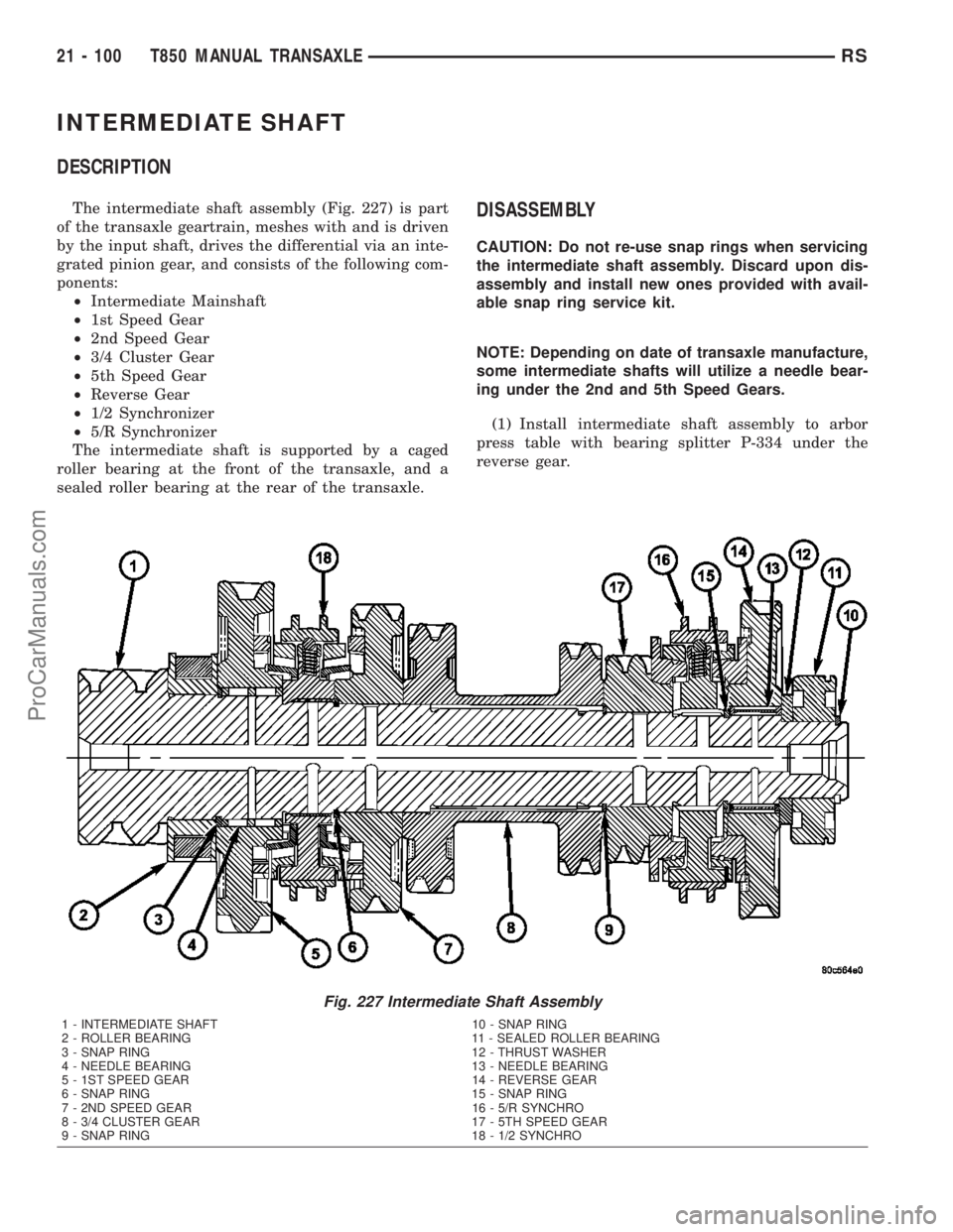
DESCRIPTION
The intermediate shaft assembly (Fig. 227) is part
of the transaxle geartrain, meshes with and is driven
by the input shaft, drives the differential via an inte-
grated pinion gear, and consists of the following com-
ponents:
²Intermediate Mainshaft
²1st Speed Gear
²2nd Speed Gear
²3/4 Cluster Gear
²5th Speed Gear
²Reverse Gear
²1/2 Synchronizer
²5/R Synchronizer
The intermediate shaft is supported by a caged
roller bearing at the front of the transaxle, and a
sealed roller bearing at the rear of the transaxle.DISASSEMBLY
CAUTION: Do not re-use snap rings when servicing
the intermediate shaft assembly. Discard upon dis-
assembly and install new ones provided with avail-
able snap ring service kit.
NOTE: Depending on date of transaxle manufacture,
some intermediate shafts will utilize a needle bear-
ing under the 2nd and 5th Speed Gears.
(1) Install intermediate shaft assembly to arbor
press table with bearing splitter P-334 under the
reverse gear.
Fig. 227 Intermediate Shaft Assembly
1 - INTERMEDIATE SHAFT 10 - SNAP RING
2 - ROLLER BEARING 11 - SEALED ROLLER BEARING
3 - SNAP RING 12 - THRUST WASHER
4 - NEEDLE BEARING 13 - NEEDLE BEARING
5 - 1ST SPEED GEAR 14 - REVERSE GEAR
6 - SNAP RING 15 - SNAP RING
7 - 2ND SPEED GEAR 16 - 5/R SYNCHRO
8 - 3/4 CLUSTER GEAR 17 - 5TH SPEED GEAR
9 - SNAP RING 18 - 1/2 SYNCHRO
21 - 100 T850 MANUAL TRANSAXLERS
ProCarManuals.com