2003 CHRYSLER VOYAGER Low fuel indicator
[x] Cancel search: Low fuel indicatorPage 589 of 2177

Component Page
Leak Detection Pump................... 8W-30
License Lamp...................... 8W-51, 61
Lift Pump Motor....................... 8W-30
Lift Pump Relay....................... 8W-30
Liftgate Ajar Switch.................. 8W-39, 61
Liftgate Cinch/Release Motor.............. 8W-61
Liftgate Cylinder Lock Switch............. 8W-39
Liftgate Flood Lamps................... 8W-44
Liftgate Left Pinch Sensor................ 8W-61
Liftgate Right Pinch Sensor............... 8W-61
Low Beam Lamps...................... 8W-50
Manifold Absolute Pressure Sensor......... 8W-30
Mass Air Flow Sensor................... 8W-30
Memory Seat/Mirror Module............ 8W-62, 63
Memory Set Switch..................... 8W-63
Message Center........................ 8W-46
Mid Reading Lamps.................... 8W-44
Mode Door Actuator..................... 8W-42
Multi-Function Switch............. 8W-50, 52, 53
Name Brand Speaker Relay............... 8W-47
Natural Vacuum Leak Detection Assembly.... 8W-30
Output Speed Sensor.................... 8W-31
Overhead Console................... 8W-43, 49
Oxygen Sensors........................ 8W-30
Park Lamp Relay...................... 8W-10
Park Lamps.......................... 8W-50
Park/Turn Signal Lamps................. 8W-50
Parking Brake Switch................... 8W-40
Passenger Airbag...................... 8W-43
Passenger Folding Mirror Relay............ 8W-62
Power Folding Mirror Switch.............. 8W-62
Power Liftgate Module.................. 8W-61
Power Liftgate Motor.................... 8W-61
Power Mirror Switch.................... 8W-62
Power Mirrors......................... 8W-62
Power Outlet.......................... 8W-41
Power Seat Circuit Breaker............... 8W-10
Power Seat Front Riser Motors............ 8W-63
Power Seat Front Riser Position Sensors..... 8W-63
Power Seat Horizontal Motors............. 8W-63
Power Seat Horizontal Position Sensors...... 8W-63
Power Seat Rear Riser Motors............. 8W-63
Power Seat Rear Riser Position Sensors...... 8W-63
Power Seat Recliner Motors............... 8W-63
Power Seat Recliner Position Sensors........ 8W-63
Power Seat Switches.................... 8W-63
Power Window Circuit Breaker............ 8W-10
Power Window Motor................... 8W-60
Power Window Switch................... 8W-60
Powertrain Control Module............... 8W-30
PTC's............................... 8W-10
Radiator Fans......................... 8W-42
Radiator Fan Relays.................... 8W-42
Radio............................... 8W-47
Reading Lamps........................ 8W-44
Rear A/C-Heater Unit................... 8W-42
Component Page
Rear Auto Temp Control Switch............ 8W-42
Rear Blower Front Control Switch.......... 8W-42
Rear Blower Motor Power Module.......... 8W-42
Rear Blower Motor Relay................. 8W-42
Rear Blower Motor..................... 8W-42
Rear Blower Rear Control Switch........... 8W-42
Rear Dome Lamp...................... 8W-44
Rear Intrusion Sensor................... 8W-39
Rear Mode Motor...................... 8W-42
Rear Power Outlet...................... 8W-41
Rear Temperature Motor................. 8W-42
Rear Washer Pump Motor................ 8W-53
Rear Window Defogger Grid............... 8W-48
Rear Wiper Motor...................... 8W-53
Recirculation Door Actuator............... 8W-42
Remote Keyless Entry Antenna............ 8W-61
Remote Keyless Entry Module............. 8W-61
Remote Radio Switches.................. 8W-47
Repeater Lamps....................... 8W-52
Splices.............................. 8W-70
Seat Airbags.......................... 8W-43
Seat Belt Tensioner..................... 8W-43
Sentry Key Immobilizer Module............ 8W-39
Side Impact Airbag Control Modules........ 8W-43
Siren............................... 8W-39
Sliding Door Control Modules........... 8W-43, 61
Sliding Door Latch Sensing Switches........ 8W-61
Sliding Door Lock Motors................ 8W-61
Sliding Door Lock Motor/Ajar Switches...... 8W-61
Sliding Door Motors.................... 8W-61
Solenoid/Pressure Switch Assy............. 8W-31
Speakers............................. 8W-47
Speed Control Servo.................... 8W-33
Speed Control Switches.................. 8W-33
Starter Motor Relay.................... 8W-21
Starter Motor......................... 8W-21
Stop/Turn Signal Relays................. 8W-54
Sunroof Module........................ 8W-64
Sunroof Switch........................ 8W-64
Thatcham Alarm Indicator................ 8W-39
Thatcham Alarm Module................. 8W-39
Throttle Position Sensor................. 8W-30
Traction Control Switch.................. 8W-35
Trailer Tow Connector................... 8W-54
Transmission Control Module.............. 8W-31
Transmission Control Relay............... 8W-31
Transmission Range Sensor............... 8W-31
Turn Signal Lamps..................... 8W-52
Vehicle Speed Sensor.................... 8W-30
Vent Motors.......................... 8W-60
Visor/Vanity Lamps..................... 8W-44
Washer Fluid Level Switch............... 8W-53
Water In Fuel Sensor................... 8W-30
Wheel Speed Sensors.................... 8W-35
8W - 02 - 2 8W-02 COMPONENT INDEXRS
ProCarManuals.com
Page 1053 of 2177
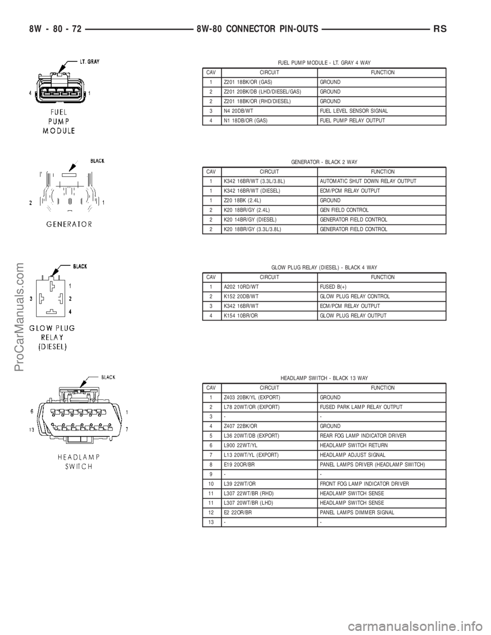
FUEL PUMP MODULE - LT. GRAY 4 WAY
CAV CIRCUIT FUNCTION
1 Z201 18BK/OR (GAS) GROUND
2 Z201 20BK/DB (LHD/DIESEL/GAS) GROUND
2 Z201 18BK/OR (RHD/DIESEL) GROUND
3 N4 20DB/WT FUEL LEVEL SENSOR SIGNAL
4 N1 18DB/OR (GAS) FUEL PUMP RELAY OUTPUT
GENERATOR - BLACK 2 WAY
CAV CIRCUIT FUNCTION
1 K342 16BR/WT (3.3L/3.8L) AUTOMATIC SHUT DOWN RELAY OUTPUT
1 K342 16BR/WT (DIESEL) ECM/PCM RELAY OUTPUT
1 Z20 18BK (2.4L) GROUND
2 K20 18BR/GY (2.4L) GEN FIELD CONTROL
2 K20 14BR/GY (DIESEL) GENERATOR FIELD CONTROL
2 K20 18BR/GY (3.3L/3.8L) GENERATOR FIELD CONTROL
GLOW PLUG RELAY (DIESEL) - BLACK 4 WAY
CAV CIRCUIT FUNCTION
1 A202 10RD/WT FUSED B(+)
2 K152 20DB/WT GLOW PLUG RELAY CONTROL
3 K342 16BR/WT ECM/PCM RELAY OUTPUT
4 K154 10BR/OR GLOW PLUG RELAY OUTPUT
HEADLAMP SWITCH - BLACK 13 WAY
CAV CIRCUIT FUNCTION
1 Z403 20BK/YL (EXPORT) GROUND
2 L78 20WT/OR (EXPORT) FUSED PARK LAMP RELAY OUTPUT
3- -
4 Z407 22BK/OR GROUND
5 L36 20WT/DB (EXPORT) REAR FOG LAMP INDICATOR DRIVER
6 L900 22WT/YL HEADLAMP SWITCH RETURN
7 L13 20WT/YL (EXPORT) HEADLAMP ADJUST SIGNAL
8 E19 20OR/BR PANEL LAMPS DRIVER (HEADLAMP SWITCH)
9- -
10 L39 22WT/OR FRONT FOG LAMP INDICATOR DRIVER
11 L307 22WT/BR (RHD) HEADLAMP SWITCH SENSE
11 L307 20WT/BR (LHD) HEADLAMP SWITCH SENSE
12 E2 22OR/BR PANEL LAMPS DIMMER SIGNAL
13 - -
8W - 80 - 72 8W-80 CONNECTOR PIN-OUTSRS
ProCarManuals.com
Page 1341 of 2177
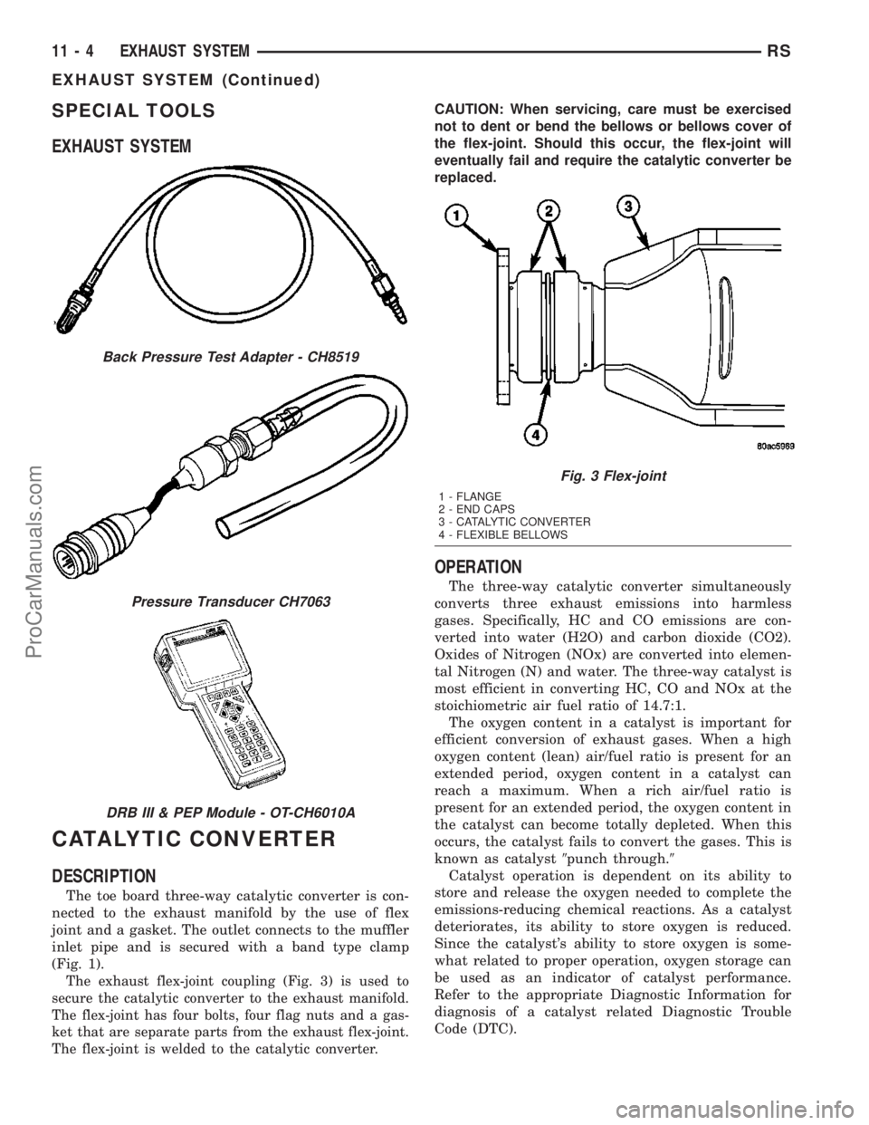
SPECIAL TOOLS
EXHAUST SYSTEM
CATALYTIC CONVERTER
DESCRIPTION
The toe board three-way catalytic converter is con-
nected to the exhaust manifold by the use of flex
joint and a gasket. The outlet connects to the muffler
inlet pipe and is secured with a band type clamp
(Fig. 1).
The exhaust flex-joint coupling (Fig. 3) is used to
secure the catalytic converter to the exhaust manifold.
The flex-joint has four bolts, four flag nuts and a gas-
ket that are separate parts from the exhaust flex-joint.
The flex-joint is welded to the catalytic converter.
CAUTION: When servicing, care must be exercised
not to dent or bend the bellows or bellows cover of
the flex-joint. Should this occur, the flex-joint will
eventually fail and require the catalytic converter be
replaced.
OPERATION
The three-way catalytic converter simultaneously
converts three exhaust emissions into harmless
gases. Specifically, HC and CO emissions are con-
verted into water (H2O) and carbon dioxide (CO2).
Oxides of Nitrogen (NOx) are converted into elemen-
tal Nitrogen (N) and water. The three-way catalyst is
most efficient in converting HC, CO and NOx at the
stoichiometric air fuel ratio of 14.7:1.
The oxygen content in a catalyst is important for
efficient conversion of exhaust gases. When a high
oxygen content (lean) air/fuel ratio is present for an
extended period, oxygen content in a catalyst can
reach a maximum. When a rich air/fuel ratio is
present for an extended period, the oxygen content in
the catalyst can become totally depleted. When this
occurs, the catalyst fails to convert the gases. This is
known as catalyst9punch through.9
Catalyst operation is dependent on its ability to
store and release the oxygen needed to complete the
emissions-reducing chemical reactions. As a catalyst
deteriorates, its ability to store oxygen is reduced.
Since the catalyst's ability to store oxygen is some-
what related to proper operation, oxygen storage can
be used as an indicator of catalyst performance.
Refer to the appropriate Diagnostic Information for
diagnosis of a catalyst related Diagnostic Trouble
Code (DTC).
Back Pressure Test Adapter - CH8519
Pressure Transducer CH7063
DRB III & PEP Module - OT-CH6010A
Fig. 3 Flex-joint
1 - FLANGE
2 - END CAPS
3 - CATALYTIC CONVERTER
4 - FLEXIBLE BELLOWS
11 - 4 EXHAUST SYSTEMRS
EXHAUST SYSTEM (Continued)
ProCarManuals.com
Page 1378 of 2177
1 second. Therefore, battery voltage is not supplied to
the fuel pump, ignition coil, fuel injectors and heated
oxygen sensors.
ENGINE START-UP MODE
This is an OPEN LOOP mode. If the vehicle is in
park or neutral (automatic transaxles) or the clutch
pedal is depressed (manual transaxles) the ignition
switch energizes the starter relay when the engine is
not running. The following actions occur when the
starter motor is engaged.
²If the PCM receives the camshaft position sensor
and crankshaft position sensor signals, it energizes
the Auto Shutdown (ASD) relay and fuel pump relay.
If the PCM does not receive both signals within
approximately one second, it will not energize the
ASD relay and fuel pump relay. The ASD and fuel
pump relays supply battery voltage to the fuel pump,
fuel injectors, ignition coil, (EGR solenoid and PCV
heater if equipped) and heated oxygen sensors.
²The PCM energizes the injectors (on the 69É
degree falling edge) for a calculated pulse width until
it determines crankshaft position from the camshaft
position sensor and crankshaft position sensor sig-
nals. The PCM determines crankshaft position within
1 engine revolution.
²After determining crankshaft position, the PCM
begins energizing the injectors in sequence. It adjusts
injector pulse width and controls injector synchroni-
zation by turning the individual ground paths to the
injectors On and Off.
²When the engine idles within 64 RPM of its
target RPM, the PCM compares current MAP sensor
value with the atmospheric pressure value received
during the Ignition Switch On (zero RPM) mode.
Once the ASD and fuel pump relays have been
energized, the PCM determines injector pulse width
based on the following:
²MAP
²Engine RPM
²Battery voltage
²Engine coolant temperature
²Inlet/Intake air temperature (IAT)
²Throttle position
²The number of engine revolutions since cranking
was initiated
During Start-up the PCM maintains ignition tim-
ing at 9É BTDC.
ENGINE WARM-UP MODE
This is an OPEN LOOP mode. The following inputs
are received by the PCM:
²Manifold Absolute Pressure (MAP)
²Crankshaft position (engine speed)
²Engine coolant temperature
²Inlet/Intake air temperature (IAT)²Camshaft position
²Knock sensor
²Throttle position
²A/C switch status
²Battery voltage
²Vehicle speed
²Speed control
²O2 sensors
The PCM adjusts injector pulse width and controls
injector synchronization by turning the individual
ground paths to the injectors On and Off.
The PCM adjusts ignition timing and engine idle
speed. Engine idle speed is adjusted through the idle
air control motor.
CRUISE OR IDLE MODE
When the engine is at operating temperature this
is a CLOSED LOOP mode. During cruising or idle
the following inputs are received by the PCM:
²Manifold absolute pressure
²Crankshaft position (engine speed)
²Inlet/Intake air temperature
²Engine coolant temperature
²Camshaft position
²Knock sensor
²Throttle position
²Exhaust gas oxygen content (O2 sensors)
²A/C switch status
²Battery voltage
²Vehicle speed
The PCM adjusts injector pulse width and controls
injector synchronization by turning the individual
ground paths to the injectors On and Off.
The PCM adjusts engine idle speed and ignition
timing. The PCM adjusts the air/fuel ratio according
to the oxygen content in the exhaust gas (measured
by the upstream and downstream heated oxygen sen-
sor).
The PCM monitors for engine misfire. During
active misfire and depending on the severity, the
PCM either continuously illuminates or flashes the
malfunction indicator lamp (Check Engine light on
instrument panel). Also, the PCM stores an engine
misfire DTC in memory, if 2nd trip with fault.
The PCM performs several diagnostic routines.
They include:
²Oxygen sensor monitor
²Downstream heated oxygen sensor diagnostics
during open loop operation (except for shorted)
²Fuel system monitor
²EGR monitor (if equipped)
²Purge system monitor
²Catalyst efficiency monitor
²All inputs monitored for proper voltage range,
rationality.
RSFUEL INJECTION14-19
FUEL INJECTION (Continued)
ProCarManuals.com
Page 1380 of 2177
opposite preset limit or switch point. The process
then repeats itself in the opposite direction.
Short term fuel correction will keep increasing or
decreasing injector pulse-width based upon the
upstream O2 Sensor input. The maximum range of
authority for short term memory is 25% (+/-) of base
pulse-width. Short term is violated and is lost when
ignition is turned OFF.
Long Term
The second fuel correction program is the long
term adaptive memory. In order to maintain correct
emission throughout all operating ranges of the
engine, a cell structure based on engine rpm and load
(MAP) is used.
Ther number of cells varies upon the driving con-
ditions. Two cells are used only during idle, based
upon TPS and Park/Neutral switch inputs. There
may be two other cells used for deceleration, based
on TPS, engine rpm, and vehicle speed. The other
twelve cells represent a manifold pressure and an
rpm range. Six of the cells are high rpm and the
other six are low rpm. Each of these cells has a spe-
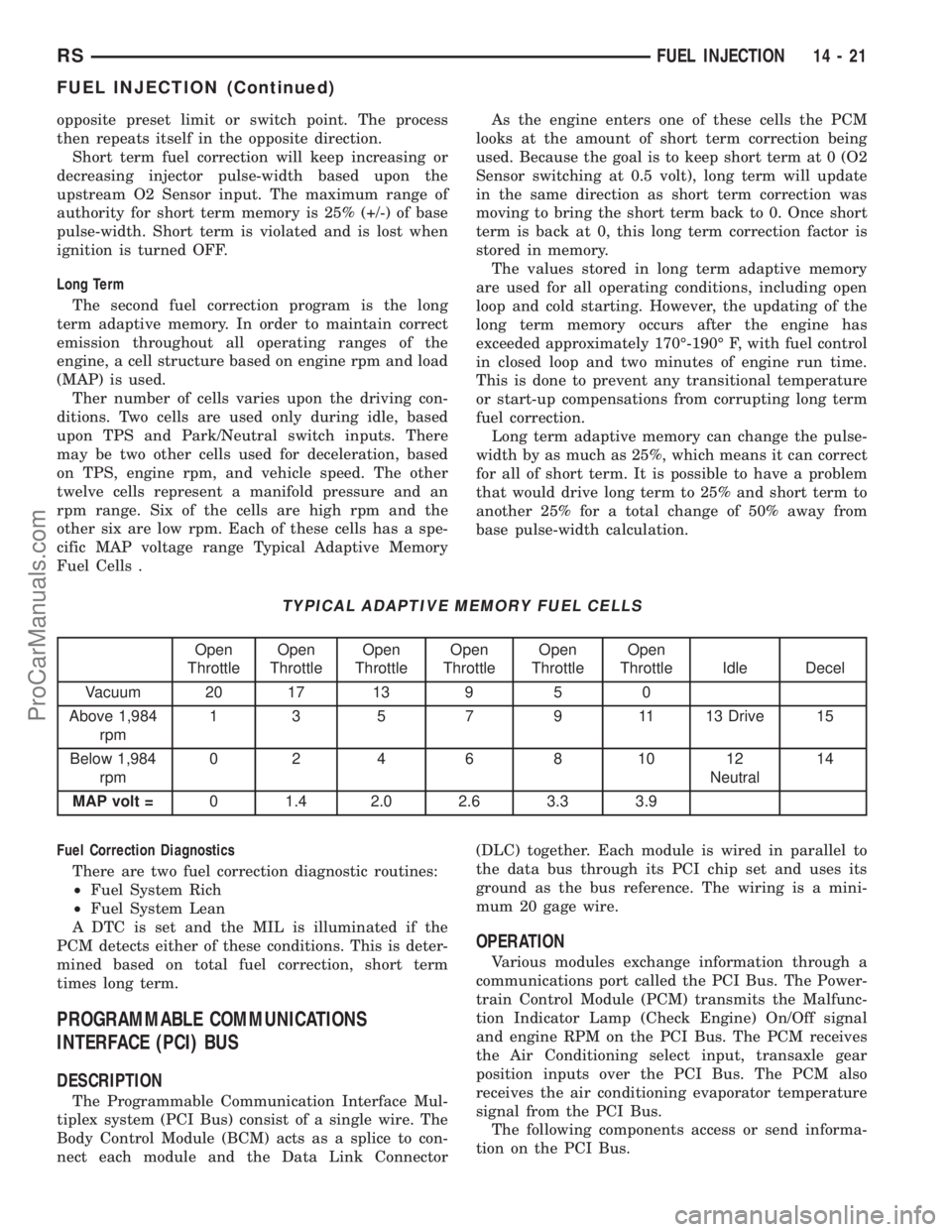
cific MAP voltage range Typical Adaptive Memory
Fuel Cells .As the engine enters one of these cells the PCM
looks at the amount of short term correction being
used. Because the goal is to keep short term at 0 (O2
Sensor switching at 0.5 volt), long term will update
in the same direction as short term correction was
moving to bring the short term back to 0. Once short
term is back at 0, this long term correction factor is
stored in memory.
The values stored in long term adaptive memory
are used for all operating conditions, including open
loop and cold starting. However, the updating of the
long term memory occurs after the engine has
exceeded approximately 170É-190É F, with fuel control
in closed loop and two minutes of engine run time.
This is done to prevent any transitional temperature
or start-up compensations from corrupting long term
fuel correction.
Long term adaptive memory can change the pulse-
width by as much as 25%, which means it can correct
for all of short term. It is possible to have a problem
that would drive long term to 25% and short term to
another 25% for a total change of 50% away from
base pulse-width calculation.
TYPICAL ADAPTIVE MEMORY FUEL CELLS
Open
ThrottleOpen
ThrottleOpen
ThrottleOpen
ThrottleOpen
ThrottleOpen
Throttle Idle Decel
Vacuum 20 17 13 9 5 0
Above 1,984
rpm1 3 5 7 9 11 13 Drive 15
Below 1,984
rpm02 4 6 8 1012
Neutral14
MAP volt =0 1.4 2.0 2.6 3.3 3.9
Fuel Correction Diagnostics
There are two fuel correction diagnostic routines:
²Fuel System Rich
²Fuel System Lean
A DTC is set and the MIL is illuminated if the
PCM detects either of these conditions. This is deter-
mined based on total fuel correction, short term
times long term.
PROGRAMMABLE COMMUNICATIONS
INTERFACE (PCI) BUS
DESCRIPTION
The Programmable Communication Interface Mul-
tiplex system (PCI Bus) consist of a single wire. The
Body Control Module (BCM) acts as a splice to con-
nect each module and the Data Link Connector(DLC) together. Each module is wired in parallel to
the data bus through its PCI chip set and uses its
ground as the bus reference. The wiring is a mini-
mum 20 gage wire.
OPERATION
Various modules exchange information through a
communications port called the PCI Bus. The Power-
train Control Module (PCM) transmits the Malfunc-
tion Indicator Lamp (Check Engine) On/Off signal
and engine RPM on the PCI Bus. The PCM receives
the Air Conditioning select input, transaxle gear
position inputs over the PCI Bus. The PCM also
receives the air conditioning evaporator temperature
signal from the PCI Bus.
The following components access or send informa-
tion on the PCI Bus.
RSFUEL INJECTION14-21
FUEL INJECTION (Continued)
ProCarManuals.com
Page 2112 of 2177
EMISSIONS CONTROL
TABLE OF CONTENTS
page page
EMISSIONS CONTROL
DESCRIPTION
DESCRIPTION - VEHICLE EMISSION
CONTROL INFORMATION LABEL..........1
DESCRIPTION - TRIP DEFINITION.........1
DESCRIPTION - MONITORED COMPONENT . 1
OPERATION - NON-MONITORED CIRCUITS . . 5
DESCRIPTION - MONITORED SYSTEMS....6DESCRIPTION - HIGH AND LOW LIMITS....8
OPERATION
OPERATION - SYSTEM..................9
DRB IIITSTATE DISPLAY TEST MODE......9
EVAPORATIVE EMISSIONS................10
EXHAUST GAS RECIRCULATION...........21
ON-BOARD DIAGNOSTICS................24
EMISSIONS CONTROL
DESCRIPTION
DESCRIPTION - VEHICLE EMISSION CONTROL
INFORMATION LABEL
All models have a Vehicle Emission Control Infor-
mation (VECI) Label. Chrysler permanently attaches
the label in the engine compartment. It cannot be
removed without defacing information and destroying
the label.
The label contains the vehicle's emission specifica-
tions and vacuum hose routings. All hoses must be
connected and routed according to the label.
DESCRIPTION - TRIP DEFINITION
A ªTripº means vehicle operation (following an
engine-off period) of duration and driving mode such
that all components and systems are monitored at
least once by the diagnostic system. The monitors
must successfully pass before the PCM can verify
that a previously malfunctioning component is meet-
ing the normal operating conditions of that compo-
nent. For misfire or fuel system malfunction, the
MIL may be extinguished if the fault does not recur
when monitored during three subsequent sequential
driving cycles in which conditions are similar to
those under which the malfunction was first deter-
mined.
Anytime the MIL is illuminated, a DTC is stored.
The DTC can self erase only after the MIL has been
extinguished. Once the MIL is extinguished, the
PCM must pass the diagnostic test for the most
recent DTC for 40 warm-up cycles (80 warm-up
cycles for the Fuel System Monitor and the Misfire
Monitor). A warm-up cycle can best be described by
the following:
²The engine must be running²A rise of 40ÉF in engine temperature must occur
from the time when the engine was started
²Engine coolant temperature must crossover
160ÉF
²A ªdriving cycleº that consists of engine start up
and engine shut off.
Once the above conditions occur, the PCM is con-
sidered to have passed a warm-up cycle. Due to the
conditions required to extinguish the MIL and erase
the DTC, it is most important that after a repair has
been made, all DTC's be erased and the repair veri-
fied by running 1±good trip.
DESCRIPTION - MONITORED COMPONENT
There are several components that will affect vehi-
cle emissions if they malfunction. If one of these com-
ponents malfunctions the Malfunction Indicator
Lamp (Check Engine) will illuminate.
Some of the component monitors are checking for
proper operation of the part. Electrically operated
components now have input (rationality) and output
(functionality) checks. Previously, a component like
the Throttle Position sensor (TPS) was checked by
the PCM for an open or shorted circuit. If one of
these conditions occurred, a DTC was set. Now there
is a check to ensure that the component is working.
This is done by watching for a TPS indication of a
greater or lesser throttle opening than MAP and
engine rpm indicate. In the case of the TPS, if engine
vacuum is low and engine rpm is 1600 or greater and
the TPS indicates a small throttle opening, a DTC
will be set.
Any component that has an associated limp in will
set a fault after 1 trip with the malfunction present.
Refer to the Diagnostic Trouble Codes Description
Charts (Refer to 8 - ELECTRICAL/ELECTRONIC
CONTROL MODULES/POWERTRAIN CONTROL
MODULE - DESCRIPTION) and the appropriate
Powertrain Diagnostic Procedure Manual for diag-
nostic procedures.
RSEMISSIONS CONTROL25-1
ProCarManuals.com
Page 2117 of 2177
FUEL INJECTOR MECHANICAL MALFUNCTIONS
The PCM cannot determine if a fuel injector is
clogged, the needle is sticking or if the wrong injector
is installed. However, these could result in a rich or
lean condition causing the PCM to store a diagnostic
trouble code for either misfire, an oxygen sensor, or
the fuel system.
EXCESSIVE OIL CONSUMPTION
Although the PCM monitors engine exhaust oxygen
content when the system is in closed loop, it cannot
determine excessive oil consumption.
THROTTLE BODY AIR FLOW
The PCM cannot detect a clogged or restricted air
cleaner inlet or filter element.
VACUUM ASSIST
The PCM cannot detect leaks or restrictions in the
vacuum circuits of vacuum assisted engine control
system devices. However, these could cause the PCM
to store a MAP sensor diagnostic trouble code and
cause a high idle condition.
PCM SYSTEM GROUND
The PCM cannot determine a poor system ground.
However, one or more diagnostic trouble codes may
be generated as a result of this condition. The mod-
ule should be mounted to the body at all times,
including when diagnostics are performed.
PCM CONNECTOR ENGAGEMENT
The PCM may not be able to determine spread or
damaged connector pins. However, it might store
diagnostic trouble codes as a result of spread connec-
tor pins.
DESCRIPTION - MONITORED SYSTEMS
There are new electronic circuit monitors that
check fuel, emission, engine and ignition perfor-
mance. These monitors use information from various
sensor circuits to indicate the overall operation of the
fuel, engine, ignition and emission systems and thus
the emissions performance of the vehicle.
The fuel, engine, ignition and emission systems
monitors do not indicate a specific component prob-
lem. They do indicate that there is an implied prob-
lem within one of the systems and that a specific
problem must be diagnosed.
If any of these monitors detect a problem affecting
vehicle emissions, the Malfunction Indicator (Check
Engine) Lamp will be illuminated. These monitors
generate Diagnostic Trouble Codes that can be dis-
played with the a DRBIIItscan tool.
The following is a list of the system monitors:
²EGR Monitor (if equipped)²Misfire Monitor
²Fuel System Monitor
²Oxygen Sensor Monitor
²Oxygen Sensor Heater Monitor
²Catalyst Monitor
²Evaporative System Leak Detection Monitor (if
equipped)
Following is a description of each system monitor,
and its DTC.
Refer to the appropriate Powertrain Diagnos-
tics Procedures manual for diagnostic proce-
dures.
OXYGEN SENSOR (O2S) MONITOR
Effective control of exhaust emissions is achieved
by an oxygen feedback system. The most important
element of the feedback system is the O2S. The O2S
is located in the exhaust path. Once it reaches oper-
ating temperatures of 300É to 350ÉC (572É to 662ÉF),
the sensor generates a voltage that is inversely pro-
portional to the amount of oxygen in the exhaust.
The information obtained by the sensor is used to
calculate the fuel injector pulse width. The PCM is
programmed to maintain the optimum air/fuel ratio.
At this mixture ratio, the catalyst works best to
remove hydrocarbons (HC), carbon monoxide (CO)
and nitrous oxide (NOx) from the exhaust.
The O2S is also the main sensing element for the
EGR (if equipped), Catalyst and Fuel Monitors.
The O2S may fail in any or all of the following
manners:
²Slow response rate
²Reduced output voltage
²Dynamic shift
²Shorted or open circuits
Response rate is the time required for the sensor to
switch from lean to rich once it is exposed to a richer
than optimum A/F mixture or vice versa. As the sen-
sor starts malfunctioning, it could take longer to
detect the changes in the oxygen content of the
exhaust gas.
The output voltage of the O2S ranges from 0 to 1
volt (voltages are offset by 2.5 volts on NGC vehi-
cles). A good sensor can easily generate any output
voltage in this range as it is exposed to different con-
centrations of oxygen. To detect a shift in the A/F
mixture (lean or rich), the output voltage has to
change beyond a threshold value. A malfunctioning
sensor could have difficulty changing beyond the
threshold value.
OXYGEN SENSOR HEATER MONITOR
If there is an oxygen sensor (O2S) DTC as well as
a O2S heater DTC, the O2S heater fault MUST be
repaired first. After the O2S fault is repaired, verify
that the heater circuit is operating correctly.
25 - 6 EMISSIONS CONTROLRS
EMISSIONS CONTROL (Continued)
ProCarManuals.com
Page 2120 of 2177
OPERATION
OPERATION - SYSTEM
The Powertrain Control Module (PCM) monitors
many different circuits in the fuel injection, ignition,
emission and engine systems. If the PCM senses a
problem with a monitored circuit often enough to
indicate an actual problem, it stores a Diagnostic
Trouble Code (DTC) in the PCM's memory. If the
code applies to a non-emissions related component or
system, and the problem is repaired or ceases to
exist, the PCM cancels the code after 40 warmup
cycles. Diagnostic trouble codes that affect vehicle
emissions illuminate the Malfunction Indicator Lamp
(MIL). Refer to Malfunction Indicator Lamp in this
section.
Certain criteria must be met before the PCM
stores a DTC in memory. The criteria may be a spe-
cific range of engine RPM, engine temperature,
and/or input voltage to the PCM.
The PCM might not store a DTC for a monitored
circuit even though a malfunction has occurred. This
may happen because one of the DTC criteria for the
circuit has not been met.For example, assume the
diagnostic trouble code criteria requires the PCM to
monitor the circuit only when the engine operates
between 750 and 2000 RPM. Suppose the sensor's
output circuit shorts to ground when engine operates
above 2400 RPM (resulting in 0 volt input to the
PCM). Because the condition happens at an engine
speed above the maximum threshold (2000 rpm), the
PCM will not store a DTC.
There are several operating conditions for which
the PCM monitors and sets DTC's. Refer to Moni-
tored Systems, Components, and Non-Monitored Cir-
cuits in this section.
NOTE: Various diagnostic procedures may actually
cause a diagnostic monitor to set a DTC. For
instance, pulling a spark plug wire to perform a
spark test may set the misfire code. When a repair
is completed and verified, use the DRBIIITscan tool
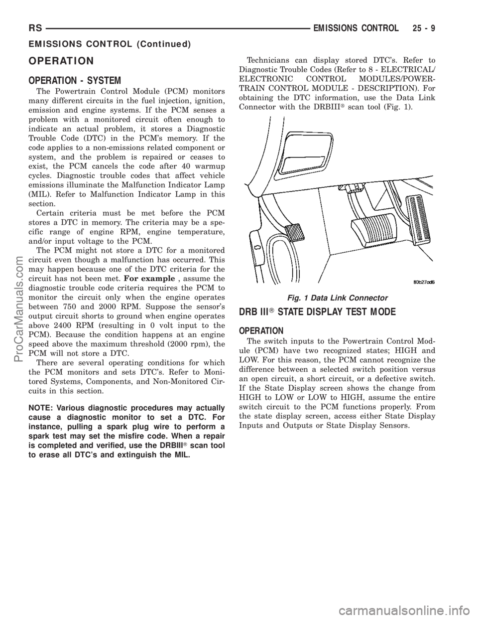
to erase all DTC's and extinguish the MIL.Technicians can display stored DTC's. Refer to
Diagnostic Trouble Codes (Refer to 8 - ELECTRICAL/
ELECTRONIC CONTROL MODULES/POWER-
TRAIN CONTROL MODULE - DESCRIPTION). For
obtaining the DTC information, use the Data Link
Connector with the DRBIIItscan tool (Fig. 1).
DRB IIITSTATE DISPLAY TEST MODE
OPERATION
The switch inputs to the Powertrain Control Mod-
ule (PCM) have two recognized states; HIGH and
LOW. For this reason, the PCM cannot recognize the
difference between a selected switch position versus
an open circuit, a short circuit, or a defective switch.
If the State Display screen shows the change from
HIGH to LOW or LOW to HIGH, assume the entire
switch circuit to the PCM functions properly. From
the state display screen, access either State Display
Inputs and Outputs or State Display Sensors.
Fig. 1 Data Link Connector
RSEMISSIONS CONTROL25-9
EMISSIONS CONTROL (Continued)
ProCarManuals.com