2003 CHRYSLER VOYAGER door switch
[x] Cancel search: door switchPage 1124 of 2177
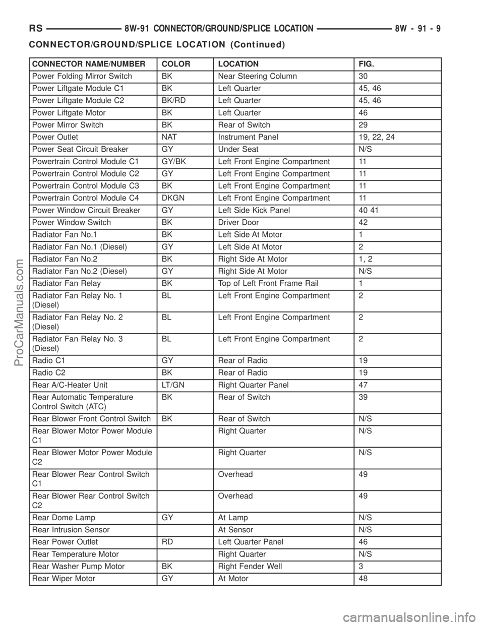
CONNECTOR NAME/NUMBER COLOR LOCATION FIG.
Power Folding Mirror Switch BK Near Steering Column 30
Power Liftgate Module C1 BK Left Quarter 45, 46
Power Liftgate Module C2 BK/RD Left Quarter 45, 46
Power Liftgate Motor BK Left Quarter 46
Power Mirror Switch BK Rear of Switch 29
Power Outlet NAT Instrument Panel 19, 22, 24
Power Seat Circuit Breaker GY Under Seat N/S
Powertrain Control Module C1 GY/BK Left Front Engine Compartment 11
Powertrain Control Module C2 GY Left Front Engine Compartment 11
Powertrain Control Module C3 BK Left Front Engine Compartment 11
Powertrain Control Module C4 DKGN Left Front Engine Compartment 11
Power Window Circuit Breaker GY Left Side Kick Panel 40 41
Power Window Switch BK Driver Door 42
Radiator Fan No.1 BK Left Side At Motor 1
Radiator Fan No.1 (Diesel) GY Left Side At Motor 2
Radiator Fan No.2 BK Right Side At Motor 1, 2
Radiator Fan No.2 (Diesel) GY Right Side At Motor N/S
Radiator Fan Relay BK Top of Left Front Frame Rail 1
Radiator Fan Relay No. 1
(Diesel)BL Left Front Engine Compartment 2
Radiator Fan Relay No. 2
(Diesel)BL Left Front Engine Compartment 2
Radiator Fan Relay No. 3
(Diesel)BL Left Front Engine Compartment 2
Radio C1 GY Rear of Radio 19
Radio C2 BK Rear of Radio 19
Rear A/C-Heater Unit LT/GN Right Quarter Panel 47
Rear Automatic Temperature
Control Switch (ATC)BK Rear of Switch 39
Rear Blower Front Control Switch BK Rear of Switch N/S
Rear Blower Motor Power Module
C1Right Quarter N/S
Rear Blower Motor Power Module
C2Right Quarter N/S
Rear Blower Rear Control Switch
C1Overhead 49
Rear Blower Rear Control Switch
C2Overhead 49
Rear Dome Lamp GY At Lamp N/S
Rear Intrusion Sensor At Sensor N/S
Rear Power Outlet RD Left Quarter Panel 46
Rear Temperature Motor Right Quarter N/S
Rear Washer Pump Motor BK Right Fender Well 3
Rear Wiper Motor GY At Motor 48
RS8W-91 CONNECTOR/GROUND/SPLICE LOCATION8W-91-9
CONNECTOR/GROUND/SPLICE LOCATION (Continued)
ProCarManuals.com
Page 1125 of 2177
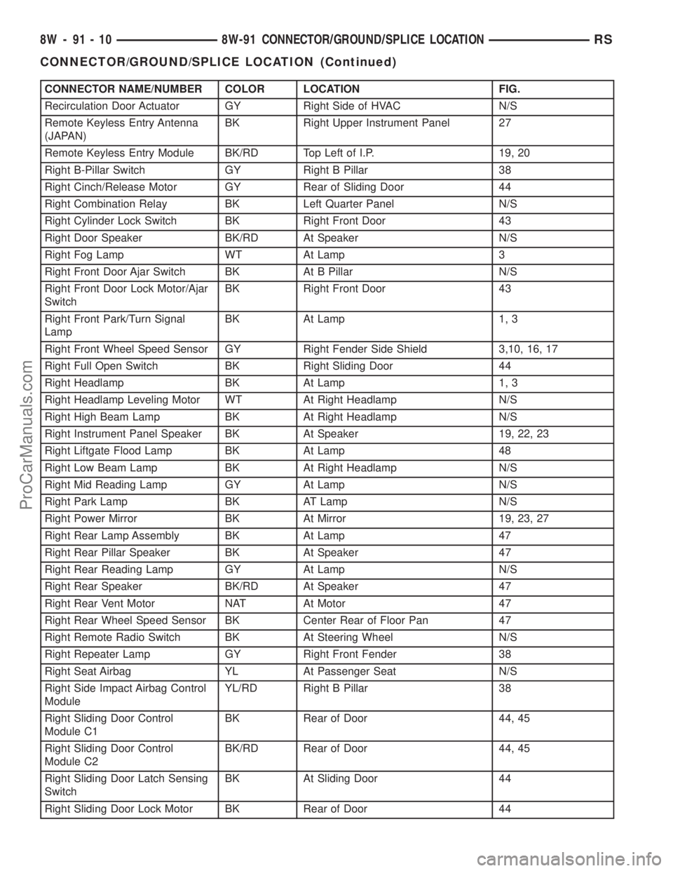
CONNECTOR NAME/NUMBER COLOR LOCATION FIG.
Recirculation Door Actuator GY Right Side of HVAC N/S
Remote Keyless Entry Antenna
(JAPAN)BK Right Upper Instrument Panel 27
Remote Keyless Entry Module BK/RD Top Left of I.P. 19, 20
Right B-Pillar Switch GY Right B Pillar 38
Right Cinch/Release Motor GY Rear of Sliding Door 44
Right Combination Relay BK Left Quarter Panel N/S
Right Cylinder Lock Switch BK Right Front Door 43
Right Door Speaker BK/RD At Speaker N/S
Right Fog Lamp WT At Lamp 3
Right Front Door Ajar Switch BK At B Pillar N/S
Right Front Door Lock Motor/Ajar
SwitchBK Right Front Door 43
Right Front Park/Turn Signal
LampBK At Lamp 1, 3
Right Front Wheel Speed Sensor GY Right Fender Side Shield 3,10, 16, 17
Right Full Open Switch BK Right Sliding Door 44
Right Headlamp BK At Lamp 1, 3
Right Headlamp Leveling Motor WT At Right Headlamp N/S
Right High Beam Lamp BK At Right Headlamp N/S
Right Instrument Panel Speaker BK At Speaker 19, 22, 23
Right Liftgate Flood Lamp BK At Lamp 48
Right Low Beam Lamp BK At Right Headlamp N/S
Right Mid Reading Lamp GY At Lamp N/S
Right Park Lamp BK AT Lamp N/S
Right Power Mirror BK At Mirror 19, 23, 27
Right Rear Lamp Assembly BK At Lamp 47
Right Rear Pillar Speaker BK At Speaker 47
Right Rear Reading Lamp GY At Lamp N/S
Right Rear Speaker BK/RD At Speaker 47
Right Rear Vent Motor NAT At Motor 47
Right Rear Wheel Speed Sensor BK Center Rear of Floor Pan 47
Right Remote Radio Switch BK At Steering Wheel N/S
Right Repeater Lamp GY Right Front Fender 38
Right Seat Airbag YL At Passenger Seat N/S
Right Side Impact Airbag Control
ModuleYL/RD Right B Pillar 38
Right Sliding Door Control
Module C1BK Rear of Door 44, 45
Right Sliding Door Control
Module C2BK/RD Rear of Door 44, 45
Right Sliding Door Latch Sensing
SwitchBK At Sliding Door 44
Right Sliding Door Lock Motor BK Rear of Door 44
8W - 91 - 10 8W-91 CONNECTOR/GROUND/SPLICE LOCATIONRS
CONNECTOR/GROUND/SPLICE LOCATION (Continued)
ProCarManuals.com
Page 1126 of 2177
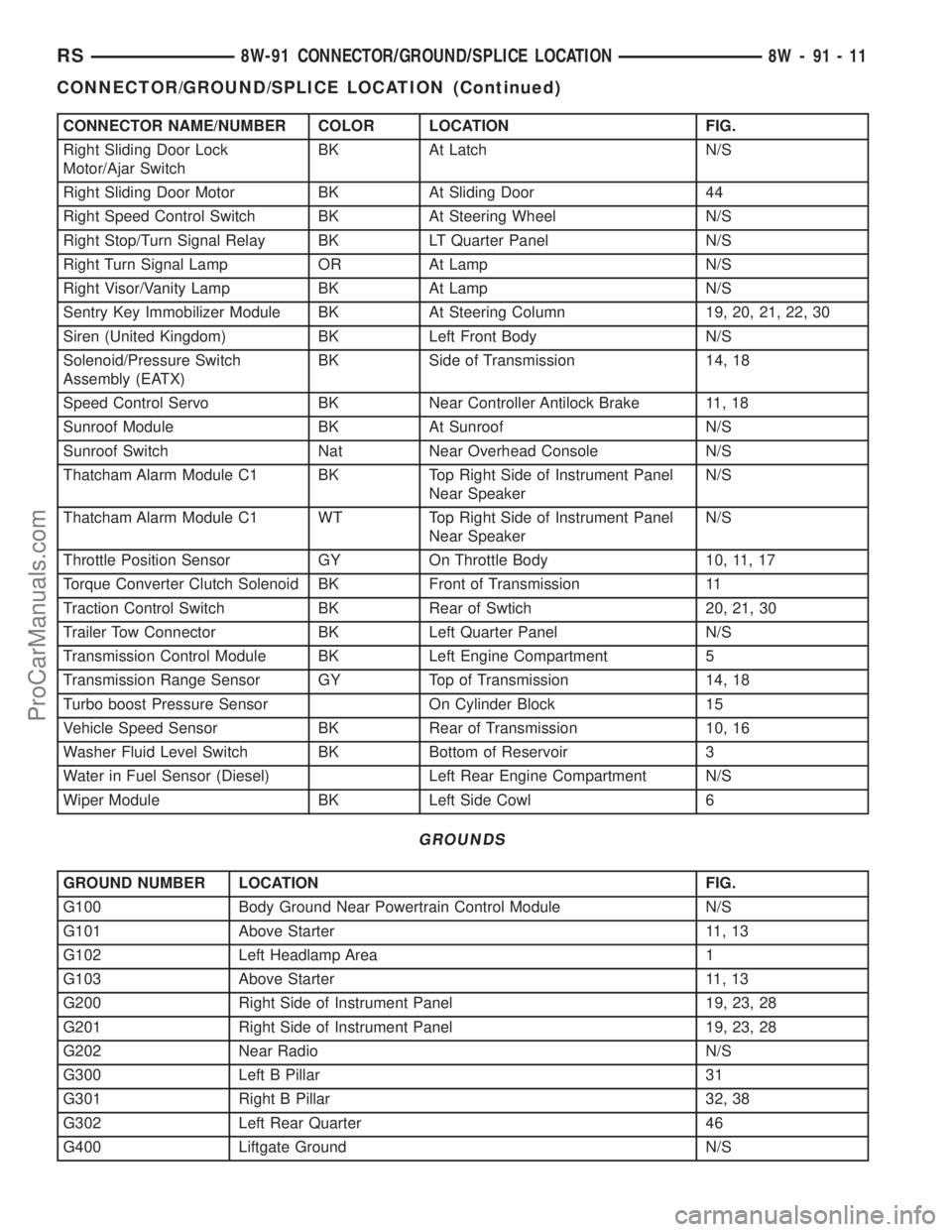
CONNECTOR NAME/NUMBER COLOR LOCATION FIG.
Right Sliding Door Lock
Motor/Ajar SwitchBK At Latch N/S
Right Sliding Door Motor BK At Sliding Door 44
Right Speed Control Switch BK At Steering Wheel N/S
Right Stop/Turn Signal Relay BK LT Quarter Panel N/S
Right Turn Signal Lamp OR At Lamp N/S
Right Visor/Vanity Lamp BK At Lamp N/S
Sentry Key Immobilizer Module BK At Steering Column 19, 20, 21, 22, 30
Siren (United Kingdom) BK Left Front Body N/S
Solenoid/Pressure Switch
Assembly (EATX)BK Side of Transmission 14, 18
Speed Control Servo BK Near Controller Antilock Brake 11, 18
Sunroof Module BK At Sunroof N/S
Sunroof Switch Nat Near Overhead Console N/S
Thatcham Alarm Module C1 BK Top Right Side of Instrument Panel
Near SpeakerN/S
Thatcham Alarm Module C1 WT Top Right Side of Instrument Panel
Near SpeakerN/S
Throttle Position Sensor GY On Throttle Body 10, 11, 17
Torque Converter Clutch Solenoid BK Front of Transmission 11
Traction Control Switch BK Rear of Swtich 20, 21, 30
Trailer Tow Connector BK Left Quarter Panel N/S
Transmission Control Module BK Left Engine Compartment 5
Transmission Range Sensor GY Top of Transmission 14, 18
Turbo boost Pressure Sensor On Cylinder Block 15
Vehicle Speed Sensor BK Rear of Transmission 10, 16
Washer Fluid Level Switch BK Bottom of Reservoir 3
Water in Fuel Sensor (Diesel) Left Rear Engine Compartment N/S
Wiper Module BK Left Side Cowl 6
GROUNDS
GROUND NUMBER LOCATION FIG.
G100 Body Ground Near Powertrain Control Module N/S
G101 Above Starter 11, 13
G102 Left Headlamp Area 1
G103 Above Starter 11, 13
G200 Right Side of Instrument Panel 19, 23, 28
G201 Right Side of Instrument Panel 19, 23, 28
G202 Near Radio N/S
G300 Left B Pillar 31
G301 Right B Pillar 32, 38
G302 Left Rear Quarter 46
G400 Liftgate Ground N/S
RS8W-91 CONNECTOR/GROUND/SPLICE LOCATION8W-91-11
CONNECTOR/GROUND/SPLICE LOCATION (Continued)
ProCarManuals.com
Page 1130 of 2177
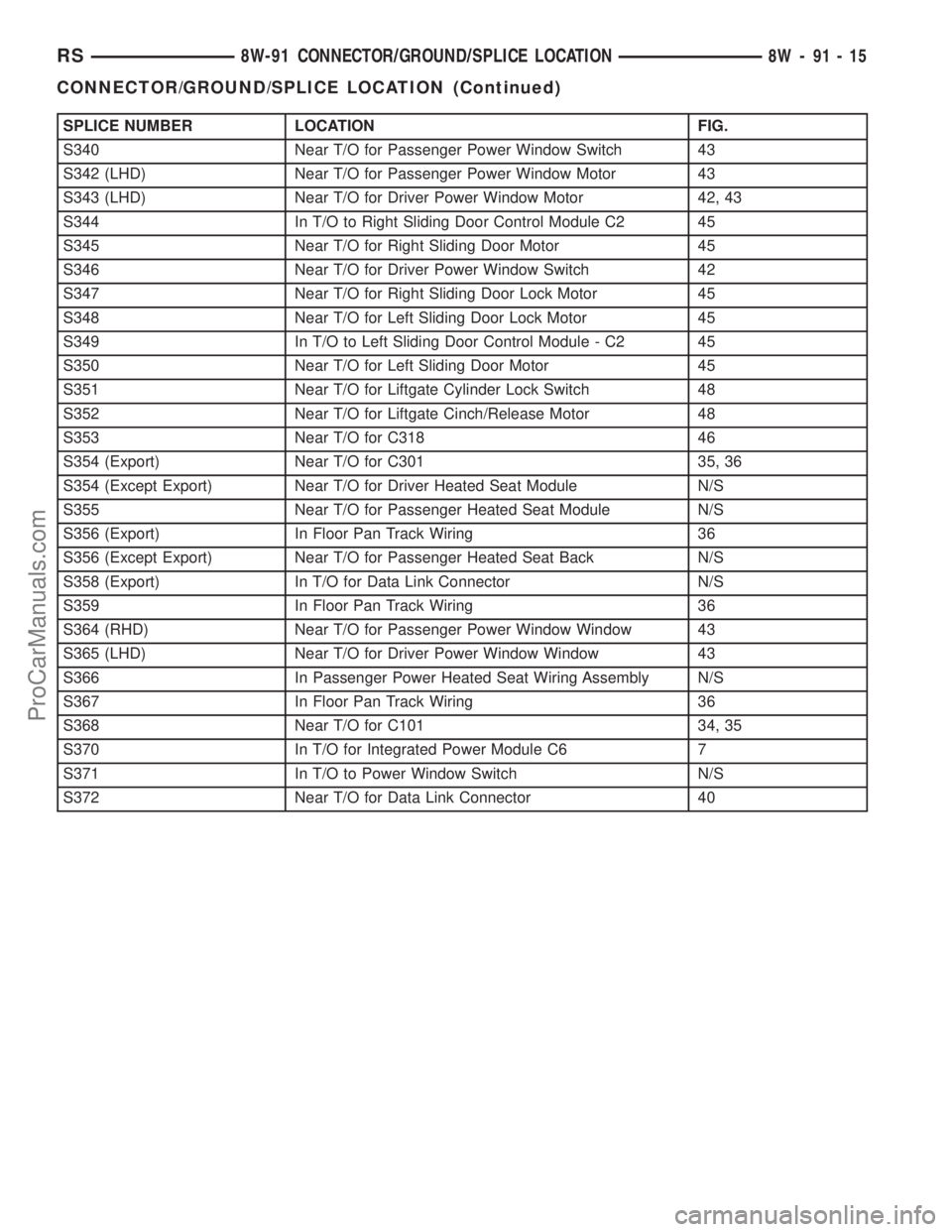
SPLICE NUMBER LOCATION FIG.
S340 Near T/O for Passenger Power Window Switch 43
S342 (LHD) Near T/O for Passenger Power Window Motor 43
S343 (LHD) Near T/O for Driver Power Window Motor 42, 43
S344 In T/O to Right Sliding Door Control Module C2 45
S345 Near T/O for Right Sliding Door Motor 45
S346 Near T/O for Driver Power Window Switch 42
S347 Near T/O for Right Sliding Door Lock Motor 45
S348 Near T/O for Left Sliding Door Lock Motor 45
S349 In T/O to Left Sliding Door Control Module - C2 45
S350 Near T/O for Left Sliding Door Motor 45
S351 Near T/O for Liftgate Cylinder Lock Switch 48
S352 Near T/O for Liftgate Cinch/Release Motor 48
S353 Near T/O for C318 46
S354 (Export) Near T/O for C301 35, 36
S354 (Except Export) Near T/O for Driver Heated Seat Module N/S
S355 Near T/O for Passenger Heated Seat Module N/S
S356 (Export) In Floor Pan Track Wiring 36
S356 (Except Export) Near T/O for Passenger Heated Seat Back N/S
S358 (Export) In T/O for Data Link Connector N/S
S359 In Floor Pan Track Wiring 36
S364 (RHD) Near T/O for Passenger Power Window Window 43
S365 (LHD) Near T/O for Driver Power Window Window 43
S366 In Passenger Power Heated Seat Wiring Assembly N/S
S367 In Floor Pan Track Wiring 36
S368 Near T/O for C101 34, 35
S370 In T/O for Integrated Power Module C6 7
S371 In T/O to Power Window Switch N/S
S372 Near T/O for Data Link Connector 40
RS8W-91 CONNECTOR/GROUND/SPLICE LOCATION8W-91-15
CONNECTOR/GROUND/SPLICE LOCATION (Continued)
ProCarManuals.com
Page 1175 of 2177

SPECIAL TOOLS
POWER DISTRIBUTION SYSTEMS
ACCESSORY RELAY
DESCRIPTION
The accessory relay is an electromechanical device
that switches fused battery current to the accessory
powered vehicle circuits when the ignition switch is
turned to the Accessory or On positions. The delay
feature will maintain power to the accessories for 45
seconds after the ignition is shut off or until a door is
opened. This allows sufficient time to close windows
and park the windshield wipers. The accessory relay
is located in the Integrated Power Module (IPM) in
the engine compartment.
The accessory relay is a International Standards
Organization (ISO) relay. Relays conforming to the
ISO specifications have common physical dimensions,
current capacities, terminal patterns, and terminal
functions.
The accessory relay cannot be repaired or adjusted
and, if faulty or damaged, it must be replaced.
OPERATION
The ISO relay consists of an electromagnetic coil, a
resistor or diode, and three (two fixed and one mov-
able) electrical contacts. The movable (common feed)
relay contact is held against one of the fixed contacts
(normally closed) by spring pressure. When the elec-
tromagnetic coil is energized, it draws the movable
contact away from the normally closed fixed contact,
and holds it against the other (normally open) fixed
contact.
When the electromagnetic coil is de-energized,
spring pressure returns the movable contact to the
normally closed position. The resistor or diode is con-
nected in parallel with the electromagnetic coil in therelay, and helps to dissipate voltage spikes that are
produced when the coil is de-energized.
DIAGNOSIS AND TESTING
DIAGNOSIS & TESTING - ACCESSORY RELAY
The accessory relay (Fig. 1) is located in the Inte-
grated Power Module (IPM), in the engine compart-
ment. For complete circuit diagrams, refer toWiring
Diagrams.
(1) Remove the accessory relay from the IPM.
Refer toAccessory Relayin the Removal and
Installation section of this group for the procedure.
(2) A relay in the de-energized position should
have continuity between terminals 87A and 30, and
no continuity between terminals 87 and 30. If OK, go
to Step 3. If not OK, replace the faulty relay.
(3) Resistance between terminals 85 and 86 (elec-
tromagnet) should be 75 5 ohms. If OK, go to Step
4. If not OK, replace the faulty relay.
(4) Connect a battery to terminals 85 and 86.
There should now be continuity between terminals
30 and 87, and no continuity between terminals 87A
and 30. If OK, perform the Relay Circuit Test that
follows. If not OK, replace the faulty relay.
DIAGNOSIS & TESTING - RELAY CIRCUIT TEST
(1) The relay common feed terminal cavity (30) of
the IPM is connected to battery voltage and should
be hot at all times. Check for battery voltage at the
fused B(+) circuit cavity in the IPM receptacle for the
accessory relay. If OK, go to Step 2. If not OK, repair
the fused B(+) circuit to the IPM fuse as required.
(2) The relay normally closed terminal (87A) is
connected to terminal 30 in the de-energized position,
but is not used for this application. Go to Step 3.
(3) The relay normally open terminal (87) is con-
nected to the common feed terminal (30) in the ener-
gized position. This terminal supplies battery voltage
Terminal Pick Kit 6680
Fig. 1 Accessory Relay
8W - 97 - 2 8W-97 POWER DISTRIBUTION SYSTEMRS
POWER DISTRIBUTION SYSTEM (Continued)
ProCarManuals.com
Page 1752 of 2177
INSTALLATION
NOTE: The screws attaching the door latch to the
door end frame have nylon patches on the threads.
All screws must be replaced when the latch has
been removed.
(1) Insert inside handle latch link to door latch
and engage clip (Fig. 8).
(2) Place door latch in position on door end frame.
(3) Install screws attaching door latch to door end
frame. Tighten screws to 10 N´m (90 in. lbs.) torque
(Fig. 9).
(4) Insert other linkages to door latch and engage
clips.
(5) Connect wire connector into power door lock
motor, if equipped.
(6) Insert a hex wrench through the elongated hole
located in the door shut face above the latch.
(7) Loosen allen head screw.
(8) Pull outward on the outside door handle and
release.
(9) Tighten allen head screw.
(10) Verify door latch and power door lock opera-
tion.
(11) Install watershield and front door trim panel.
LATCH STRIKER
REMOVAL
(1) Mark outline of door striker on B-pillar to aid
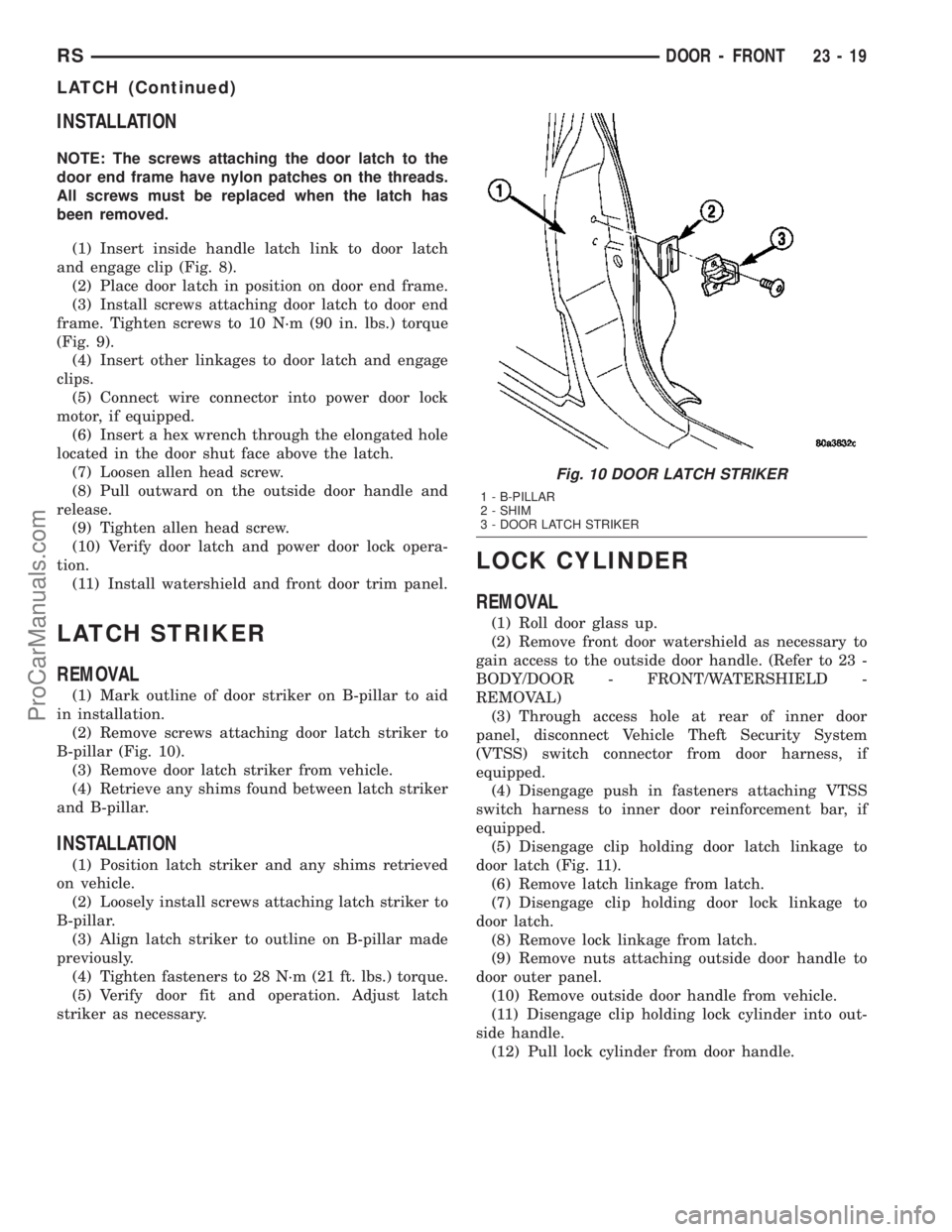
in installation.
(2) Remove screws attaching door latch striker to
B-pillar (Fig. 10).
(3) Remove door latch striker from vehicle.
(4) Retrieve any shims found between latch striker
and B-pillar.
INSTALLATION
(1) Position latch striker and any shims retrieved
on vehicle.
(2) Loosely install screws attaching latch striker to
B-pillar.
(3) Align latch striker to outline on B-pillar made
previously.
(4) Tighten fasteners to 28 N´m (21 ft. lbs.) torque.
(5) Verify door fit and operation. Adjust latch
striker as necessary.
LOCK CYLINDER
REMOVAL
(1) Roll door glass up.
(2) Remove front door watershield as necessary to
gain access to the outside door handle. (Refer to 23 -
BODY/DOOR - FRONT/WATERSHIELD -
REMOVAL)
(3) Through access hole at rear of inner door
panel, disconnect Vehicle Theft Security System
(VTSS) switch connector from door harness, if
equipped.
(4) Disengage push in fasteners attaching VTSS
switch harness to inner door reinforcement bar, if
equipped.
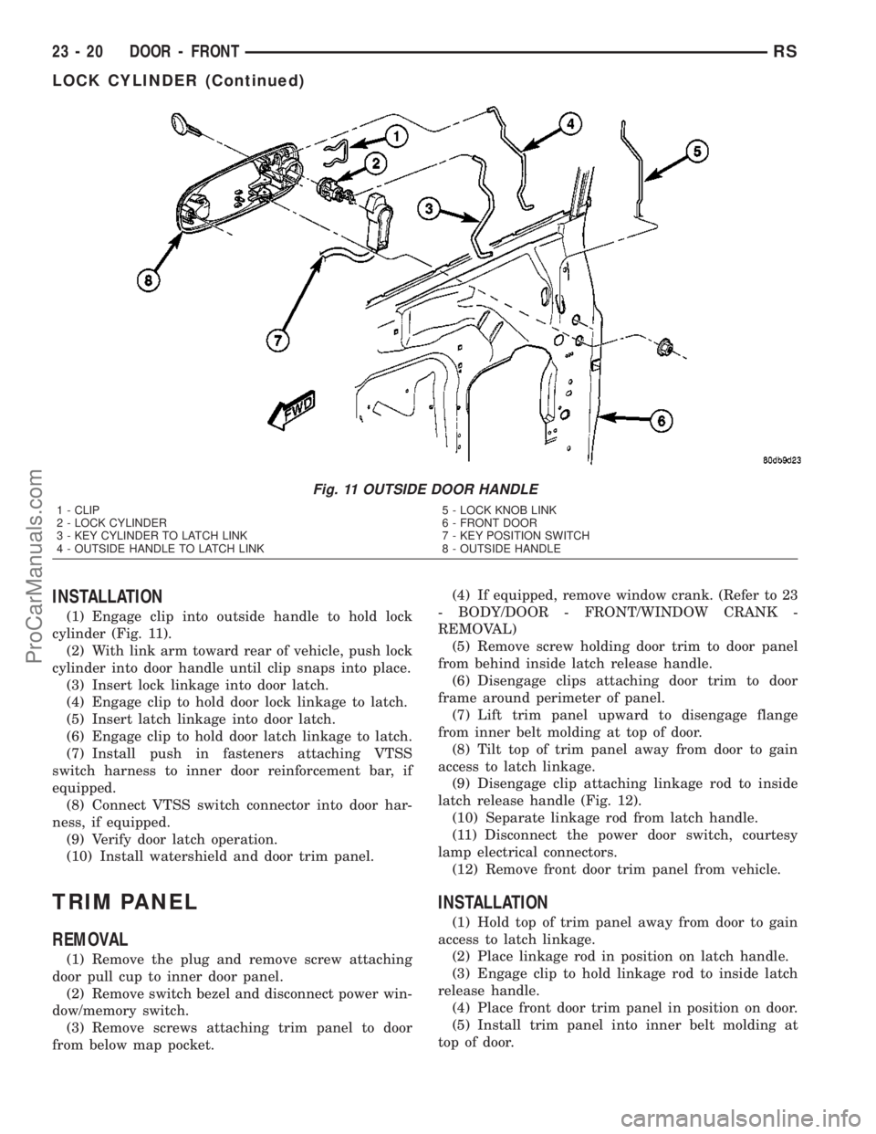
(5) Disengage clip holding door latch linkage to
door latch (Fig. 11).
(6) Remove latch linkage from latch.
(7) Disengage clip holding door lock linkage to
door latch.
(8) Remove lock linkage from latch.
(9) Remove nuts attaching outside door handle to
door outer panel.
(10) Remove outside door handle from vehicle.
(11) Disengage clip holding lock cylinder into out-
side handle.
(12) Pull lock cylinder from door handle.
Fig. 10 DOOR LATCH STRIKER
1 - B-PILLAR
2 - SHIM
3 - DOOR LATCH STRIKER
RSDOOR - FRONT23-19
LATCH (Continued)
ProCarManuals.com
Page 1753 of 2177
INSTALLATION
(1) Engage clip into outside handle to hold lock
cylinder (Fig. 11).
(2) With link arm toward rear of vehicle, push lock
cylinder into door handle until clip snaps into place.
(3) Insert lock linkage into door latch.
(4) Engage clip to hold door lock linkage to latch.
(5) Insert latch linkage into door latch.
(6) Engage clip to hold door latch linkage to latch.
(7) Install push in fasteners attaching VTSS
switch harness to inner door reinforcement bar, if
equipped.
(8) Connect VTSS switch connector into door har-
ness, if equipped.
(9) Verify door latch operation.
(10) Install watershield and door trim panel.
TRIM PANEL
REMOVAL
(1) Remove the plug and remove screw attaching
door pull cup to inner door panel.
(2) Remove switch bezel and disconnect power win-
dow/memory switch.
(3) Remove screws attaching trim panel to door
from below map pocket.(4) If equipped, remove window crank. (Refer to 23
- BODY/DOOR - FRONT/WINDOW CRANK -
REMOVAL)
(5) Remove screw holding door trim to door panel
from behind inside latch release handle.
(6) Disengage clips attaching door trim to door
frame around perimeter of panel.
(7) Lift trim panel upward to disengage flange
from inner belt molding at top of door.
(8) Tilt top of trim panel away from door to gain
access to latch linkage.
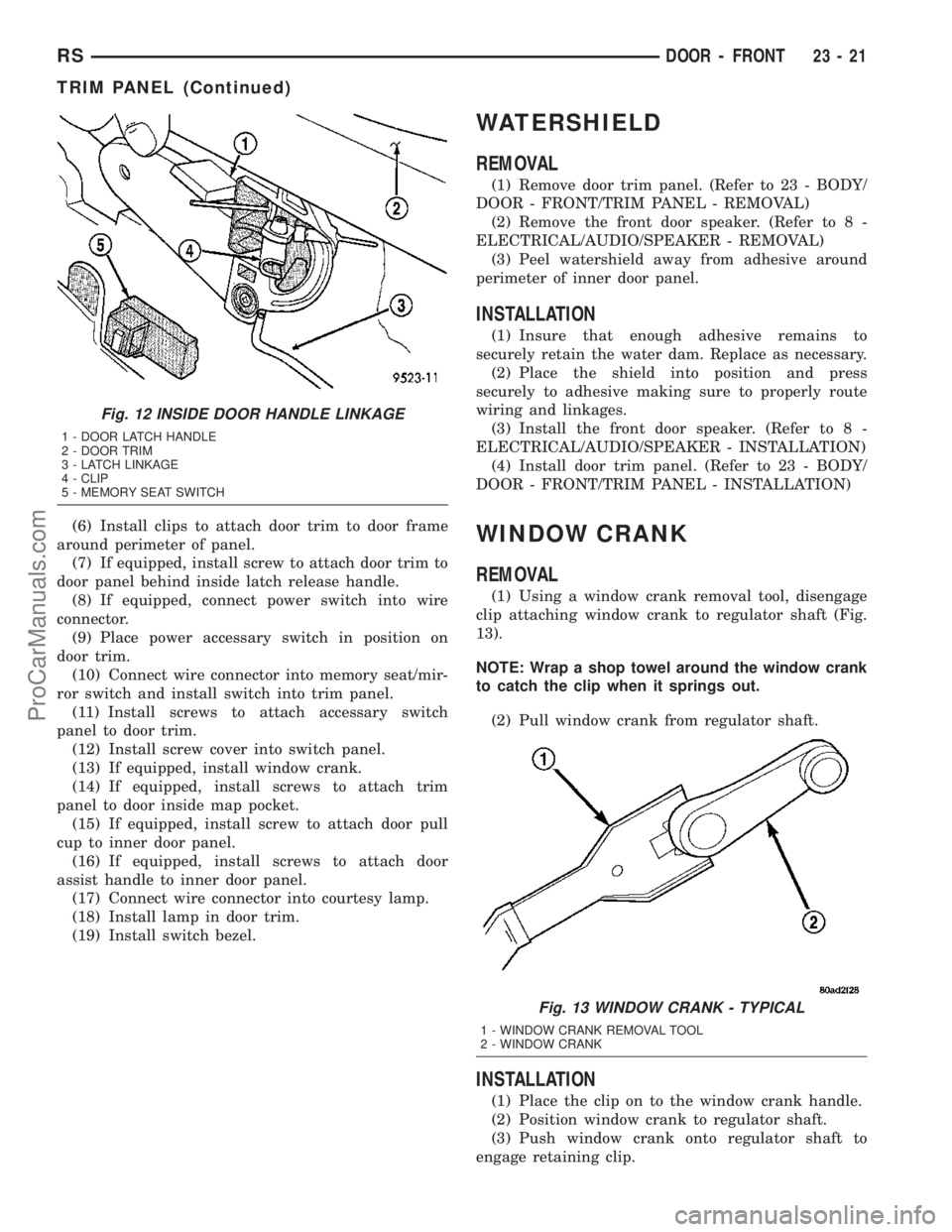
(9) Disengage clip attaching linkage rod to inside
latch release handle (Fig. 12).
(10) Separate linkage rod from latch handle.
(11) Disconnect the power door switch, courtesy
lamp electrical connectors.
(12) Remove front door trim panel from vehicle.
INSTALLATION
(1) Hold top of trim panel away from door to gain
access to latch linkage.
(2) Place linkage rod in position on latch handle.
(3) Engage clip to hold linkage rod to inside latch
release handle.
(4) Place front door trim panel in position on door.
(5) Install trim panel into inner belt molding at
top of door.
Fig. 11 OUTSIDE DOOR HANDLE
1 - CLIP
2 - LOCK CYLINDER
3 - KEY CYLINDER TO LATCH LINK
4 - OUTSIDE HANDLE TO LATCH LINK5 - LOCK KNOB LINK
6 - FRONT DOOR
7 - KEY POSITION SWITCH
8 - OUTSIDE HANDLE
23 - 20 DOOR - FRONTRS
LOCK CYLINDER (Continued)
ProCarManuals.com
Page 1754 of 2177
(6) Install clips to attach door trim to door frame
around perimeter of panel.
(7) If equipped, install screw to attach door trim to
door panel behind inside latch release handle.
(8) If equipped, connect power switch into wire
connector.
(9) Place power accessary switch in position on
door trim.
(10) Connect wire connector into memory seat/mir-
ror switch and install switch into trim panel.
(11) Install screws to attach accessary switch
panel to door trim.
(12) Install screw cover into switch panel.
(13) If equipped, install window crank.
(14) If equipped, install screws to attach trim
panel to door inside map pocket.
(15) If equipped, install screw to attach door pull
cup to inner door panel.
(16) If equipped, install screws to attach door
assist handle to inner door panel.
(17) Connect wire connector into courtesy lamp.
(18) Install lamp in door trim.
(19) Install switch bezel.
WATERSHIELD
REMOVAL
(1) Remove door trim panel. (Refer to 23 - BODY/
DOOR - FRONT/TRIM PANEL - REMOVAL)
(2) Remove the front door speaker. (Refer to 8 -
ELECTRICAL/AUDIO/SPEAKER - REMOVAL)
(3) Peel watershield away from adhesive around
perimeter of inner door panel.
INSTALLATION
(1) Insure that enough adhesive remains to
securely retain the water dam. Replace as necessary.
(2) Place the shield into position and press
securely to adhesive making sure to properly route
wiring and linkages.
(3) Install the front door speaker. (Refer to 8 -
ELECTRICAL/AUDIO/SPEAKER - INSTALLATION)
(4) Install door trim panel. (Refer to 23 - BODY/
DOOR - FRONT/TRIM PANEL - INSTALLATION)
WINDOW CRANK
REMOVAL
(1) Using a window crank removal tool, disengage
clip attaching window crank to regulator shaft (Fig.
13).
NOTE: Wrap a shop towel around the window crank
to catch the clip when it springs out.
(2) Pull window crank from regulator shaft.
INSTALLATION
(1) Place the clip on to the window crank handle.
(2) Position window crank to regulator shaft.
(3) Push window crank onto regulator shaft to
engage retaining clip.
Fig. 12 INSIDE DOOR HANDLE LINKAGE
1 - DOOR LATCH HANDLE
2 - DOOR TRIM
3 - LATCH LINKAGE
4 - CLIP
5 - MEMORY SEAT SWITCH
Fig. 13 WINDOW CRANK - TYPICAL
1 - WINDOW CRANK REMOVAL TOOL
2 - WINDOW CRANK
RSDOOR - FRONT23-21
TRIM PANEL (Continued)
ProCarManuals.com