2003 CHRYSLER CARAVAN fuel pump
[x] Cancel search: fuel pumpPage 2109 of 2177
(8) Tighten the two M8 fasteners at the rail to 23
Nm (17 ft. lbs.). Taking care so that the exhaust tube
bracket tab is on the top of the heater bracket.
(9) Install the wiring harness(Refer to 24 - HEAT-
ING & AIR CONDITIONING/CABIN HEATER/
HEATER UNIT - INSTALLATION).
(10) Tighten the hose and tube assembly to the
toe-board cross member at two locations.
(11) Install the second hose to the underbody hose
and tube assembly.
(12) Connect the rubber fuel hose between the
body tube assembly and the fuel pump nipple at the
body tube joint. Close the fuel fill cap.
(13) Remove the heater unit support device from
under the vehicle.
(14) Lower vehicle from lift.
(15) Refill cooling system(Refer to 7 - COOLING -
STANDARD PROCEDURE).
(16) Verify function of the cabin heater.
SUPPLEMENTAL DIESEL
HEATER WIRING
REMOVAL
(1) Elevate vehicle on a lift taking note of the
exhaust tube flexible section.
(2) Unplug connector from vehicle wiring harness
to cabin heater harness.
(3) Unplug connector from cabin heater harness to
dosing pump connector.
(4) Unplug two connectors from cabin heater har-
ness to cabin heater controller connectors.
(5) Remove two wiring harness connectors from
underbody.
(6) Remove two wiring harness connectors from
cabin heater shield.
(7) Carefully route the cabin heater harness to the
left side between the cabin heater unit and the cabin
heater shield.
INSTALLATION
(1) Carefully route the cabin heater harness from
the left side of the cabin heater between the cabin
heater unit and the cabin heater shield.
(2) Install the two wiring harness retaining con-
nectors to the cabin heater shield.
(3) Route the wiring harness along the underside
of the vehicle and install the two wiring harness
retaining connectors.
(4) Plug the two connectors from the cabin heater
harness to the cabin heater controller.
(5) Plug the connector to the cabin heater harness
to the dosing pump connector.
(6) Plug the connector from the vehicle wiring har-
ness to the cabin heater harness.(7) Lower the vehicle.
(8) Verify function of the cabin heater.
AIR INTAKE PIPE
REMOVAL
NOTE: Heater air intake tube is part of an assembly
that includes the heater cooling intake and return
pipes. If heater air intake tube requires removal or
replacement the entire assembly will require remov-
al/replacement.
(1) Drain cooling system(Refer to 7 - COOLING -
STANDARD PROCEDURE).
(2) Remove clamps from the heater tubes at the
lower heater port and the lower EGR connector
which are located under the hood.
(3) Remove the retaining clamp at the heater air
intake muffler connection(Refer to 24 - HEATING &
AIR CONDITIONING/CABIN HEATER/INLET
MUFFLER - REMOVAL).
(4) Remove the clamp at the flexible tube to steel
tube connection (Fig. 4).
Fig. 4 FLEXIBLE AIR INTAKE LINE
1 - HEATER UNIT AND SPLASH SHIELD
2 - DOSING PUMP
3 - DOSING PUMP FUEL LINE
4 - FLEXIBLE INTAKE LINE
5 - CLAMP
6 - STEEL INTAKE PIPE
24 - 112 DIESEL SUPPLEMENTAL HEATER - DCHA - EXPORTRS
HEATER UNIT (Continued)
ProCarManuals.com
Page 2113 of 2177
The following is a list of the monitored compo-
nents:
²Comprehensive Components
²Oxygen Sensor Monitor
²Oxygen Sensor Heater Monitor
²Catalyst Monitor
COMPREHENSIVE COMPONENTS
Along with the major monitors, OBD II requires
that the diagnostic system monitor any component
that could affect emissions levels. In many cases,
these components were being tested under OBD I.
The OBD I requirements focused mainly on testing
emissions-related components for electrical opens and
shorts.
However, OBD II also requires that inputs from
powertrain components to the PCM be tested for
rationality, and that outputs to powertrain compo-
nents from the PCM be tested forfunctionality.
Methods for monitoring the various Comprehensive
Component monitoring include:
(1) Circuit Continuity
²Open
²Shorted high
²Shorted to ground
(2) Rationality or Proper Functioning
²Inputs tested for rationality
²Outputs tested for functionality
NOTE: Comprehensive component monitors are
continuous. Therefore, enabling conditions do not
apply.
Input RationalityÐWhile input signals to the
PCM are constantly being monitored for electrical
opens and shorts, they are also tested for rationality.
This means that the input signal is compared against
other inputs and information to see if it makes sense
under the current conditions.
PCM sensor inputs that are checked for rationality
include:
²Manifold Absolute Pressure (MAP) Sensor
²Oxygen Sensor (O2S)
²Engine Coolant Temperature (ECT) Sensor
²Camshaft Position (CMP) Sensor
²Vehicle Speed Sensor
²Crankshaft Position (CKP) Sensor
²Intake/inlet Air Temperature (IAT) Sensor
²Throttle Position (TPS) Sensor
²Ambient Temperature Sensors
²Power Steering Switch
²Oxygen Sensor Heater
²Brake Switch
²Leak Detection Pump Switch or NVLD switch (if
equipped)
²P/N SwitchOutput FunctionalityÐPCM outputs are tested
for functionality in addition to testing for opens and
shorts. When the PCM provides a voltage to an out-
put component, it can verify that the command was
carried out by monitoring specific input signals for
expected changes. For example, when the PCM com-
mands the Idle Air Control (IAC) Motor to a specific
position under certain operating conditions, it expects
to see a specific (target) idle speed (RPM). If it does
not, it stores a DTC.
PCM outputs monitored for functionality include:
²Fuel Injectors
²Ignition Coils
²Idle Air Control
²Purge Solenoid
²EGR Solenoid (if equipped)
²LDP Solenoid or NVLD solenoid (if equipped)
²Radiator Fan Control
²Trans Controls
OXYGEN SENSOR (O2S) MONITOR
DESCRIPTIONÐEffective control of exhaust
emissions is achieved by an oxygen feedback system.
The most important element of the feedback system
is the O2S. The O2S is located in the exhaust path.
Once it reaches operating temperature 300É to 350ÉC
(572É to 662ÉF), the sensor generates a voltage that
is inversely proportional to the amount of oxygen in
the exhaust. When there is a large amount of oxygen
in the exhaust caused by a lean condition, the sensor
produces a low voltage, below 450 mV. When the oxy-
gen content is lower, caused by a rich condition, the
sensor produces a higher voltage, above 450mV (volt-
ages are offset by 2.5 volts on NGC vehicles).
The information obtained by the sensor is used to
calculate the fuel injector pulse width. The PCM is
programmed to maintain the optimum air/fuel ratio.
At this mixture ratio, the catalyst works best to
remove hydrocarbons (HC), carbon monoxide (CO)
and nitrous oxide (NOx) from the exhaust.
The O2S is also the main sensing element for the
EGR (if equipped), Catalyst and Fuel Monitors.
The O2S may fail in any or all of the following
manners:
²Slow response rate (Big Slope)
²Reduced output voltage (Half Cycle)
²Heater Performance
Slow Response Rate (Big Slope)ÐResponse rate
is the time required for the sensor to switch from
lean to rich signal output once it is exposed to a
richer than optimum A/F mixture or vice versa. As
the PCM adjusts the air/fuel ratio, the sensor must
be able to rapidly detect the change. As the sensor
ages, it could take longer to detect the changes in the
oxygen content of the exhaust gas. The rate of
change that an oxygen sensor experiences is called
25 - 2 EMISSIONS CONTROLRS
EMISSIONS CONTROL (Continued)
ProCarManuals.com
Page 2116 of 2177
period the switch ratio reaches a predetermined
value, a counter is incremented by one. The monitor
is enabled to run another test during that trip. When
the test fails 6 times, the counter increments to 3, a
malfunction is entered, and a Freeze Frame is stored,
the code is matured and the MIL is illuminated. If
the first test passes, no further testing is conducted
during that trip.
The MIL is extinguished after three consecutive
good trips. The good trip criteria for the catalyst
monitor is more stringent than the failure criteria. In
order to pass the test and increment one good trip,
the downstream sensor switch rate must be less than
45% of the upstream rate. The failure percentages
are 59% respectively.
Enabling ConditionsÐThe following conditions
must typically be met before the PCM runs the cat-
alyst monitor. Specific times for each parameter may
be different from engine to engine.
²Accumulated drive time
²Enable time
²Ambient air temperature
²Barometric pressure
²Catalyst warm-up counter
²Engine coolant temperature
²Vehicle speed
²MAP
²RPM
²Engine in closed loop
²Fuel level
Pending ConditionsÐ
²Misfire DTC
²Front Oxygen Sensor Response
²Front Oxygen Sensor Heater Monitor
²Front Oxygen Sensor Electrical
²Rear Oxygen Sensor Rationality (middle check)
²Rear Oxygen Sensor Heater Monitor
²Rear Oxygen Sensor Electrical
²Fuel System Monitor
²All TPS faults
²All MAP faults
²All ECT sensor faults
²Purge flow solenoid functionality
²Purge flow solenoid electrical
²All PCM self test faults
²All CMP and CKP sensor faults
²All injector and ignition electrical faults
²Idle Air Control (IAC) motor functionality
²Vehicle Speed Sensor
²Brake switch (auto trans only)
²Intake air temperature
ConflictÐThe catalyst monitor does not run if any
of the following are conditions are present:
²EGR Monitor in progress (if equipped)
²Fuel system rich intrusive test in progress
²EVAP Monitor in progress²Time since start is less than 60 seconds
²Low fuel level-less than 15 %
²Low ambient air temperature
²Ethanol content learn is taking place and the
ethanol used once flag is set
SuspendÐThe Task Manager does not mature a
catalyst fault if any of the following are present:
²Oxygen Sensor Monitor, Priority 1
²Oxygen Sensor Heater, Priority 1
²EGR Monitor, Priority 1 (if equipped)
²EVAP Monitor, Priority 1
²Fuel System Monitor, Priority 2
²Misfire Monitor, Priority 2
OPERATION - NON-MONITORED CIRCUITS
The PCM does not monitor all circuits, systems
and conditions that could have malfunctions causing
driveability problems. However, problems with these
systems may cause the PCM to store diagnostic trou-
ble codes for other systems or components. For exam-
ple, a fuel pressure problem will not register a fault
directly, but could cause a rich/lean condition or mis-
fire. This could cause the PCM to store an oxygen
sensor or misfire diagnostic trouble code.
The major non-monitored circuits are listed below
along with examples of failures modes that do not
directly cause the PCM to set a DTC, but for a sys-
tem that is monitored.
FUEL PRESSURE
The fuel pressure regulator controls fuel system
pressure. The PCM cannot detect a clogged fuel
pump inlet filter, clogged in-line fuel filter, or a
pinched fuel supply or return line. However, these
could result in a rich or lean condition causing the
PCM to store an oxygen sensor, fuel system, or mis-
fire diagnostic trouble code.
SECONDARY IGNITION CIRCUIT
The PCM cannot detect an inoperative ignition coil,
fouled or worn spark plugs, ignition cross firing, or
open spark plug cables. The misfire will however,
increase the oxygen content in the exhaust, deceiving
the PCM in to thinking the fuel system is too lean.
Also see misfire detection.
CYLINDER COMPRESSION
The PCM cannot detect uneven, low, or high engine
cylinder compression. Low compression lowers O2
content in the exhaust. Leading to fuel system, oxy-
gen sensor, or misfire detection fault.
EXHAUST SYSTEM
The PCM cannot detect a plugged, restricted or
leaking exhaust system. It may set a EGR (if
equipped) or Fuel system or O2S fault.
RSEMISSIONS CONTROL25-5
EMISSIONS CONTROL (Continued)
ProCarManuals.com
Page 2119 of 2177
chemical reaction takes place. This means the con-
centration of oxygen will be the same downstream as
upstream. The output voltage of the downstream
O2S copies the voltage of the upstream sensor. The
only difference is a time lag (seen by the PCM)
between the switching of the O2S's.
To monitor the system, the number of lean-to-rich
switches of upstream and downstream O2S's is
counted. The ratio of downstream switches to
upstream switches is used to determine whether the
catalyst is operating properly. An effective catalyst
will have fewer downstream switches than it has
upstream switches i.e., a ratio closer to zero. For a
totally ineffective catalyst, this ratio will be one-to-
one, indicating that no oxidation occurs in the device.
The system must be monitored so that when cata-
lyst efficiency deteriorates and exhaust emissions
increase to over the legal limit, the MIL (Check
Engine lamp) will be illuminated.
NATURAL VACUUM LEAK DETECTION (NVLD) (if equipped)
The Natural Vacuum Leak Detection (NVLD) sys-
tem is the next generation evaporative leak detection
system that will first be used on vehicles equipped
with the Next Generation Controller (NGC). This
new system replaces the leak detection pump as the
method of evaporative system leak detection. This is
to detect a leak equivalent to a 0.0209(0.5 mm) hole.
This system has the capability to detect holes of this
size very dependably.
The basic leak detection theory employed with
NVLD is the9Gas Law9. This is to say that the pres-
sure in a sealed vessel will change if the temperature
of the gas in the vessel changes. The vessel will only
see this effect if it is indeed sealed. Even small leaks
will allow the pressure in the vessel to come to equi-
librium with the ambient pressure. In addition to the
detection of very small leaks, this system has the
capability of detecting medium as well as large evap-
orative system leaks.
The NVLD seals the canister vent during engine off
conditions. If the EVAP system has a leak of less than
the failure threshold, the evaporative system will be
pulled into a vacuum, either due to the cool down
from operating temperature or diurnal ambient tem-
perature cycling. The diurnal effect is considered one
of the primary contributors to the leak determination
by this diagnostic. When the vacuum in the system
exceeds about 19H2O (0.25 KPA), a vacuum switch
closes. The switch closure sends a signal to the NGC.
The NGC, via appropriate logic strategies (described
below), utilizes the switch signal, or lack thereof, to
make a determination of whether a leak is present.
The NVLD device is designed with a normally open
vacuum switch, a normally closed solenoid, and a
seal, which is actuated by both the solenoid and a
diaphragm. The NVLD is located on the atmosphericvent side of the canister. The NVLD assembly may
be mounted on top of the canister outlet, or in-line
between the canister and atmospheric vent filter. The
normally open vacuum switch will close with about 19
H2O (0.25 KPA) vacuum in the evaporative system.
The diaphragm actuates the switch. This is above the
opening point of the fuel inlet check valve in the fill
tube so cap off leaks can be detected. Submerged fill
systems must have recirculation lines that do not
have the in-line normally closed check valve that pro-
tects the system from failed nozzle liquid ingestion,
in order to detect cap off conditions.
The normally closed valve in the NVLD is intended
to maintain the seal on the evaporative system dur-
ing the engine off condition. If vacuum in the evapo-
rative system exceeds 39to 69H2O (0.75 to 1.5 KPA),
the valve will be pulled off the seat, opening the seal.
This will protect the system from excessive vacuum
as well as allowing sufficient purge flow in the event
that the solenoid was to become inoperative.
The solenoid actuates the valve to unseal the can-
ister vent while the engine is running. It also will be
used to close the vent during the medium and large
leak tests and during the purge flow check. This sole-
noid requires initial 1.5 amps of current to pull the
valve open but after 100 ms. will be duty cycled down
to an average of about 150 mA for the remainder of
the drive cycle.
Another feature in the device is a diaphragm that
will open the seal in the NVLD with pressure in the
evaporative system. The device will9blow off9at
about 0.59H2O (0.12 KPA) pressure to permit the
venting of vapors during refueling. An added benefit
to this is that it will also allow the tank to9breathe9
during increasing temperatures, thus limiting the
pressure in the tank to this low level. This is benefi-
cial because the induced vacuum during a subse-
quent declining temperature will achieve the switch
closed (pass threshold) sooner than if the tank had to
decay from a built up pressure.
The device itself has 3 wires: Switch sense, sole-
noid driver and ground. It also includes a resistor to
protect the switch from a short to battery or a short
to ground. The NGC utilizes a high-side driver to
energize and duty-cycle the solenoid.
DESCRIPTION - HIGH AND LOW LIMITS
The PCM compares input signal voltages from each
input device with established high and low limits for
the device. If the input voltage is not within limits
and other criteria are met, the PCM stores a diagnos-
tic trouble code in memory. Other diagnostic trouble
code criteria might include engine RPM limits or
input voltages from other sensors or switches that
must be present before verifying a diagnostic trouble
code condition.
25 - 8 EMISSIONS CONTROLRS
EMISSIONS CONTROL (Continued)
ProCarManuals.com
Page 2121 of 2177
EVAPORATIVE EMISSIONS
TABLE OF CONTENTS
page page
EVAPORATIVE EMISSIONS
OPERATION - EVAPORATION CONTROL
SYSTEM............................10
SPECIFICATIONS
TORQUE............................11
EVAP/PURGE SOLENOID
DESCRIPTION.........................12
OPERATION...........................12
REMOVAL.............................12
INSTALLATION.........................12
FUEL FILLER CAP
DESCRIPTION.........................12
OPERATION...........................12
NATURAL VAC LEAK DETECTION ASSY
REMOVAL.............................13
INSTALLATION.........................13
LEAK DETECTION PUMP
REMOVAL.............................13
INSTALLATION.........................13ORVR
OPERATION...........................14
DIAGNOSIS AND TESTING - VEHICLE DOES
NOT FILL............................16
P C V VA LV E
DESCRIPTION.........................16
OPERATION...........................16
DIAGNOSIS AND TESTING - PCV SYSTEM . . . 17
VAPOR CANISTER
DESCRIPTION.........................18
OPERATION...........................18
REMOVAL
REMOVAL...........................18
REMOVAL - WITH NVLD................19
REMOVAL - REAR EVAP CANISTER.......19
INSTALLATION
INSTALLATION.......................19
INSTALLATION - WITH NVLD............20
INSTALLATION - REAR EVAP CANISTER . . . 20
EVAPORATIVE EMISSIONS
OPERATION - EVAPORATION CONTROL
SYSTEM
The evaporation control system prevents the emis-
sion of fuel tank vapors into the atmosphere. When
fuel evaporates in the fuel tank, the vapors pass
through vent hoses or tubes to an activated carbon
filled evaporative canister. The canister temporarily
holds the vapors. The Powertrain Control Module
(PCM) allows intake manifold vacuum to draw
vapors into the combustion chambers during certain
operating conditions (Fig. 1).All engines use a proportional purge solenoid sys-
tem. The PCM controls vapor flow by operating the
purge solenoid. Refer to Proportional Purge Solenoid
in this section.
NOTE: The evaporative system uses specially man-
ufactured hoses. If they need replacement, only use
fuel resistant hose. Also the hoses must be able to
pass an Ozone compliance test.
NOTE: For more information on Onboard Refueling
Vapor Recovery (ORVR), refer to the Fuel Delivery
section.
25 - 10 EVAPORATIVE EMISSIONSRS
ProCarManuals.com
Page 2125 of 2177
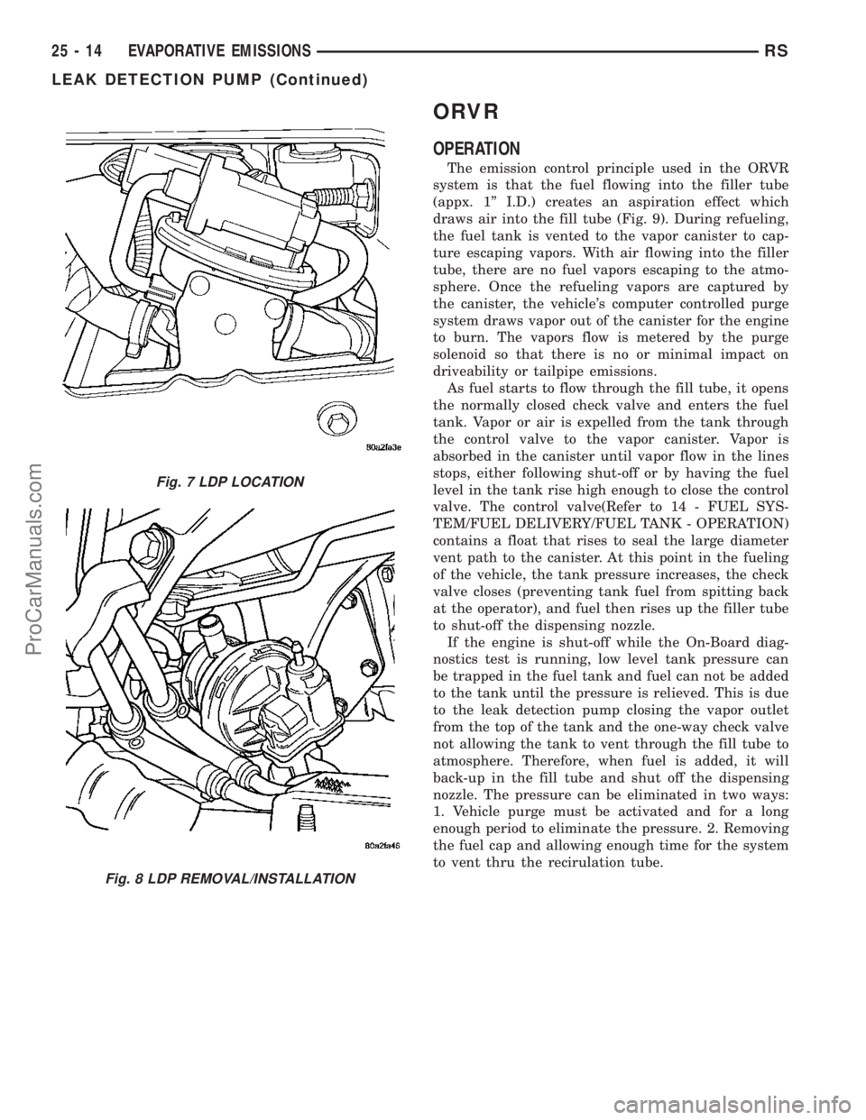
ORVR
OPERATION
The emission control principle used in the ORVR
system is that the fuel flowing into the filler tube
(appx. 1º I.D.) creates an aspiration effect which
draws air into the fill tube (Fig. 9). During refueling,
the fuel tank is vented to the vapor canister to cap-
ture escaping vapors. With air flowing into the filler
tube, there are no fuel vapors escaping to the atmo-
sphere. Once the refueling vapors are captured by
the canister, the vehicle's computer controlled purge
system draws vapor out of the canister for the engine
to burn. The vapors flow is metered by the purge
solenoid so that there is no or minimal impact on
driveability or tailpipe emissions.
As fuel starts to flow through the fill tube, it opens
the normally closed check valve and enters the fuel
tank. Vapor or air is expelled from the tank through
the control valve to the vapor canister. Vapor is
absorbed in the canister until vapor flow in the lines
stops, either following shut-off or by having the fuel
level in the tank rise high enough to close the control
valve. The control valve(Refer to 14 - FUEL SYS-
TEM/FUEL DELIVERY/FUEL TANK - OPERATION)
contains a float that rises to seal the large diameter
vent path to the canister. At this point in the fueling
of the vehicle, the tank pressure increases, the check
valve closes (preventing tank fuel from spitting back
at the operator), and fuel then rises up the filler tube
to shut-off the dispensing nozzle.
If the engine is shut-off while the On-Board diag-
nostics test is running, low level tank pressure can
be trapped in the fuel tank and fuel can not be added
to the tank until the pressure is relieved. This is due
to the leak detection pump closing the vapor outlet
from the top of the tank and the one-way check valve
not allowing the tank to vent through the fill tube to
atmosphere. Therefore, when fuel is added, it will
back-up in the fill tube and shut off the dispensing
nozzle. The pressure can be eliminated in two ways:
1. Vehicle purge must be activated and for a long
enough period to eliminate the pressure. 2. Removing
the fuel cap and allowing enough time for the system
to vent thru the recirulation tube.
Fig. 7 LDP LOCATION
Fig. 8 LDP REMOVAL/INSTALLATION
25 - 14 EVAPORATIVE EMISSIONSRS
LEAK DETECTION PUMP (Continued)
ProCarManuals.com
Page 2127 of 2177
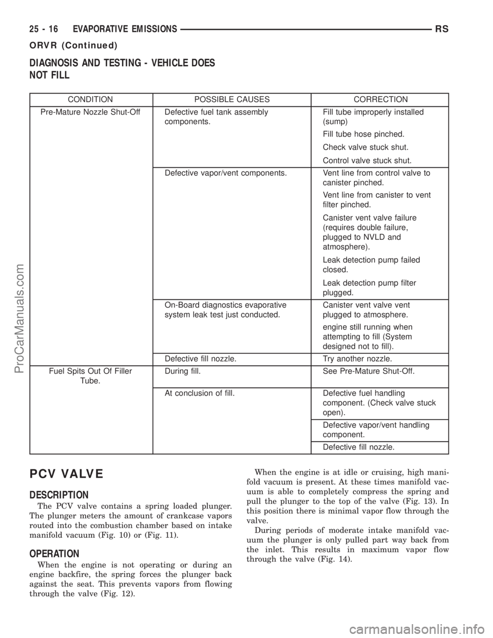
DIAGNOSIS AND TESTING - VEHICLE DOES
NOT FILL
CONDITION POSSIBLE CAUSES CORRECTION
Pre-Mature Nozzle Shut-Off Defective fuel tank assembly
components.Fill tube improperly installed
(sump)
Fill tube hose pinched.
Check valve stuck shut.
Control valve stuck shut.
Defective vapor/vent components. Vent line from control valve to
canister pinched.
Vent line from canister to vent
filter pinched.
Canister vent valve failure
(requires double failure,
plugged to NVLD and
atmosphere).
Leak detection pump failed
closed.
Leak detection pump filter
plugged.
On-Board diagnostics evaporative
system leak test just conducted.Canister vent valve vent
plugged to atmosphere.
engine still running when
attempting to fill (System
designed not to fill).
Defective fill nozzle. Try another nozzle.
Fuel Spits Out Of Filler
Tube.During fill. See Pre-Mature Shut-Off.
At conclusion of fill. Defective fuel handling
component. (Check valve stuck
open).
Defective vapor/vent handling
component.
Defective fill nozzle.
PCV VALVE
DESCRIPTION
The PCV valve contains a spring loaded plunger.
The plunger meters the amount of crankcase vapors
routed into the combustion chamber based on intake
manifold vacuum (Fig. 10) or (Fig. 11).
OPERATION
When the engine is not operating or during an
engine backfire, the spring forces the plunger back
against the seat. This prevents vapors from flowing
through the valve (Fig. 12).When the engine is at idle or cruising, high mani-
fold vacuum is present. At these times manifold vac-
uum is able to completely compress the spring and
pull the plunger to the top of the valve (Fig. 13). In
this position there is minimal vapor flow through the
valve.
During periods of moderate intake manifold vac-
uum the plunger is only pulled part way back from
the inlet. This results in maximum vapor flow
through the valve (Fig. 14).
25 - 16 EVAPORATIVE EMISSIONSRS
ORVR (Continued)
ProCarManuals.com
Page 2148 of 2177
CUSHION SIDE COVER - INSTALLATION,
FRONT SEAT........................23-93
CUSHION SIDE COVER - REMOVAL,
FRONT SEAT........................23-93
CV BOOT - INNER - INSTALLATION........3-6
CV BOOT - INNER - REMOVAL............3-6
CV BOOT - INNER/OUTER -
INSTALLATION........................3-17
CV BOOT - INNER/OUTER - REMOVAL.....3-15
CV BOOT - OUTER - INSTALLATION.......3-10
CV BOOT - OUTER - REMOVAL...........3-10
CYCLE - STANDARD PROCEDURE,
POWER DOOR LEARN................8N-28
CYCLE - STANDARD PROCEDURE,
POWER LIFTGATE LEARN...............8N-9
CYLINDER - DESCRIPTION, KEY/LOCK....19-20
CYLINDER - DESCRIPTION, STANDARD 4 . . . 8I-9
CYLINDER - INSTALLATION, KEY/LOCK . . . 19-20
CYLINDER - INSTALLATION, LOCK . . 23-20,23-41
CYLINDER - INSTALLATION, SLAVE.......6-11
CYLINDER - INSTALLATION, SUPPORT....23-42
CYLINDER - LHD - INSTALLATION,
MASTER............................6-10
CYLINDER - LHD - REMOVAL, MASTER.....6-9
CYLINDER - OPERATION, KEY/LOCK......19-20
CYLINDER - REMOVAL, KEY/LOCK.......19-20
CYLINDER - REMOVAL, LOCK......23-19,23-41
CYLINDER - REMOVAL, SLAVE...........6-11
CYLINDER - REMOVAL, SUPPORT.......23-42
CYLINDER - RHD - INSTALLATION,
MASTER.............................6-9
CYLINDER - RHD - REMOVAL, MASTER.....6-8
CYLINDER BLEEDING - STANDARD
PROCEDURE, MASTER.................5-35
CYLINDER BORE FITTING - STANDARD
PROCEDURE, PISTON TO...............9-42
CYLINDER BORE HONING - STANDARD
PROCEDURE....................9-112,9-35
CYLINDER COMBUSTION PRESSURE
LEAKAGE TEST - DIAGNOSIS AND
TESTING.........................9-83,9-9
CYLINDER COMPRESSION PRESSURE
TEST - DIAGNOSIS AND TESTING.....9-83,9-9
CYLINDER (FLUID RESERVOIR) -
ASSEMBLY, MASTER...................5-38
CYLINDER (FLUID RESERVOIR) -
DISASSEMBLY, MASTER................5-37
CYLINDER HEAD - CLEANING.......9-100,9-26
CYLINDER HEAD - DESCRIPTION.....9-24,9-99
CYLINDER HEAD - INSPECTION.....9-101,9-26
CYLINDER HEAD - INSTALLATION . . . 9-101,9-26
CYLINDER HEAD - REMOVAL.......9-100,9-25
CYLINDER HEAD COVER - CLEANING......9-31
CYLINDER HEAD COVER - INSPECTION....9-31
CYLINDER HEAD COVER -
INSTALLATION........................9-31
CYLINDER HEAD COVER - LEFT -
INSTALLATION.......................9-103
CYLINDER HEAD COVER - LEFT -
REMOVAL..........................9-103
CYLINDER HEAD COVER - REMOVAL......9-31
CYLINDER HEAD COVER - RIGHT -
INSTALLATION.......................9-103
CYLINDER HEAD COVER - RIGHT -
REMOVAL..........................9-102
CYLINDER HEAD COVER(S) -
DESCRIPTION.......................9-102
CYLINDER HEAD GASKET - DIAGNOSIS
AND TESTING....................9-24,9-99
CYLINDER HEAD OFF - INSTALLATION . . . 9-108,
9-33
CYLINDER HEAD OFF - REMOVAL . . . 9-106,9-32
CYLINDER HEAD ON - INSTALLATION....9-108,
9-33
CYLINDER HEAD ON - REMOVAL....9-106,9-32
CYLINDER HOUSING - INSTALLATION,
LOCK..............................19-19
CYLINDER HOUSING - REMOVAL, LOCK . . 19-17
CYLINDER LOCK SWITCH -
DESCRIPTION, DOOR
.................8N-40
CYLINDER LOCK SWITCH - DIAGNOSIS
AND TESTING, DOOR
.................8N-40
CYLINDER LOCK SWITCH -
INSTALLATION, DOOR
.................8N-41
CYLINDER LOCK SWITCH - OPERATION,
DOOR
.............................8N-40
CYLINDER LOCK SWITCH - REMOVAL,
DOOR
.............................8N-41CYLINDERS - INSPECTION, WHEEL.......5-57
CYLINDERS - INSTALLATION, WHEEL.....5-57
CYLINDERS - REMOVAL, WHEEL.........5-57
DAMAGED OR WORN THREADS -
STANDARD PROCEDURE, REPAIR OF . . 9-10,9-86
DAMPER - INSTALLATION, VIBRATION . . . 9-130,
9-47
DAMPER - REMOVAL, VIBRATION . . . 9-130,9-47
DATA BUS COMMUNICATION RECEIVE -
PCM INPUT - OPERATION..............8E-15
DATA LINK CONNECTOR - DESCRIPTION . . . 8E-6
DATA LINK CONNECTOR - OPERATION.....8E-7
DAY / NIGHT MIRROR - DESCRIPTION,
AUTOMATIC........................8N-47
DAY / NIGHT MIRROR - DIAGNOSIS AND
TESTING, AUTOMATIC................8N-47
DAY / NIGHT MIRROR - OPERATION,
AUTOMATIC........................8N-47
DCHA - DIAGNOSIS AND TESTING,
DIESEL SUPPLEMENTAL HEATER.......24-107
DCHA - EXPORT - DESCRIPTION, DIESEL
SUPPLEMENTAL HEATER.............24-106
DEAERATION - DIAGNOSIS AND
TESTING, COOLING SYSTEM.............7-4
DECOUPLER PULLEY - DESCRIPTION,
GENERATOR........................8F-25
DECOUPLER PULLEY - DIAGNOSIS AND
TESTING, GENERATOR................8F-25
DECOUPLER PULLEY - INSTALLATION,
GENERATOR........................8F-26
DECOUPLER PULLEY - OPERATION,
GENERATOR..........................8F-25
DECOUPLER PULLEY - REMOVAL,
GENERATOR........................8F-26
DEFINITION - DESCRIPTION, TRIP........25-1
DEFLECTOR - INSTALLATION, WIND.....23-118
DEFLECTOR - REMOVAL, WIND........23-118
DEFOGGER RELAY - DESCRIPTION.......8G-2
DEFOGGER SWITCH - DESCRIPTION,
REAR WINDOW.......................8G-2
DEFOGGER SWITCH - OPERATION, REAR
WINDOW............................8G-2
DEFROSTER DUCT - INSTALLATION......24-48
DEFROSTER DUCT - REMOVAL..........24-47
DEMAGNETIZING - STANDARD
PROCEDURE, COMPASS...............8M-4
DEMISTER DUCTS - INSTALLATION......24-48
DEMISTER DUCTS - REMOVAL..........24-48
DEMISTER OUTLET - INSTALLATION.....24-42
DEMISTER OUTLET - REMOVAL.........24-41
DEPLOYMENT - STANDARD
PROCEDURE, SERVICE AFTER AN
AIRBAG.............................8O-3
DETECTION ASSY - INSTALLATION,
NATURAL VAC LEAK..................25-13
DETECTION ASSY - REMOVAL, NATURAL
VAC LEAK..........................25-13
DETECTION PUMP - INSTALLATION,
LEAK..............................25-13
DETECTION PUMP - REMOVAL, LEAK....25-13
DEVICES - STANDARD PROCEDURE,
ELECTROSTATIC DISCHARGE (ESD)
SENSITIVE........................8W-01-8
DIAGNOSTIC SYSTEM - DIAGNOSIS AND
TESTING, ON-BOARD.................8F-21
DIAGNOSTIC TROUBLE CODES -
STANDARD PROCEDURE, OBTAINING.....8E-15
DIAGRAMS - 41TE TRANSAXLE
HYDRAULIC SCHEMATICS,
SCHEMATICS.......................21-169
DIAGRAMS - DESCRIPTION, HOW TO
USE WIRING......................8W-01-1
DIESEL - DESCRIPTION, 2.5L...........19-51
DIESEL - INSTALLATION, 2.5L..........19-52
DIESEL - REMOVAL, 2.5L..............19-51
DIESEL ENGINE - DESCRIPTION, FUEL
REQUIREMENTS.......................0-6
DIESEL ENGINES - DESCRIPTION,
ENGINE OIL...........................0-6
DIESEL HEATER WIRING -
INSTALLATION, SUPPLEMENTAL
........24-112
DIESEL HEATER WIRING - REMOVAL,
SUPPLEMENTAL
....................24-112
DIESEL SUPPLEMENTAL HEATER - DCHA
- DIAGNOSIS AND TESTING
...........24-107
DIESEL SUPPLEMENTAL HEATER - DCHA
- EXPORT - DESCRIPTION
............24-106
DIFFERENTIAL - ASSEMBLY
............21-66DIFFERENTIAL - DESCRIPTION..........21-62
DIFFERENTIAL - DISASSEMBLY.........21-62
DIFFERENTIAL - OPERATION............21-62
DIFFERENTIAL ASSEMBLY -
DESCRIPTION........................3-39
DIFFERENTIAL ASSEMBLY - OPERATION . . . 3-39
DIFFERENTIAL ASSEMBLY FLUID
CHANGE - STANDARD PROCEDURE.......3-40
DIFFERENTIAL BEARING PRELOAD -
ADJUSTMENT......................21-199
DIFFERENTIAL CARRIER SEAL -
INSTALLATION........................21-9
DIFFERENTIAL CARRIER SEAL -
REMOVAL...........................21-9
DIFFERENTIAL SIDE GEAR END PLAY -
ADJUSTMENT.......................21-70
DIFFERENTIAL TURNING TORQUE -
ADJUSTMENT.......................21-69
DIMENSIONS - SPECIFICATIONS, BODY
OPENING..........................23-124
DIMENSIONS, SPECIFICATIONS - FRAME . . . 13-4
DIODE - INSTALLATION............8W-01-14
DIODE - REMOVAL................8W-01-14
DISC AND PRESSURE PLATE - 2.5L TD -
INSTALLATION, CLUTCH................6-12
DISC AND PRESSURE PLATE - 2.5L TD -
REMOVAL, CLUTCH....................6-11
DISC BRAKE CALIPER - INSTALLATION,
REAR...............................5-30
DISC BRAKE CALIPER - REMOVAL,
REAR...............................5-27
DISC BRAKE CALIPER ADAPTER -
INSTALLATION, FRONT.................5-31
DISC BRAKE CALIPER ADAPTER -
REMOVAL, FRONT.....................5-31
DISC BRAKE CALIPER (DISC/DISC
BRAKES) - INSTALLATION, FRONT........5-27
DISC BRAKE CALIPER (DISC/DISC
BRAKES) - REMOVAL, FRONT............5-24
DISC BRAKE CALIPER (DISC/DRUM
BRAKES) - INSTALLATION, FRONT........5-27
DISC BRAKE CALIPER (DISC/DRUM
BRAKES) - REMOVAL, FRONT............5-24
DISC BRAKE CALIPER GUIDE PINS
(DISC/DRUM BRAKES) -
INSTALLATION........................5-31
DISC BRAKE CALIPER GUIDE PINS
(DISC/DRUM BRAKES) - REMOVAL.......5-31
DISC BRAKE SHOES - CLEANING.....5-16,5-18
DISC BRAKE SHOES - INSPECTION . . . 5-16,5-18
DISC BRAKE SHOES - INSTALLATION,
REAR...............................5-19
DISC BRAKE SHOES - REMOVAL, REAR....5-17
DISC BRAKE SHOES (DISC/DISC
BRAKES) - INSTALLATION, FRONT........5-16
DISC BRAKE SHOES (DISC/DISC
BRAKES) - REMOVAL, FRONT............5-14
DISC BRAKE SHOES (DISC/DRUM
BRAKES) - INSTALLATION, FRONT........5-17
DISC BRAKE SHOES (DISC/DRUM
BRAKES) - REMOVAL, FRONT............5-15
DISC BRAKES (EXPORT) - DESCRIPTION . . . 5-13
DISC BRAKES (FRONT) - DESCRIPTION....5-11
DISC BRAKES (FRONT) - OPERATION......5-13
DISC BRAKES (REAR) - DESCRIPTION.....5-12
DISC BRAKES (REAR) - OPERATION......5-13
DISC RUNOUT - DIAGNOSIS AND
TESTING, CLUTCH COVER...............6-6
DISCHARGE (ESD) SENSITIVE DEVICES -
STANDARD PROCEDURE,
ELECTROSTATIC...................8W-01-8
DISCHARGE LINE - INSTALLATION.......24-69
DISCHARGE LINE - REMOVAL..........24-68
DISPLAY TEST MODE, OPERATION - DRB
IIITSTATE ...........................25-9
DISTRIBUTION DUCT - INSTALLATION,
A/C................................24-53
DISTRIBUTION DUCT - INSTALLATION,
REAR HEATER.......................24-59
DISTRIBUTION DUCT - REMOVAL, A/C
....24-53
DISTRIBUTION DUCT - REMOVAL, REAR
HEATER
............................24-59
DISTRIBUTION DUCTS - INSTALLATION,
FLOOR
.............................24-49
DISTRIBUTION DUCTS - REMOVAL,
FLOOR
.............................24-48
DISTRIBUTION SYSTEM - DESCRIPTION,
POWER
..........................8W-97-1
RSINDEX9
Description Group-Page Description Group-Page Description Group-Page
ProCarManuals.com