2003 CHRYSLER CARAVAN oil level
[x] Cancel search: oil levelPage 1422 of 2177
OPERATION
Turning of the steering wheel is converted into lin-
ear (side-to-side) travel through the meshing of the
helical pinion teeth with the rack teeth in the steer-
ing gear. This travel pushes and pulls the tie rods to
change the direction of the vehicle's front wheels.
Power assist steering provided by the power steer-
ing pump is controlled by an open center, rotary type
control valve which directs oil from the pump to
either side of the integral rack piston upon demand.
Road feel is controlled by the diameter of a torsion
bar which initially steers the vehicle. As required
steering effort increases, as in a turn, the torsion bar
twists, causing relative rotary motion between the
rotary valve body and the valve spool. This move-
ment directs oil behind the integral rack piston
which, in turn, builds hydraulic pressure and assists
in the turning effort.
Manual steering control of the vehicle can be main-
tained if power steering assist is lost. However,
under this condition, steering effort is significantly
increased.
WARNING
WARNINGS AND CAUTIONS
WARNING: POWER STEERING FLUID, ENGINE
PARTS AND EXHAUST SYSTEM MAY BE
EXTREMELY HOT IF ENGINE HAS BEEN RUNNING.
DO NOT START ENGINE WITH ANY LOOSE OR DIS-
CONNECTED HOSES. DO NOT ALLOW HOSES TO
TOUCH HOT EXHAUST MANIFOLD OR CATALYST.
WARNING: FLUID LEVEL SHOULD BE CHECKED
WITH THE ENGINE OFF TO PREVENT PERSONAL
INJURY FROM MOVING PARTS.
CAUTION: When the system is open, cap all open
ends of the hoses, power steering pump fittings or
power steering gear ports to prevent entry of for-
eign material into the components.
REMOVAL
REMOVAL - LHD GEAR
(1) Remove cap from power steering fluid reser-
voir.
(2) Using a siphon pump, remove as much fluid as
possible from the power steering fluid reservoir.Use
care not to damage the filter mesh below the
fluid surface.
CAUTION: Locking the steering column in the
straight-ahead position will prevent the clockspring
from being accidentally over-extended when the
steering column is disconnected from the interme-
diate steering coupler.
(3) Position the steering wheel in the STRAIGHT-
AHEAD position. Lock the steering wheel in place
using a steering wheel holding tool.
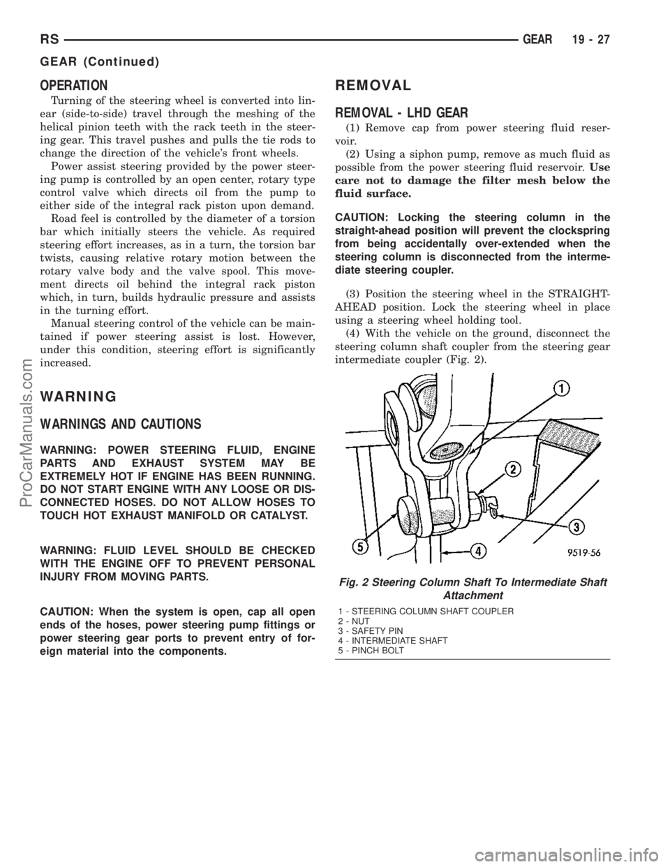
(4) With the vehicle on the ground, disconnect the
steering column shaft coupler from the steering gear
intermediate coupler (Fig. 2).
Fig. 2 Steering Column Shaft To Intermediate Shaft
Attachment
1 - STEERING COLUMN SHAFT COUPLER
2 - NUT
3 - SAFETY PIN
4 - INTERMEDIATE SHAFT
5 - PINCH BOLT
RSGEAR19-27
GEAR (Continued)
ProCarManuals.com
Page 1448 of 2177
TRANSMISSION/TRANSAXLE
TABLE OF CONTENTS
page page
POWER TRANSFER UNIT..................1
T850 MANUAL TRANSAXLE...............2141TE AUTOMATIC TRANSAXLE............116
POWER TRANSFER UNIT
TABLE OF CONTENTS
page page
POWER TRANSFER UNIT
DESCRIPTION..........................1
OPERATION............................3
DIAGNOSIS AND TESTING
SEAL IDENTIFICATION..................3
FLUID LEAK DIAGNOSIS................3
STANDARD PROCEDURE
STANDARD PROCEDURE - FLUID LEVEL
INSPECTION..........................4
STANDARD PROCEDURE - PTU FLUID
CHANGE.............................5
REMOVAL.............................5
INSTALLATION..........................6
ADJUSTMENTS
OUTPUT FLANGE SHIM SELECTION.......7
SPECIFICATIONS
TORQUE.............................7
SPECIAL TOOLS
SDP POWER TRANSFER UNIT............8
DIFFERENTIAL CARRIER SEAL
REMOVAL.............................9
INSTALLATION..........................9
END COVER BALL BEARING
REMOVAL.............................9INSTALLATION.........................10
END COVER SEAL
REMOVAL.............................11
INSTALLATION.........................11
HALF SHAFT INNER SEAL
REMOVAL.............................12
INSTALLATION.........................12
INPUT SHAFT COVER SEAL
REMOVAL.............................13
INSTALLATION.........................14
INPUT SHAFT END SEAL
REMOVAL.............................15
INSTALLATION.........................16
INPUT SHAFT SEAL
REMOVAL.............................17
INSTALLATION.........................18
OUTER HALF SHAFT SEAL
REMOVAL.............................19
INSTALLATION.........................19
REAR COVER O-RING
REMOVAL.............................19
INSTALLATION.........................20
POWER TRANSFER UNIT
DESCRIPTION
The Power Transfer Unit (P.T.U.) is attached to a
modified automatic transaxle case where the right
half shaft extension housing would normally be
located.
The Power Transfer Unit is sealed from the trans-
axle and has its own oil sump. The Unit uses MopartSAE 80W-90 Gear and Axle Lubricant (MS-9020) and
holds 1.15 liters (1.22 quarts).
Service of the Power Transfer Unit is limited to:
²Fluid Change
²Seals
²Gaskets
²One ball bearing
²Output flange
If the ring gear and pinion, any tapered roller
bearings, case, covers, or pinion carrier fail the entire
unit must be replaced.
RSTRANSMISSION/TRANSAXLE21-1
ProCarManuals.com
Page 1451 of 2177
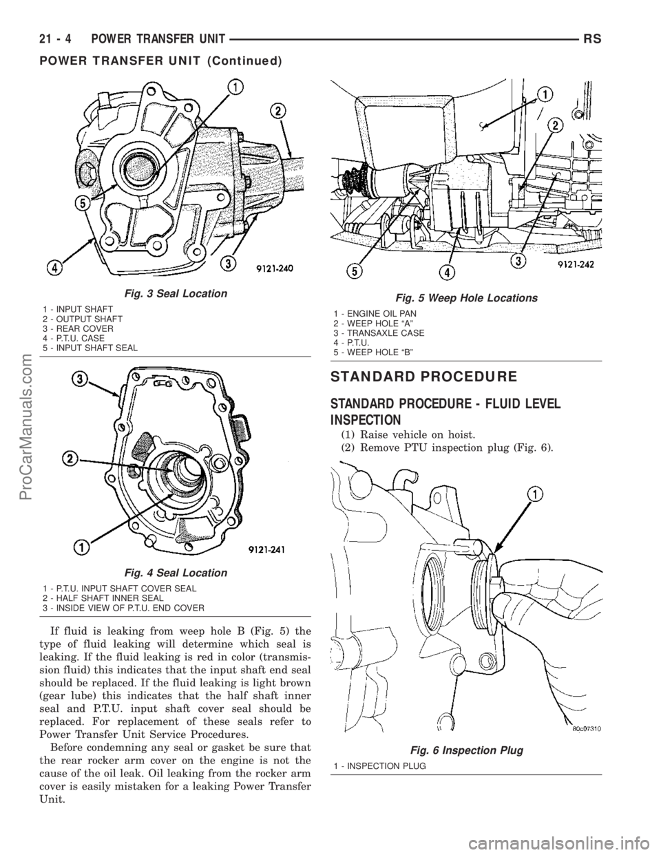
If fluid is leaking from weep hole B (Fig. 5) the
type of fluid leaking will determine which seal is
leaking. If the fluid leaking is red in color (transmis-
sion fluid) this indicates that the input shaft end seal
should be replaced. If the fluid leaking is light brown
(gear lube) this indicates that the half shaft inner
seal and P.T.U. input shaft cover seal should be
replaced. For replacement of these seals refer to
Power Transfer Unit Service Procedures.
Before condemning any seal or gasket be sure that
the rear rocker arm cover on the engine is not the
cause of the oil leak. Oil leaking from the rocker arm
cover is easily mistaken for a leaking Power Transfer
Unit.
STANDARD PROCEDURE
STANDARD PROCEDURE - FLUID LEVEL
INSPECTION
(1) Raise vehicle on hoist.
(2) Remove PTU inspection plug (Fig. 6).
Fig. 3 Seal Location
1 - INPUT SHAFT
2 - OUTPUT SHAFT
3 - REAR COVER
4 - P.T.U. CASE
5 - INPUT SHAFT SEAL
Fig. 4 Seal Location
1 - P.T.U. INPUT SHAFT COVER SEAL
2 - HALF SHAFT INNER SEAL
3 - INSIDE VIEW OF P.T.U. END COVER
Fig. 5 Weep Hole Locations
1 - ENGINE OIL PAN
2 - WEEP HOLE ªAº
3 - TRANSAXLE CASE
4 - P.T.U.
5 - WEEP HOLE ªBº
Fig. 6 Inspection Plug
1 - INSPECTION PLUG
21 - 4 POWER TRANSFER UNITRS
POWER TRANSFER UNIT (Continued)
ProCarManuals.com
Page 1452 of 2177
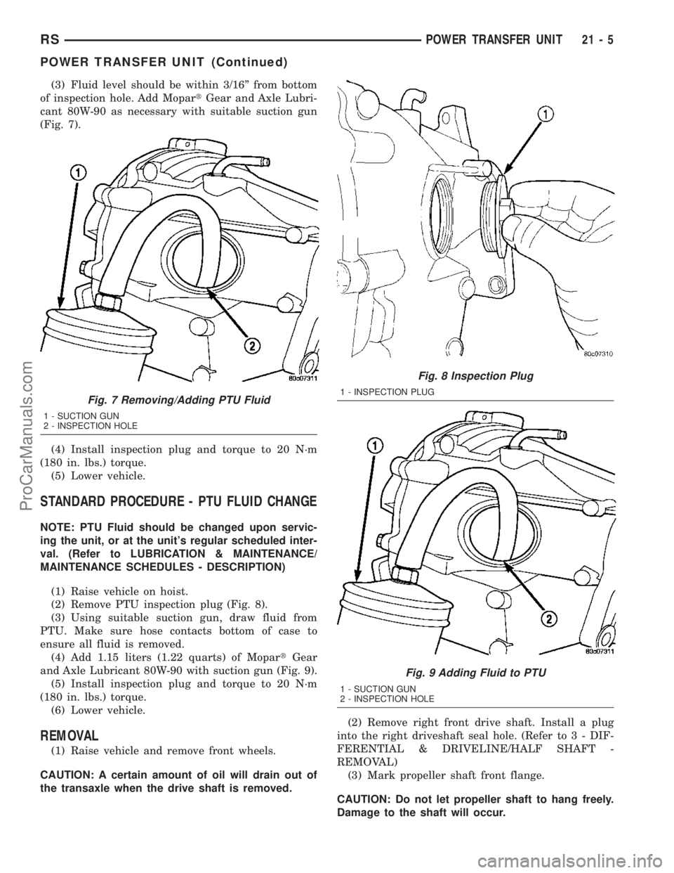
(3) Fluid level should be within 3/16º from bottom
of inspection hole. Add MopartGear and Axle Lubri-
cant 80W-90 as necessary with suitable suction gun
(Fig. 7).
(4) Install inspection plug and torque to 20 N´m
(180 in. lbs.) torque.
(5) Lower vehicle.
STANDARD PROCEDURE - PTU FLUID CHANGE
NOTE: PTU Fluid should be changed upon servic-
ing the unit, or at the unit's regular scheduled inter-
val. (Refer to LUBRICATION & MAINTENANCE/
MAINTENANCE SCHEDULES - DESCRIPTION)
(1) Raise vehicle on hoist.
(2) Remove PTU inspection plug (Fig. 8).
(3) Using suitable suction gun, draw fluid from
PTU. Make sure hose contacts bottom of case to
ensure all fluid is removed.
(4) Add 1.15 liters (1.22 quarts) of MopartGear
and Axle Lubricant 80W-90 with suction gun (Fig. 9).
(5) Install inspection plug and torque to 20 N´m
(180 in. lbs.) torque.
(6) Lower vehicle.
REMOVAL
(1) Raise vehicle and remove front wheels.
CAUTION: A certain amount of oil will drain out of
the transaxle when the drive shaft is removed.(2) Remove right front drive shaft. Install a plug
into the right driveshaft seal hole. (Refer to 3 - DIF-
FERENTIAL & DRIVELINE/HALF SHAFT -
REMOVAL)
(3) Mark propeller shaft front flange.
CAUTION: Do not let propeller shaft to hang freely.
Damage to the shaft will occur.
Fig. 7 Removing/Adding PTU Fluid
1 - SUCTION GUN
2 - INSPECTION HOLE
Fig. 8 Inspection Plug
1 - INSPECTION PLUG
Fig. 9 Adding Fluid to PTU
1 - SUCTION GUN
2 - INSPECTION HOLE
RSPOWER TRANSFER UNIT21-5
POWER TRANSFER UNIT (Continued)
ProCarManuals.com
Page 1478 of 2177
Misassembled synchronizer components also cause
shifting problems. Incorrectly installed synchronizer
sleeves, keys, balls, or springs can cause shift prob-
lems.
NOISY OPERATION
Transaxle noise is most often a result of worn or
damaged components. Chipped, broken gear or syn-
chronizer teeth, and brinnelled, spalled bearings all
cause noise.
Abnormal wear and damage to the internal compo-
nents is frequently the end result of insufficient
lubricant.
SLIPS OUT OF GEAR
Transaxle disengagement may be caused by mis-
aligned or damaged shift components, or worn teeth
on the drive gears or synchronizer components. Incor-
rect assembly also causes gear disengagement. Check
for missing snap rings.
LOW LUBRICANT LEVEL
Insufficient transaxle lubricant is usually the
result of leaks, or inaccurate fluid level check or refill
method. Leakage is evident by the presence of oil
around the leak point. If leakage is not evident, the
condition is probably the result of an underfill.
If air±powered lubrication equipment is used to fill
a transaxle, be sure the equipment is properly cali-
brated. Equipment out of calibration can lead to an
underfill condition.
CLUTCH PROBLEMS
Worn, damaged, or misaligned clutch components
can cause difficult shifting, gear clash, and noise.
A worn or damaged clutch disc, pressure plate, or
release bearing can cause hard shifting and gear
clash.
REMOVAL
REMOVAL - 2.4L GAS
(1) Raise hood.
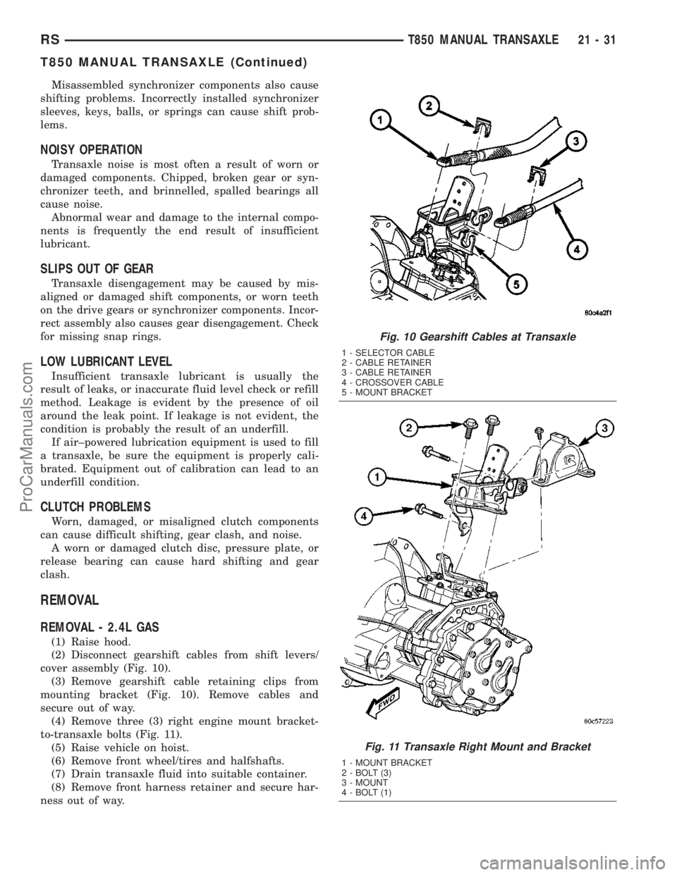
(2) Disconnect gearshift cables from shift levers/
cover assembly (Fig. 10).
(3) Remove gearshift cable retaining clips from
mounting bracket (Fig. 10). Remove cables and
secure out of way.
(4) Remove three (3) right engine mount bracket-
to-transaxle bolts (Fig. 11).
(5) Raise vehicle on hoist.
(6) Remove front wheel/tires and halfshafts.
(7) Drain transaxle fluid into suitable container.
(8) Remove front harness retainer and secure har-
ness out of way.
Fig. 10 Gearshift Cables at Transaxle
1 - SELECTOR CABLE
2 - CABLE RETAINER
3 - CABLE RETAINER
4 - CROSSOVER CABLE
5 - MOUNT BRACKET
Fig. 11 Transaxle Right Mount and Bracket
1 - MOUNT BRACKET
2 - BOLT (3)
3 - MOUNT
4 - BOLT (1)
RST850 MANUAL TRANSAXLE21-31
T850 MANUAL TRANSAXLE (Continued)
ProCarManuals.com
Page 1563 of 2177
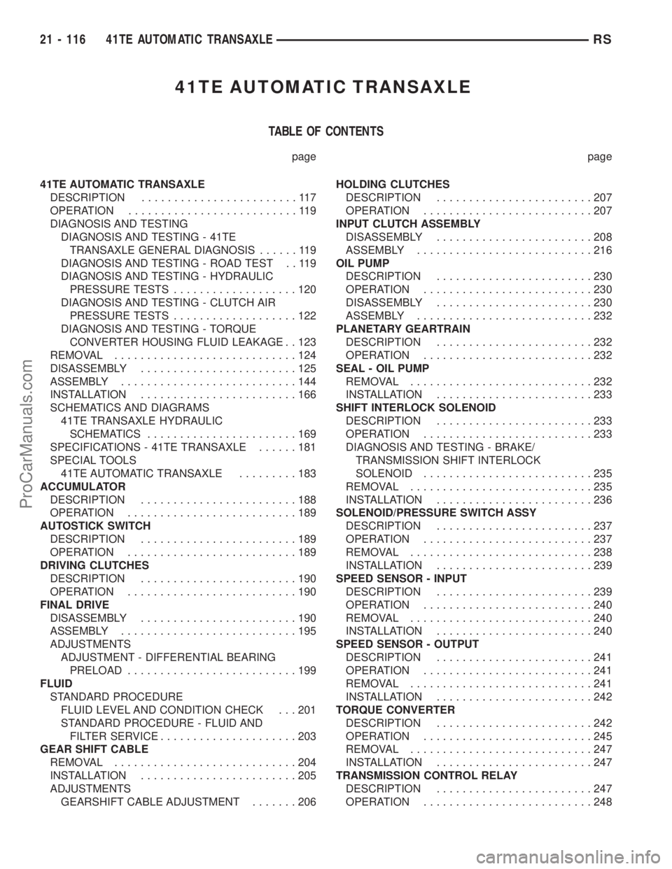
41TE AUTOMATIC TRANSAXLE
TABLE OF CONTENTS
page page
41TE AUTOMATIC TRANSAXLE
DESCRIPTION........................117
OPERATION..........................119
DIAGNOSIS AND TESTING
DIAGNOSIS AND TESTING - 41TE
TRANSAXLE GENERAL DIAGNOSIS......119
DIAGNOSIS AND TESTING - ROAD TEST . . 119
DIAGNOSIS AND TESTING - HYDRAULIC
PRESSURE TESTS...................120
DIAGNOSIS AND TESTING - CLUTCH AIR
PRESSURE TESTS...................122
DIAGNOSIS AND TESTING - TORQUE
CONVERTER HOUSING FLUID LEAKAGE . . 123
REMOVAL............................124
DISASSEMBLY........................125
ASSEMBLY...........................144
INSTALLATION........................166
SCHEMATICS AND DIAGRAMS
41TE TRANSAXLE HYDRAULIC
SCHEMATICS.......................169
SPECIFICATIONS - 41TE TRANSAXLE......181
SPECIAL TOOLS
41TE AUTOMATIC TRANSAXLE.........183
ACCUMULATOR
DESCRIPTION........................188
OPERATION..........................189
AUTOSTICK SWITCH
DESCRIPTION........................189
OPERATION..........................189
DRIVING CLUTCHES
DESCRIPTION........................190
OPERATION..........................190
FINAL DRIVE
DISASSEMBLY........................190
ASSEMBLY...........................195
ADJUSTMENTS
ADJUSTMENT - DIFFERENTIAL BEARING
PRELOAD..........................199
FLUID
STANDARD PROCEDURE
FLUID LEVEL AND CONDITION CHECK . . . 201
STANDARD PROCEDURE - FLUID AND
FILTER SERVICE.....................203
GEAR SHIFT CABLE
REMOVAL............................204
INSTALLATION........................205
ADJUSTMENTS
GEARSHIFT CABLE ADJUSTMENT.......206HOLDING CLUTCHES
DESCRIPTION........................207
OPERATION..........................207
INPUT CLUTCH ASSEMBLY
DISASSEMBLY........................208
ASSEMBLY...........................216
OIL PUMP
DESCRIPTION........................230
OPERATION..........................230
DISASSEMBLY........................230
ASSEMBLY...........................232
PLANETARY GEARTRAIN
DESCRIPTION........................232
OPERATION..........................232
SEAL - OIL PUMP
REMOVAL............................232
INSTALLATION........................233
SHIFT INTERLOCK SOLENOID
DESCRIPTION........................233
OPERATION..........................233
DIAGNOSIS AND TESTING - BRAKE/
TRANSMISSION SHIFT INTERLOCK
SOLENOID..........................235
REMOVAL............................235
INSTALLATION........................236
SOLENOID/PRESSURE SWITCH ASSY
DESCRIPTION........................237
OPERATION..........................237
REMOVAL............................238
INSTALLATION........................239
SPEED SENSOR - INPUT
DESCRIPTION........................239
OPERATION..........................240
REMOVAL............................240
INSTALLATION........................240
SPEED SENSOR - OUTPUT
DESCRIPTION........................241
OPERATION..........................241
REMOVAL............................241
INSTALLATION........................242
TORQUE CONVERTER
DESCRIPTION........................242
OPERATION..........................245
REMOVAL............................247
INSTALLATION........................247
TRANSMISSION CONTROL RELAY
DESCRIPTION........................247
OPERATION..........................248
21 - 116 41TE AUTOMATIC TRANSAXLERS
ProCarManuals.com
Page 1570 of 2177
LOW/REVERSE CLUTCH
Apply air pressure to the low/reverse clutch feed
hole (rear of case, between 2 bolt holes). Then, look
in the area where the low/reverse piston contacts the
first separator plate. Watch carefully for the piston to
move forward. The piston should return to its origi-
nal position after the air pressure is removed.
UNDERDRIVE CLUTCH
Because this clutch piston cannot be seen, its oper-
ation is checked by function. Air pressure is applied
to the low/reverse and the 2/4 clutches. This locks the
output shaft. Use a piece of rubber hose wrapped
around the input shaft and a pair of clamp-on pliers
to turn the input shaft. Next apply air pressure to
the underdrive clutch. The input shaft should notrotate with hand torque. Release the air pressure
and confirm that the input shaft will rotate.
DIAGNOSIS AND TESTING - TORQUE
CONVERTER HOUSING FLUID LEAKAGE
When diagnosing converter housing fluid leaks,
three actions must be taken before repair:
(1) Verify proper transmission fluid level.
(2) Verify that the leak originates from the con-
verter housing area and is transmission fluid.
(3) Determine the true source of the leak.
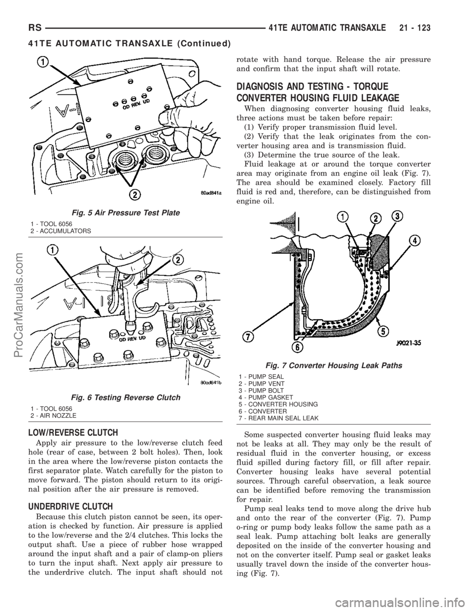
Fluid leakage at or around the torque converter
area may originate from an engine oil leak (Fig. 7).
The area should be examined closely. Factory fill
fluid is red and, therefore, can be distinguished from
engine oil.
Some suspected converter housing fluid leaks may
not be leaks at all. They may only be the result of
residual fluid in the converter housing, or excess
fluid spilled during factory fill, or fill after repair.
Converter housing leaks have several potential
sources. Through careful observation, a leak source
can be identified before removing the transmission
for repair.
Pump seal leaks tend to move along the drive hub
and onto the rear of the converter (Fig. 7). Pump
o-ring or pump body leaks follow the same path as a
seal leak. Pump attaching bolt leaks are generally
deposited on the inside of the converter housing and
not on the converter itself. Pump seal or gasket leaks
usually travel down the inside of the converter hous-
ing (Fig. 7).
Fig. 5 Air Pressure Test Plate
1 - TOOL 6056
2 - ACCUMULATORS
Fig. 6 Testing Reverse Clutch
1 - TOOL 6056
2 - AIR NOZZLE
Fig. 7 Converter Housing Leak Paths
1 - PUMP SEAL
2 - PUMP VENT
3 - PUMP BOLT
4 - PUMP GASKET
5 - CONVERTER HOUSING
6 - CONVERTER
7 - REAR MAIN SEAL LEAK
RS41TE AUTOMATIC TRANSAXLE21 - 123
41TE AUTOMATIC TRANSAXLE (Continued)
ProCarManuals.com
Page 1571 of 2177
TORQUE CONVERTER LEAKAGE
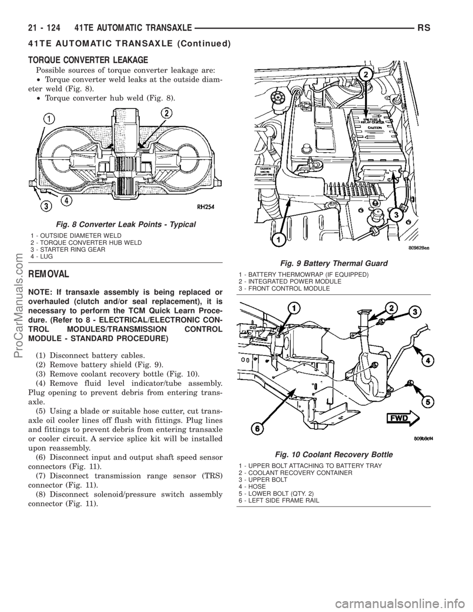
Possible sources of torque converter leakage are:
²Torque converter weld leaks at the outside diam-
eter weld (Fig. 8).
²Torque converter hub weld (Fig. 8).
REMOVAL
NOTE: If transaxle assembly is being replaced or
overhauled (clutch and/or seal replacement), it is
necessary to perform the TCM Quick Learn Proce-
dure. (Refer to 8 - ELECTRICAL/ELECTRONIC CON-
TROL MODULES/TRANSMISSION CONTROL
MODULE - STANDARD PROCEDURE)
(1) Disconnect battery cables.
(2) Remove battery shield (Fig. 9).
(3) Remove coolant recovery bottle (Fig. 10).
(4) Remove fluid level indicator/tube assembly.
Plug opening to prevent debris from entering trans-
axle.
(5) Using a blade or suitable hose cutter, cut trans-
axle oil cooler lines off flush with fittings. Plug lines
and fittings to prevent debris from entering transaxle
or cooler circuit. A service splice kit will be installed
upon reassembly.
(6) Disconnect input and output shaft speed sensor
connectors (Fig. 11).
(7) Disconnect transmission range sensor (TRS)
connector (Fig. 11).
(8) Disconnect solenoid/pressure switch assembly
connector (Fig. 11).
Fig. 8 Converter Leak Points - Typical
1 - OUTSIDE DIAMETER WELD
2 - TORQUE CONVERTER HUB WELD
3 - STARTER RING GEAR
4 - LUG
Fig. 9 Battery Thermal Guard
1 - BATTERY THERMOWRAP (IF EQUIPPED)
2 - INTEGRATED POWER MODULE
3 - FRONT CONTROL MODULE
Fig. 10 Coolant Recovery Bottle
1 - UPPER BOLT ATTACHING TO BATTERY TRAY
2 - COOLANT RECOVERY CONTAINER
3 - UPPER BOLT
4 - HOSE
5 - LOWER BOLT (QTY. 2)
6 - LEFT SIDE FRAME RAIL
21 - 124 41TE AUTOMATIC TRANSAXLERS
41TE AUTOMATIC TRANSAXLE (Continued)
ProCarManuals.com