2003 CHRYSLER CARAVAN timing belt
[x] Cancel search: timing beltPage 1332 of 2177
VALVE TIMING
STANDARD PROCEDURE
STANDARD PROCEDURE - VALVE TIMING
VERIFICATION
(1) Remove front cylinder head cover and all 6
spark plugs.
(2) Rotate engine until the #2 piston is at TDC of
the compression stroke.
(3) Install a degree wheel on the crankshaft pulley.
(4) With proper adaptor, install a dial indicator
into #2 spark plug hole. Using the indicator find TDC
on the compression stroke.
(5) Position the degree wheel to zero.
(6) Remove dial indicator from spark plug hole.
(7) Place a 5.08 mm (0.200 in.) spacer between the
valve stem tip of #2 intake valve and rocker arm pad.
Allow tappet to bleed down to give a solid tappet
effect.
(8) Install a dial indicator so plunger contacts the
#2 intake valve spring retainer as nearly perpendic-
ular as possible. Zero the indicator.
(9) Rotate the engine clockwise until the intake
valve has lifted .254 mm (0.010 in.).
CAUTION: Do not turn crankshaft any further clock-
wise as intake valve might bottom and result in
serious damage.
(10) Degree wheel should read 6 degrees BTDC to
6 degrees ATDC.
STANDARD PROCEDURE - MEASURING
TIMING CHAIN WEAR
NOTE: This procedure must be performed with the
timing chain cover removed (Refer to 9 - ENGINE/
VALVE TIMING/TIMING CHAIN COVER - REMOVAL).
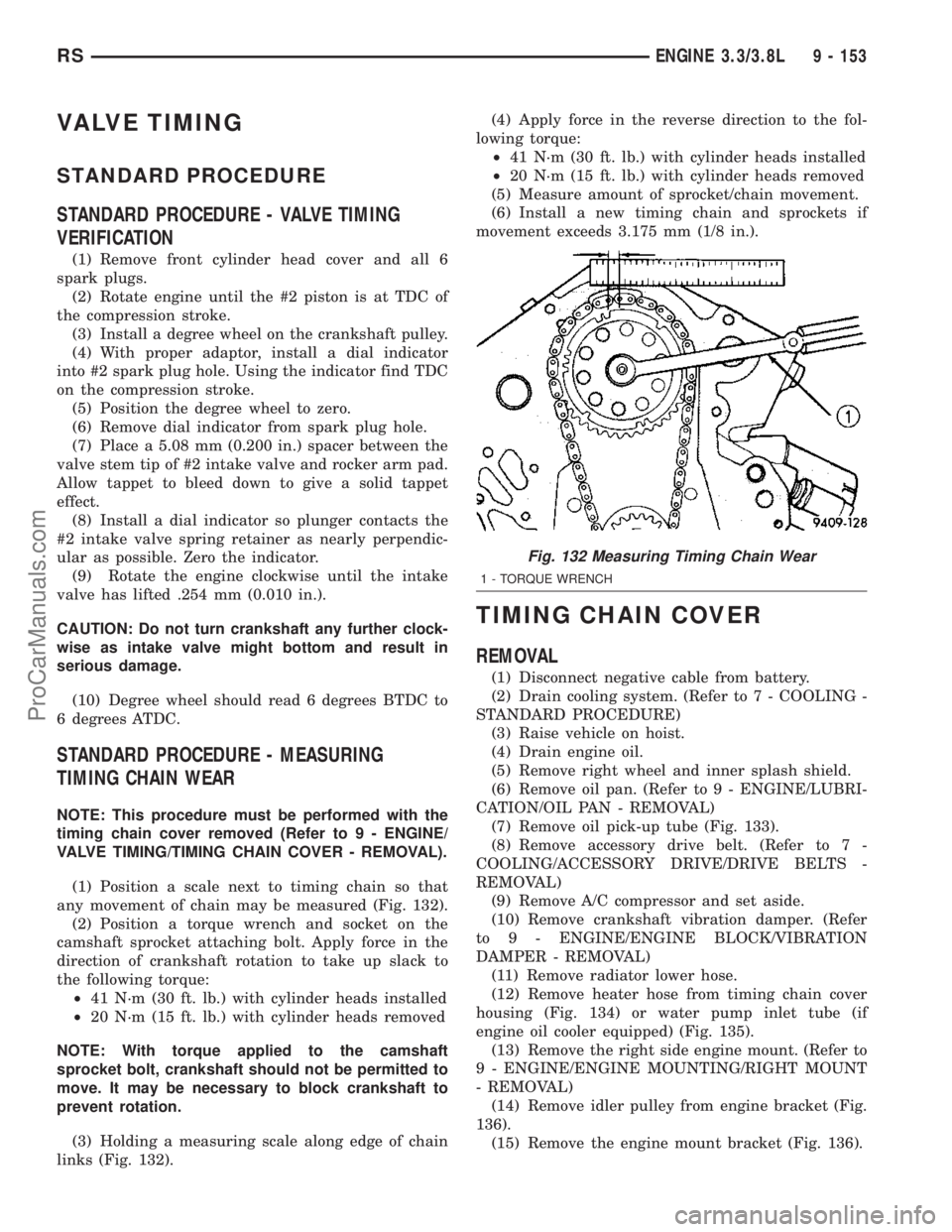
(1) Position a scale next to timing chain so that
any movement of chain may be measured (Fig. 132).
(2) Position a torque wrench and socket on the
camshaft sprocket attaching bolt. Apply force in the
direction of crankshaft rotation to take up slack to
the following torque:
²41 N´m (30 ft. lb.) with cylinder heads installed
²20 N´m (15 ft. lb.) with cylinder heads removed
NOTE: With torque applied to the camshaft
sprocket bolt, crankshaft should not be permitted to
move. It may be necessary to block crankshaft to
prevent rotation.
(3) Holding a measuring scale along edge of chain
links (Fig. 132).(4) Apply force in the reverse direction to the fol-
lowing torque:
²41 N´m (30 ft. lb.) with cylinder heads installed
²20 N´m (15 ft. lb.) with cylinder heads removed
(5) Measure amount of sprocket/chain movement.
(6) Install a new timing chain and sprockets if
movement exceeds 3.175 mm (1/8 in.).
TIMING CHAIN COVER
REMOVAL
(1) Disconnect negative cable from battery.
(2) Drain cooling system. (Refer to 7 - COOLING -
STANDARD PROCEDURE)
(3) Raise vehicle on hoist.
(4) Drain engine oil.
(5) Remove right wheel and inner splash shield.
(6) Remove oil pan. (Refer to 9 - ENGINE/LUBRI-
CATION/OIL PAN - REMOVAL)
(7) Remove oil pick-up tube (Fig. 133).
(8) Remove accessory drive belt. (Refer to 7 -
COOLING/ACCESSORY DRIVE/DRIVE BELTS -
REMOVAL)
(9) Remove A/C compressor and set aside.
(10) Remove crankshaft vibration damper. (Refer
to 9 - ENGINE/ENGINE BLOCK/VIBRATION
DAMPER - REMOVAL)
(11) Remove radiator lower hose.
(12) Remove heater hose from timing chain cover
housing (Fig. 134) or water pump inlet tube (if
engine oil cooler equipped) (Fig. 135).
(13) Remove the right side engine mount. (Refer to
9 - ENGINE/ENGINE MOUNTING/RIGHT MOUNT
- REMOVAL)
(14) Remove idler pulley from engine bracket (Fig.
136).
(15) Remove the engine mount bracket (Fig. 136).
Fig. 132 Measuring Timing Chain Wear
1 - TORQUE WRENCH
RSENGINE 3.3/3.8L9 - 153
ProCarManuals.com
Page 1334 of 2177
(17) Remove the water pump for cover removal
clearance. (Refer to 7 - COOLING/ENGINE/WATER
PUMP - REMOVAL)
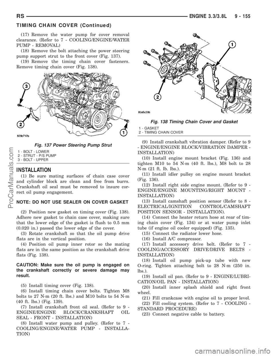
(18) Remove the bolt attaching the power steering
pump support strut to the front cover (Fig. 137).
(19) Remove the timing chain cover fasteners.
Remove timing chain cover (Fig. 138).
INSTALLATION
(1) Be sure mating surfaces of chain case cover
and cylinder block are clean and free from burrs.
Crankshaft oil seal must be removed to insure cor-
rect oil pump engagement.
NOTE: DO NOT USE SEALER ON COVER GASKET
(2) Position new gasket on timing cover (Fig. 138).
Adhere new gasket to chain case cover, making sure
that the lower edge of the gasket is flush to 0.5 mm
(0.020 in.) passed the lower edge of the cover.
(3) Rotate crankshaft so that the oil pump drive
flats are in the vertical position.
(4) Position oil pump inner rotor so the mating
flats are in the same position as the crankshaft drive
flats (Fig. 138).
CAUTION: Make sure the oil pump is engaged on
the crankshaft correctly or severe damage may
result.
(5) Install timing cover (Fig. 138).
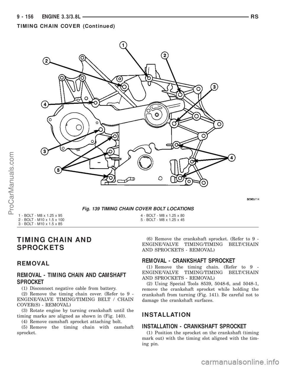
(6) Install timing chain cover bolts. Tighten M8
bolts to 27 N´m (20 ft. lbs.) and M10 bolts to 54 N´m
(40 ft. lbs.) (Fig. 139).
(7) Install crankshaft front oil seal. (Refer to 9 -
ENGINE/ENGINE BLOCK/CRANKSHAFT OIL
SEAL - FRONT - INSTALLATION)
(8) Install water pump and pulley. (Refer to 7 -
COOLING/ENGINE/WATER PUMP - INSTALLA-
TION)(9) Install crankshaft vibration damper. (Refer to 9
- ENGINE/ENGINE BLOCK/VIBRATION DAMPER -
INSTALLATION)
(10) Install engine mount bracket (Fig. 136) and
tighten M10 to 54 N´m (40 ft. lbs.), M8 bolt to 28
N´m (21 ft. lb. lbs.).
(11) Install idler pulley on engine mount bracket
(Fig. 136).
(12) Install right side engine mount. (Refer to 9 -
ENGINE/ENGINE MOUNTING/RIGHT MOUNT -
INSTALLATION)
(13) Install camshaft position sensor (Refer to 8 -
ELECTRICAL/IGNITION CONTROL/CAMSHAFT
POSITION SENSOR - INSTALLATION).
(14) Connect the heater return hose at rear of tim-
ing chain cover (Fig. 134) or at water pump inlet
tube (if engine oil cooler equipped) (Fig. 135).
(15) Connect the radiator lower hose.
(16) Install A/C compressor.
(17) Install accessory drive belt. (Refer to 7 -
COOLING/ACCESSORY DRIVE/DRIVE BELTS -
INSTALLATION)
(18) Install oil pump pick-up tube with new
O-ring. Tighten attaching bolt to 28 N´m (250 in.
lbs.).
(19) Install oil pan. (Refer to 9 - ENGINE/LUBRI-
CATION/OIL PAN - INSTALLATION)
(20) Install inner splash shield and right front
wheel.
(21) Fill crankcase with engine oil to proper level.
(22) Fill cooling system. (Refer to 7 - COOLING -
STANDARD PROCEDURE)
(23) Connect negative cable to battery.
Fig. 137 Power Steering Pump Strut
1 - BOLT - LOWER
2 - STRUT - P/S PUMP
3 - BOLT - UPPER
Fig. 138 Timing Chain Cover and Gasket
1 - GASKET
2 - TIMING CHAIN COVER
RSENGINE 3.3/3.8L9 - 155
TIMING CHAIN COVER (Continued)
ProCarManuals.com
Page 1335 of 2177
TIMING CHAIN AND
SPROCKETS
REMOVAL
REMOVAL - TIMING CHAIN AND CAMSHAFT
SPROCKET
(1) Disconnect negative cable from battery.
(2) Remove the timing chain cover. (Refer to 9 -
ENGINE/VALVE TIMING/TIMING BELT / CHAIN
COVER(S) - REMOVAL)
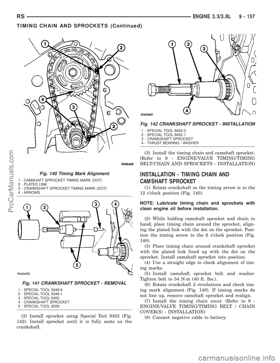
(3) Rotate engine by turning crankshaft until the
timing marks are aligned as shown in (Fig. 140).
(4) Remove camshaft sprocket attaching bolt.
(5) Remove the timing chain with camshaft
sprocket.(6) Remove the crankshaft sprocket. (Refer to 9 -
ENGINE/VALVE TIMING/TIMING BELT/CHAIN
AND SPROCKETS - REMOVAL)
REMOVAL - CRANKSHAFT SPROCKET
(1) Remove the timing chain. (Refer to 9 -
ENGINE/VALVE TIMING/TIMING BELT/CHAIN
AND SPROCKETS - REMOVAL)
(2) Using Special Tools 8539, 5048-6, and 5048-1,
remove the crankshaft sprocket while holding the
crankshaft from turning (Fig. 141). Be careful not to
damage the crankshaft surfaces.
INSTALLATION
INSTALLATION - CRANKSHAFT SPROCKET
(1) Position the sprocket on the crankshaft (timing
mark out) with the timing slot aligned with the tim-
ing pin.
Fig. 139 TIMING CHAIN COVER BOLT LOCATIONS
1 - BOLT - M8 x 1.25 x 95 4 - BOLT - M8 x 1.25 x 80
2 - BOLT - M10 x 1.5 x 100 5 - BOLT - M8 x 1.25 x 45
3 - BOLT - M10 x 1.5 x 85
9 - 156 ENGINE 3.3/3.8LRS
TIMING CHAIN COVER (Continued)
ProCarManuals.com
Page 1336 of 2177
(2) Install sprocket using Special Tool 8452 (Fig.
142). Install sprocket until it is fully seats on the
crankshaft.(3) Install the timing chain and camshaft sprocket.
(Refer to 9 - ENGINE/VALVE TIMING/TIMING
BELT/CHAIN AND SPROCKETS - INSTALLATION)
INSTALLATION - TIMING CHAIN AND
CAMSHAFT SPROCKET
(1) Rotate crankshaft so the timing arrow is to the
12 o'clock position (Fig. 140).
NOTE: Lubricate timing chain and sprockets with
clean engine oil before installation.
(2) While holding camshaft sprocket and chain in
hand, place timing chain around the sprocket, align-
ing the plated link with the dot on the sprocket. Posi-
tion the timing arrow to the 6 o'clock position (Fig.
140).
(3) Place timing chain around crankshaft sprocket
with the plated link lined up with the dot on the
sprocket. Install camshaft sprocket into position.
(4) Use a straight edge to check alignment of tim-
ing marks.
(5) Install camshaft sprocket bolt and washer.
Tighten bolt to 54 N´m (40 ft. lbs.).
(6) Rotate crankshaft 2 revolutions and check tim-
ing mark alignment (Fig. 140). If timing marks do
not line up, remove camshaft sprocket and realign.
(7) Install the timing chain cover. (Refer to 9 -
ENGINE/VALVE TIMING/TIMING BELT / CHAIN
COVER(S) - INSTALLATION)
(8) Connect negative cable to battery.
Fig. 140 Timing Mark Alignment
1 - CAMSHAFT SPROCKET TIMING MARK (DOT)
2 - PLATED LINK
3 - CRANKSHAFT SPROCKET TIMING MARK (DOT)
4 - ARROWS
Fig. 141 CRANKSHAFT SPROCKET - REMOVAL
1 - SPECIAL TOOL 5048-6
2 - SPECIAL TOOL 5048-1
3 - SPECIAL TOOL 8450
4 - CRANKSHAFT SPROCKET
5 - SPECIAL TOOL 8539
Fig. 142 CRANKSHAFT SPROCKET - INSTALLATION
1 - SPECIAL TOOL 8452-3
2 - SPECIAL TOOL 8452-1
3 - CRANKSHAFT SPROCKET
4 - THRUST BEARING / WASHER
RSENGINE 3.3/3.8L9 - 157
TIMING CHAIN AND SPROCKETS (Continued)
ProCarManuals.com
Page 1383 of 2177
INSTALLATION
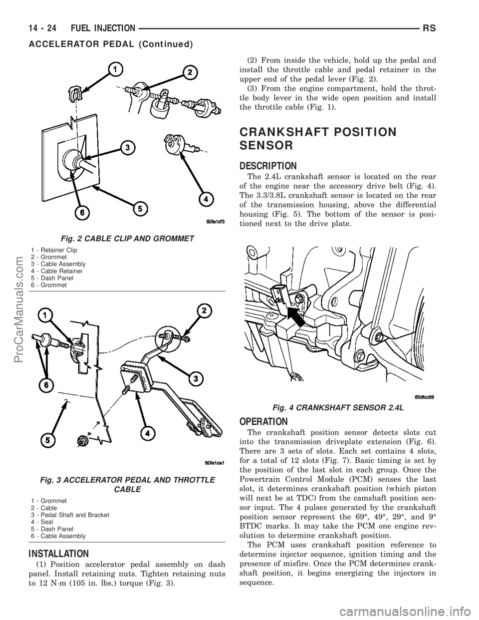
(1) Position accelerator pedal assembly on dash
panel. Install retaining nuts. Tighten retaining nuts
to 12 N´m (105 in. lbs.) torque (Fig. 3).(2) From inside the vehicle, hold up the pedal and
install the throttle cable and pedal retainer in the
upper end of the pedal lever (Fig. 2).
(3) From the engine compartment, hold the throt-
tle body lever in the wide open position and install
the throttle cable (Fig. 1).
CRANKSHAFT POSITION
SENSOR
DESCRIPTION
The 2.4L crankshaft sensor is located on the rear
of the engine near the accessory drive belt (Fig. 4).
The 3.3/3.8L crankshaft sensor is located on the rear
of the transmission housing, above the differential
housing (Fig. 5). The bottom of the sensor is posi-
tioned next to the drive plate.
OPERATION
The crankshaft position sensor detects slots cut
into the transmission driveplate extension (Fig. 6).
There are 3 sets of slots. Each set contains 4 slots,
for a total of 12 slots (Fig. 7). Basic timing is set by
the position of the last slot in each group. Once the
Powertrain Control Module (PCM) senses the last
slot, it determines crankshaft position (which piston
will next be at TDC) from the camshaft position sen-
sor input. The 4 pulses generated by the crankshaft
position sensor represent the 69É, 49É, 29É, and 9É
BTDC marks. It may take the PCM one engine rev-
olution to determine crankshaft position.
The PCM uses crankshaft position reference to
determine injector sequence, ignition timing and the
presence of misfire. Once the PCM determines crank-
shaft position, it begins energizing the injectors in
sequence.
Fig. 2 CABLE CLIP AND GROMMET
1 - Retainer Clip
2 - Grommet
3 - Cable Assembly
4 - Cable Retainer
5 - Dash Panel
6 - Grommet
Fig. 3 ACCELERATOR PEDAL AND THROTTLE
CABLE
1 - Grommet
2 - Cable
3 - Pedal Shaft and Bracket
4 - Seal
5 - Dash Panel
6 - Cable Assembly
Fig. 4 CRANKSHAFT SENSOR 2.4L
14 - 24 FUEL INJECTIONRS
ACCELERATOR PEDAL (Continued)
ProCarManuals.com
Page 1435 of 2177
(17) Remove the 3 bolts attaching the front
bracket to the power steering pump and separate the
power steering pump from the front bracket.
(18) If the power steering pump pulley needs to be
transferred, (Refer to 19 - STEERING/PUMP - DIS-
ASSEMBLY).
REMOVAL - PUMP (3.3L/3.8L ENGINE)
(1) Remove the (-) negative battery cable from the
battery and isolate cable.
(2) Remove the wiper module (unit)(Refer to 8 -
ELECTRICAL/WIPERS/WASHERS/WIPER MOD-
ULE - REMOVAL).
(3) Raise the vehicle. (Refer to LUBRICATION &
MAINTENANCE/HOISTING - STANDARD PROCE-
DURE)
(4) Remove the drive belt splash shield.
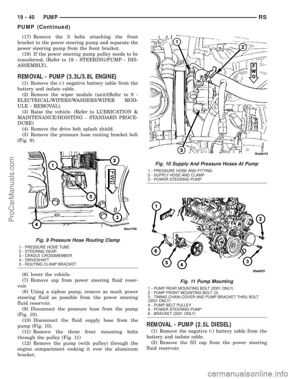
(5) Remove the pressure hose routing bracket bolt
(Fig. 9).
(6) lower the vehicle.
(7) Remove cap from power steering fluid reser-
voir.
(8) Using a siphon pump, remove as much power
steering fluid as possible from the power steering
fluid reservoir.
(9) Disconnect the pressure hose from the pump
(Fig. 10).
(10) Disconnect the fluid supply hose from the
pump (Fig. 10).
(11) Remove the three front mounting bolts
through the pulley (Fig. 11)
(12) Remove the pump (with pulley) through the
engine compartment rocking it over the aluminum
bracket.
REMOVAL - PUMP (2.5L DIESEL)
(1) Remove the negative (-) battery cable from the
battery and isolate cable.
(2) Remove the fill cap from the power steering
fluid reservoir.
Fig. 9 Pressure Hose Routing Clamp
1 - PRESSURE HOSE TUBE
2 - STEERING GEAR
3 - CRADLE CROSSMEMBER
4 - DRIVESHAFT
5 - ROUTING CLAMP BRACKET
Fig. 10 Supply And Pressure Hoses At Pump
1 - PRESSURE HOSE AND FITTING
2 - SUPPLY HOSE AND CLAMP
3 - POWER STEERING PUMP
Fig. 11 Pump Mounting
1 - PUMP REAR MOUNTING BOLT (2001 ONLY)
2 - PUMP FRONT MOUNTING BOLT (3)
3 - TIMING CHAIN COVER AND PUMP BRACKET THRU BOLT
(2001 ONLY)
4 - PUMP BELT PULLEY
5 - POWER STEERING PUMP
6 - BRACKET (2001 ONLY)
19 - 40 PUMPRS
PUMP (Continued)
ProCarManuals.com
Page 1849 of 2177
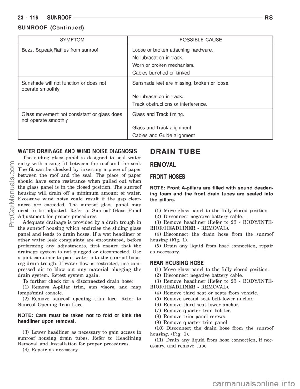
SYMPTOM POSSIBLE CAUSE
Buzz, Squeak,Rattles from sunroof Loose or broken attaching hardware.
No lubracation in track.
Worn or broken mechanism.
Cables bunched or kinked
Sunshade will not function or does not
operate smoothlySunshade feet are missing, broken or loose.
No lubracation in track.
Track obstructions or interference.
Glass movement not consistant or glass does
not operate smoothlyGlass and Track timing.
Glass and Track alignment
Cables and Guide alignment
WATER DRAINAGE AND WIND NOISE DIAGNOSIS
The sliding glass panel is designed to seal water
entry with a snug fit between the roof and the seal.
The fit can be checked by inserting a piece of paper
between the roof and the seal. The piece of paper
should have some resistance when pulled out when
the glass panel is in the closed position. The sunroof
housing will drain off a minimum amount of water.
Excessive wind noise could result if the gap clear-
ances are exceeded. The sunroof glass panel may
need to be adjusted. Refer to Sunroof Glass Panel
Adjustment for proper procedures.
Adequate drainage is provided by a drain trough in
the sunroof housing which encircles the sliding glass
panel and leads to drain hoses. If a wet headliner or
other water leak complaints are encountered, before
performing any adjustments, first ensure that the
drainage system is not plugged or disconnected. Use
a pint container to pour water into the sunroof hous-
ing drain trough. If water flow is restricted, use com-
pressed air to blow out any material plugging the
drain system. Retest system again.
To further check for a disconnected drain hose:
(1) Remove A-pillar trim, sun visors, and map
lamps/mini console.
(2) Remove sunroof opening trim lace. Refer to
Sunroof Opening Trim Lace.
NOTE: Care must be taken not to fold or kink the
headliner upon removal.
(3) Lower headliner as necessary to gain access to
sunroof housing drain tubes. Refer to Headlining
Removal and Installation for proper procedures.
(4) Repair as necessary.
DRAIN TUBE
REMOVAL
FRONT HOSES
NOTE: Front A-pillars are filled with sound deaden-
ing foam and the front drain tubes are sealed into
the pillars.
(1) Move glass panel to the fully closed position.
(2) Disconnect negative battery cable.
(3) Remove headliner (Refer to 23 - BODY/INTE-
RIOR/HEADLINER - REMOVAL).
(4) Disconnect the drain hose from the sunroof
housing (Fig. 1).
(5) Drain any liquid from hose connection, repair
as necessary.
REAR HOUSING HOSE
(1) Move glass panel to the fully closed position.
(2) Disconnect negative battery cable.
(3) Remove headliner (Refer to 23 - BODY/INTE-
RIOR/HEADLINER - REMOVAL).
(4) Remove third seat or seats from vehicle.
(5) Remove second seat belt lower anchor.
(6) Remove third seat lower anchor.
(7) Remove quarter trim bolster.
(8) Remove trim panel screws.
(9) Remove quarter trim panel
(10) Disconnect the drain hose from the sunroof
housing. (Fig. 1).
(11) Drain any liquid from hose connection, if nec-
essary, and remove tube.
23 - 116 SUNROOFRS
SUNROOF (Continued)
ProCarManuals.com
Page 2142 of 2177
BELT - DIAGNOSIS AND TESTING,
ACCESSORY DRIVE.....................7-7
BELT - INSTALLATION, TIMING...........9-65
BELT - REMOVAL, TIMING..............9-63
BELT & RETRACTOR - FIRST ROW -
OUTBOARD - INSTALLATION, SEAT......8O-13
BELT & RETRACTOR - FIRST ROW -
OUTBOARD - REMOVAL, SEAT..........8O-13
BELT & RETRACTOR - OUTBOARD -
FRONT - INSTALLATION, SEAT..........8O-13
BELT & RETRACTOR - OUTBOARD -
FRONT - REMOVAL, SEAT..............8O-13
BELT & RETRACTOR - SECOND ROW -
LEFT OUTBOARD - INSTALLATION,
SEAT ..............................8O-16
BELT & RETRACTOR - SECOND ROW -
LEFT OUTBOARD - REMOVAL, SEAT.....8O-16
BELT & RETRACTOR - SECOND ROW -
RIGHT OUTBOARD - INSTALLATION,
SEAT ..............................8O-14
BELT & RETRACTOR - SECOND ROW -
RIGHT OUTBOARD - REMOVAL, SEAT....8O-14
BELT & RETRACTOR - SECOND ROW -
RIGHT OUTBOARD WITH REAR HVAC -
LWB - INSTALLATION, SEAT............8O-15
BELT & RETRACTOR - SECOND ROW -
RIGHT OUTBOARD WITH REAR HVAC -
LWB - REMOVAL, SEAT...............8O-15
BELT BUCKLE - FIRST ROW - BENCH -
INSTALLATION, SEAT.................8O-12
BELT BUCKLE - FIRST ROW - BENCH -
REMOVAL, SEAT.....................8O-12
BELT BUCKLE - FIRST ROW INBOARD -
QUAD BUCKET - INSTALLATION, SEAT....8O-11
BELT BUCKLE - FIRST ROW INBOARD -
QUAD BUCKET - REMOVAL, SEAT.......8O-11
BELT BUCKLE - FRONT INBOARD -
INSTALLATION, SEAT.................8O-11
BELT BUCKLE - FRONT INBOARD -
REMOVAL, SEAT.....................8O-11
BELT BUCKLE - SECOND ROW - THREE
PASSENGER BENCH - INSTALLATION,
SEAT ..............................8O-14
BELT BUCKLE - SECOND ROW - THREE
PASSENGER BENCH - REMOVAL, SEAT . . . 8O-14
BELT BUCKLE - SECOND ROW INBOARD
- 50/50 BENCH - INSTALLATION, SEAT . . . 8O-12
BELT BUCKLE - SECOND ROW INBOARD
- 50/50 BENCH - REMOVAL, SEAT.......8O-12
BELT COVER(S) - INSTALLATION,
TIMING.............................9-62
BELT COVER(S) - REMOVAL, TIMING......9-61
BELT HEIGHT ADJUSTER-BOR
C-PILLAR - INSTALLATION, SEAT........8O-12
BELT HEIGHT ADJUSTER-BOR
C-PILLAR - REMOVAL, SEAT...........8O-12
BELT HEIGHT ADJUSTER KNOB -
INSTALLATION, SEAT.................8O-13
BELT HEIGHT ADJUSTER KNOB -
REMOVAL, SEAT.....................8O-13
BELT MOLDING - INSTALLATION, FRONT
DOOR INNER.......................23-112
BELT MOLDING - INSTALLATION, FRONT
DOOR OUTER......................23-110
BELT MOLDING - REMOVAL, FRONT
DOOR INNER.......................23-112
BELT MOLDING - REMOVAL, FRONT
DOOR OUTER......................23-110
BELT TENSION - STANDARD
PROCEDURE, CHECKING POWER
STEERING............................7-8
BELT TENSION, SPECIFICATIONS -
ACCESSORY DRIVE.....................7-5
BELT TENSIONER - 2.4L - INSTALLATION . . 7-10
BELT TENSIONER - 2.4L - REMOVAL......7-10
BELT TENSIONER - 3.3/3.8L -
INSTALLATION........................7-12
BELT TENSIONER - 3.3/3.8L - REMOVAL . . . 7-12
BELT TENSIONER - DESCRIPTION, SEAT . . 8O-16
BELT TENSIONER - OPERATION, SEAT....8O-16
BELT TENSIONER & PULLEY -
INSTALLATION, TIMING.................9-69
BELT TENSIONER & PULLEY -
REMOVAL, TIMING
....................9-68
BELTS - 2.4L - ADJUSTMENTS, DRIVE
.....7-10
BELTS - 2.4L - CLEANING, DRIVE
..........7-9
BELTS - 2.4L - INSPECTION, DRIVE
........7-9
BELTS - 2.4L - INSTALLATION, DRIVE
.....7-10BELTS - 2.4L - REMOVAL, DRIVE..........7-8
BELTS - 3.3/3.8L - CLEANING, DRIVE......7-11
BELTS - 3.3/3.8L - INSPECTION, DRIVE....7-11
BELTS - 3.3/3.8L - INSTALLATION, DRIVE . . 7-12
BELTS - 3.3/3.8L - REMOVAL, DRIVE......7-11
BENCH - INSTALLATION, SEAT BACK
HINGE COVERS - QUAD BUCKET, 50/50
SPLIT.............................23-100
BENCH - INSTALLATION, SEAT BELT
BUCKLE - FIRST ROW................8O-12
BENCH - INSTALLATION, SEAT BELT
BUCKLE - SECOND ROW - THREE
PASSENGER........................8O-14
BENCH - INSTALLATION, SEAT BELT
BUCKLE - SECOND ROW INBOARD -
50/50..............................8O-12
BENCH - INSTALLATION, SEAT CUSHION
COVER - QUAD BUCKET, 50/50 SPLIT....23-99
BENCH - REMOVAL, SEAT BACK HINGE
COVERS - QUAD BUCKET, 50/50 SPLIT . . 23-100
BENCH - REMOVAL, SEAT BELT BUCKLE
- FIRST ROW.......................8O-12
BENCH - REMOVAL, SEAT BELT BUCKLE
- SECOND ROW - THREE PASSENGER....8O-14
BENCH - REMOVAL, SEAT BELT BUCKLE
- SECOND ROW INBOARD - 50/50.......8O-12
BENCH - REMOVAL, SEAT CUSHION
COVER - QUAD BUCKET, 50/50 SPLIT....23-98
BENCH SEAT - REMOVAL, CHILD SEAT
MODULE...........................23-86
BENCH SEAT BACK - INSTALLATION.....23-101
BENCH SEAT BACK - REMOVAL........23-101
BENCH SEAT BACK COVER -
INSTALLATION......................23-102
BENCH SEAT BACK COVER - REMOVAL . . 23-102
BENCH SEAT BACK HINGE - REMOVAL . . 23-100
BENCH SEAT RISER - 50/50 SPLIT -
INSTALLATION.......................23-99
BENCH SEAT RISER - 50/50 SPLIT -
REMOVAL..........................23-99
BENCH SEAT RISER - SECOND ROW -
INSTALLATION......................23-100
BENCH SEAT RISER - SECOND ROW -
REMOVAL..........................23-99
BENCH SEAT RISER - THIRD ROW -
INSTALLATION......................23-100
BENCH SEAT RISER - THIRD ROW -
REMOVAL.........................23-100
BENCH SEAT TRACK - INSTALLATION . . . 23-102
BENCH SEAT TRACK - REMOVAL.......23-102
BENCH SEATBACK PANEL -
INSTALLATION.......................23-98
BENCH SEATBACK PANEL - REMOVAL....23-98
BEZEL - INSTALLATION, CLUSTER.......23-62
BEZEL - INSTALLATION, INSTRUMENT
PANEL CENTER......................23-67
BEZEL - INSTALLATION, SLIDING DOOR
STOP BUMPER......................23-25
BEZEL - REMOVAL, CLUSTER...........23-62
BEZEL - REMOVAL, INSTRUMENT PANEL
CENTER............................23-67
BEZEL - REMOVAL, SLIDING DOOR
STOP BUMPER......................23-25
BEZEL OUTLETS - INSTALLATION,
CENTER............................24-42
BEZEL OUTLETS - REMOVAL, CENTER....24-40
BI-DIRECTIONAL OVERRUNNING
CLUTCH - DESCRIPTION................3-34
BI-DIRECTIONAL OVERRUNNING
CLUTCH - OPERATION.................3-36
BIN - INSTALLATION, UNDER SEAT
STORAGE..........................23-103
BIN - REMOVAL, UNDER SEAT STORAGE . 23-103
BIN GUIDE - INSTALLATION, UNDER
SEAT STORAGE.....................23-104
BIN GUIDE - REMOVAL, UNDER SEAT
STORAGE..........................23-104
BIN LOCK/LATCH - INSTALLATION,
UNDER SEAT STORAGE...............23-104
BIN LOCK/LATCH - REMOVAL, UNDER
SEAT STORAGE.....................23-104
BLADES - CLEANING, WIPER
...........8R-17
BLADES - INSTALLATION, WIPER
........8R-17
BLADES - REMOVAL, WIPER
...........8R-17
BLEEDING - STANDARD PROCEDURE,
ANTILOCK BRAKE SYSTEM
..............5-78
BLEEDING - STANDARD PROCEDURE,
BASE BRAKE
..........................5-7BLEEDING - STANDARD PROCEDURE,
MASTER CYLINDER...................5-35
BLEND DOOR ACTUATOR -
DESCRIPTION..................24-11,24-30
BLEND DOOR ACTUATOR -
INSTALLATION..................24-12,24-31
BLEND DOOR ACTUATOR - OPERATION . . 24-11,
24-30
BLEND DOOR ACTUATOR - REMOVAL....24-12,
24-31
BLOCK - CLEANING, ENGINE.......9-112,9-36
BLOCK - DESCRIPTION, ENGINE.....9-112,9-35
BLOCK - DESCRIPTION, NON-ABS
JUNCTION...........................5-33
BLOCK - INSPECTION, ENGINE......9-112,9-36
BLOCK - INSTALLATION, NON-ABS
JUNCTION...........................5-33
BLOCK - OPERATION, NON-ABS
JUNCTION...........................5-33
BLOCK - REMOVAL, NON-ABS JUNCTION . . 5-33
BLOCK HEATER - DESCRIPTION, ENGINE . . . 7-20
BLOCK HEATER - INSTALLATION,
ENGINE.............................7-20
BLOCK HEATER - OPERATION, ENGINE....7-20
BLOCK HEATER - REMOVAL, ENGINE......7-20
BLOCK HEATER TESTING - DIAGNOSIS
AND TESTING, ENGINE.................7-20
BLOCKER LATCH - INSTALLATION, FUEL
FILL DOOR.........................23-52
BLOCKER LATCH - REMOVAL, FUEL FILL
DOOR.............................23-52
BLOCKER LATCH STRIKER -
INSTALLATION, FUEL FILL DOOR........23-52
BLOCKER LATCH STRIKER - REMOVAL,
FUEL FILL DOOR.....................23-52
BLOCKER LOCKOUT LINK -
INSTALLATION, FUEL FILL DOOR........23-53
BLOCKER LOCKOUT LINK - REMOVAL,
FUEL FILL DOOR.....................23-52
BLOWER MOTOR - DESCRIPTION . . 24-43,24-53
BLOWER MOTOR - DIAGNOSIS AND
TESTING......................24-43,24-54
BLOWER MOTOR - INSTALLATION . . 24-46,24-56
BLOWER MOTOR - OPERATION....24-43,24-54
BLOWER MOTOR - REMOVAL......24-46,24-56
BLOWER MOTOR RELAY - DESCRIPTION . 24-13,
24-32
BLOWER MOTOR RELAY - DIAGNOSIS
AND TESTING..................24-14,24-33
BLOWER MOTOR RELAY -
INSTALLATION..................24-14,24-33
BLOWER MOTOR RELAY - OPERATION . . . 24-13,
24-32
BLOWER MOTOR RELAY - REMOVAL....24-14,
24-33
BLOWER MOTOR RESISTOR -
DESCRIPTION..................24-14,24-34
BLOWER MOTOR RESISTOR -
DIAGNOSIS AND TESTING........24-15,24-34
BLOWER MOTOR RESISTOR -
INSTALLATION..................24-16,24-35
BLOWER MOTOR RESISTOR -
OPERATION....................24-15,24-34
BLOWER MOTOR RESISTOR - REMOVAL . 24-16,
24-35
BODY - ASSEMBLY, VALVE............21-257
BODY - DESCRIPTION, THROTTLE.......14-34
BODY - DESCRIPTION, VALVE..........21-250
BODY - DISASSEMBLY, VALVE.........21-252
BODY - INSTALLATION, THROTTLE.......14-35
BODY - INSTALLATION, VALVE.........21-262
BODY - OPERATION, THROTTLE.........14-34
BODY - OPERATION, VALVE...........21-250
BODY - REMOVAL, THROTTLE..........14-35
BODY - REMOVAL, VALVE.............21-251
BODY AND CABLE - DESCRIPTION,
ANTENNA...........................8A-4
BODY AND CABLE - DIAGNOSIS AND
TESTING, ANTENNA...................8A-4
BODY AND CABLE - INSTALLATION,
ANTENNA
...........................8A-6
BODY AND CABLE - OPERATION,
ANTENNA
...........................8A-4
BODY AND CABLE - REMOVAL,
ANTENNA
...........................8A-5
BODY CODE PLATE - DESCRIPTION
.....Intro.-1
BODY CONTROL MODULE -
DESCRIPTION
........................8E-3
RSINDEX3
Description Group-Page Description Group-Page Description Group-Page
ProCarManuals.com