2003 CHRYSLER CARAVAN roof
[x] Cancel search: roofPage 1848 of 2177

SUNROOF DIAGNOSIS CHART
SYMPTOM POSSIBLE CAUSE
Sunroof motor inoperative. Faulty control switch.
Faulty circuit ground between sunroof module, control switch,
and body harness.
Faulty power circuit between sunroof module, control switch,
and body harness.
Faulty sunroof drive motor.
Faulty sunroof module.
Audible whine when switch is depressed,
sunroof does not operate.Faulty sunroof drive motor.
Binding cable.
Audible clicking or ratcheting when switch is
pressed, sunroof does not operate.Broken or worn drive cable.
Worn drive motor gear.
Mechanisms not synchronized.
Sunroof vents and opens, but does not close. Broken or disengaged trough guide
Binding cable.
Faulty circuit.
Faulty control switch.
Faulty sunroof module.
Faulty drive motor.
Sunroof vents, but does not open. Binding cable or mechanism.
Faulty circuit.
Faulty switch.
Faulty sunroof module.
Sunroof does not vent Binding cable or mechanism.
Faulty circuit.
Faulty control switch.
Faulty sunroof module.
Sunroof water leak. Drain tubes clogged or kinked or disconnected from the
sunroof.
Glass panel improperly adjusted.
Faulty glass panel seal.
Gurgling sound from sunroof Low spot in drain hose routing, allowing water to stand.
Wind noise from sunroof. Glass panel compression to the roof opening not consistant.
Wind deflector not deploying properly.
Glass not installed or adjusted properly.
Faulty glass panel seal.
RSSUNROOF23 - 115
SUNROOF (Continued)
ProCarManuals.com
Page 1849 of 2177
SYMPTOM POSSIBLE CAUSE
Buzz, Squeak,Rattles from sunroof Loose or broken attaching hardware.
No lubracation in track.
Worn or broken mechanism.
Cables bunched or kinked
Sunshade will not function or does not
operate smoothlySunshade feet are missing, broken or loose.
No lubracation in track.
Track obstructions or interference.
Glass movement not consistant or glass does
not operate smoothlyGlass and Track timing.
Glass and Track alignment
Cables and Guide alignment
WATER DRAINAGE AND WIND NOISE DIAGNOSIS
The sliding glass panel is designed to seal water
entry with a snug fit between the roof and the seal.
The fit can be checked by inserting a piece of paper
between the roof and the seal. The piece of paper
should have some resistance when pulled out when
the glass panel is in the closed position. The sunroof
housing will drain off a minimum amount of water.
Excessive wind noise could result if the gap clear-
ances are exceeded. The sunroof glass panel may
need to be adjusted. Refer to Sunroof Glass Panel
Adjustment for proper procedures.
Adequate drainage is provided by a drain trough in
the sunroof housing which encircles the sliding glass
panel and leads to drain hoses. If a wet headliner or
other water leak complaints are encountered, before
performing any adjustments, first ensure that the
drainage system is not plugged or disconnected. Use
a pint container to pour water into the sunroof hous-
ing drain trough. If water flow is restricted, use com-
pressed air to blow out any material plugging the
drain system. Retest system again.
To further check for a disconnected drain hose:
(1) Remove A-pillar trim, sun visors, and map
lamps/mini console.
(2) Remove sunroof opening trim lace. Refer to
Sunroof Opening Trim Lace.
NOTE: Care must be taken not to fold or kink the
headliner upon removal.
(3) Lower headliner as necessary to gain access to
sunroof housing drain tubes. Refer to Headlining
Removal and Installation for proper procedures.
(4) Repair as necessary.
DRAIN TUBE
REMOVAL
FRONT HOSES
NOTE: Front A-pillars are filled with sound deaden-
ing foam and the front drain tubes are sealed into
the pillars.
(1) Move glass panel to the fully closed position.
(2) Disconnect negative battery cable.
(3) Remove headliner (Refer to 23 - BODY/INTE-
RIOR/HEADLINER - REMOVAL).
(4) Disconnect the drain hose from the sunroof
housing (Fig. 1).
(5) Drain any liquid from hose connection, repair
as necessary.
REAR HOUSING HOSE
(1) Move glass panel to the fully closed position.
(2) Disconnect negative battery cable.
(3) Remove headliner (Refer to 23 - BODY/INTE-
RIOR/HEADLINER - REMOVAL).
(4) Remove third seat or seats from vehicle.
(5) Remove second seat belt lower anchor.
(6) Remove third seat lower anchor.
(7) Remove quarter trim bolster.
(8) Remove trim panel screws.
(9) Remove quarter trim panel
(10) Disconnect the drain hose from the sunroof
housing. (Fig. 1).
(11) Drain any liquid from hose connection, if nec-
essary, and remove tube.
23 - 116 SUNROOFRS
SUNROOF (Continued)
ProCarManuals.com
Page 1850 of 2177
INSTALLATION
FRONT HOSES
(1) Connect the new drain hose to the sunroof
housing and test drainage (Fig. 1).
(2) Install headliner (Refer to 23 - BODY/INTERI-
OR/HEADLINER - INSTALLATION).
(3) Install sunroof opening trim lace.
(4) Connect the control switch wire connector and
install control switch.
(5) Verify sunroof operation and alignment.
REAR HOUSING HOSE
(1) Connect the new drain hose to the sunroof
housing and test drainage (Fig. 1).
(2) Install headliner(Refer to 23 - BODY/INTERI-
OR/HEADLINER - INSTALLATION).
(3) Install sunroof opening trim lace.
(4) Connect the control switch wire connector and
install control switch.
(5) Verify sunroof operation and alignment.
GLASS PANEL
REMOVAL
(1) Move the glass panel to the vent position.
(2) Slide sunshade rearward to the open position.
(3) Remove the glass panel screws (Fig. 1).
(4) Lift off glass panel and remove from vehicle.
INSTALLATION
(1) Position glass panel on to mechanism lift arms.
(2) Start the attaching screws, and hand tighten
(Fig. 1).
(3) Adjust sunroof glass to fit flush with roof
line(Refer to 23 - BODY/SUNROOF/GLASS PANEL -
ADJUSTMENTS).
(4) Verify sunroof operation and alignment.
ADJUSTMENTS
SUNROOF GLASS PANEL ADJUSTMENT
(1) Move the sunshade rearward to the open posi-
tion.
(2) Move the sunroof glass panel to the fully closed
position.
(3) Loosen the forward attaching screws on each
side enough to make the front of the glass to adjust
up or down.
(4) Adjust the front surface of the sunroof glass
panel 0.00 mm to 1.75 mm (0.00 in. to 0.07 in.) below
the top surface of the roof.
(5) Tighten the front glass panel attaching screws
to 3.5 N´m (31 in. lbs.) torque (Fig. 1).(6) Loosen the rear screws on each side enough to
make the rear adjustment (Fig. 1).
(7) Adjust the rear surface of the sunroof glass
panel 0.00 mm to 1.75 mm (0.03 in. to 0.07 in.) above
the top surface of the roof.
(8) Tighten the rear glass panel attaching screws
to 3.5 N´m (31 in. lbs.) torque (Fig. 1).
(9) Check for proper fit. If not OK, repeat glass
panel adjustment.
SUNROOF ASSEMBLY
REMOVAL
(1) Move glass panel to the fully closed position.
(2) Disconnect battery negative cable.
(3) Remove headliner (Refer to 23 - BODY/INTE-
RIOR/HEADLINER - REMOVAL).
(4) Disconnect the four drain tubes from sunroof
housing (Fig. 1).
(5) Loosen fasteners attaching sunroof assembly
(Fig. 1).
(6) With the aid of a helper, support the sunroof
and remove the fasteners attaching sunroof assembly
to roof panel (Fig. 1).
(7) Remove sunroof from vehicle.
INSTALLATION
(1) Raise sunroof module assembly and guide it
carefully into position.
(2) While supporting the sunroof assembly tighten
the attaching screws (Fig. 1). Tighten to 6 N´m (53
in. lbs.) torque.
(3) Connect the drain tubes to the sunroof (Fig. 1).
(4) Connect battery negative cable.
(5) Test sunroof operation, adjust as necessary(Re-
fer to 23 - BODY/SUNROOF/GLASS PANEL -
ADJUSTMENTS).
(6) Install headliner (Refer to 23 - BODY/INTERI-
OR/HEADLINER - INSTALLATION).
(7) Install sunroof opening trim lace position(Refer
to 23 - BODY/SUNROOF/OPENING TRIM LACE -
INSTALLATION).
SUNSHADE
REMOVAL
(1) Place the sunroof glass panel in the vent posi-
tion.
(2) Remove glass panel (Refer to 23 - BODY/SUN-
ROOF/GLASS PANEL - REMOVAL).
(3) Remove water channel (Fig. 1).
(4) Cycle sunroof motor to the open position.
(5) Move sunshade towards the closed position
stopping three to four inches from the closed position.
RSSUNROOF23 - 117
DRAIN TUBE (Continued)
ProCarManuals.com
Page 1851 of 2177
(6) Depress the spring feet clips on one side of the
sun shade.
(7) Remove sunshade.
INSTALLATION
(1) Place one side of the sunshade spring feet clips
into the top track U-frame.
(2) Depress the both releasing clips on the other
side to allow them to go into the top track U-frame.
(3) Move sunshade to the open position.
(4) Install water channel (Fig. 1).
(5) Verify that the sunshade move back and forth
properly.
(6) Cycle sunroof towards the closed position.
(7) Install glass panel (Refer to 23 - BODY/SUN-
ROOF/GLASS PANEL - INSTALLATION).
WIND DEFLECTOR
REMOVAL
(1) Fully open sunroof glass panel.
(2) Disconnect negative battery cable.
(3) Remove sunroof assembly (Refer to 23 - BODY/
SUNROOF/MODULE ASSEMBLY - REMOVAL).
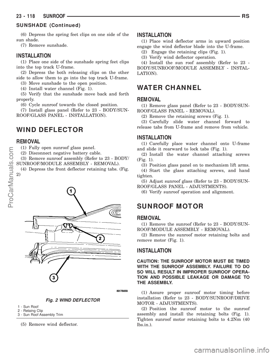
(4) Depress the front deflector retaining tabs. (Fig.
2)
(5) Remove wind deflector.
INSTALLATION
(1) Place wind deflector arms in upward position
engage the wind deflector blade into the U-frame.
(2) Engage the retaining clips (Fig. 1).
(3) Verify wind deflector operation.
(4) Install the sun roof assembly (Refer to 23 -
BODY/SUNROOF/MODULE ASSEMBLY - INSTAL-
LATION).
WATER CHANNEL
REMOVAL
(1) Remove glass panel (Refer to 23 - BODY/SUN-
ROOF/GLASS PANEL - REMOVAL).
(2) Remove the retaining screws (Fig. 1).
(3) Carefully slide water channel forward to
release tabs from U-frame and remove from vehicle.
INSTALLATION
(1) Carefully place water channel onto U-frame
and slide it rearward to lock tabs (Fig. 1).
(2) Install the water channel attaching screws
(Fig. 1).
(3) Position glass panel on to mechanism lift arms.
(4) Start the glass attaching screws, and hand
tighten.
(5) Adjust sunroof glass (Refer to 23 - BODY/SUN-
ROOF/GLASS PANEL - ADJUSTMENTS).
(6) Verify sunroof operation and alignment.
SUNROOF MOTOR
REMOVAL
(1) Remove the sunroof (Refer to 23 - BODY/SUN-
ROOF/MODULE ASSEMBLY - REMOVAL).
(2) Remove the sunroof motor retaining bolts and
remove motor (Fig. 1).
INSTALLATION
CAUTION: THE SUNROOF MOTOR MUST BE TIMED
WITH THE SUNROOF ASSEMBLY. FAILURE TO DO
SO WILL RESULT IN IMPROPER SUNROOF OPERA-
TION AND POSSIBLE LEAKAGE OR DAMAGE TO
THE ASSEMBLY.
(1) Assure proper sunroof motor timing before
installation (Refer to 23 - BODY/SUNROOF/DRIVE
MOTOR - ADJUSTMENTS).
(2) Position the sunroof motor to the sunroof
assembly and install the retaining bolts (Fig. 1).
Tighten sunroof motor retaining bolts to 4.2Nm (40
lbs.in.).
Fig. 2 WIND DEFLECTOR
1 - Sun Roof
2 - Retaing Clip
3 - Sun Roof Assembly Trim
23 - 118 SUNROOFRS
SUNSHADE (Continued)
ProCarManuals.com
Page 1852 of 2177
(3) Connect the timed sunroof assembly to a
power source and assure proper operation before
installing the sunroof assembly into the vehicle.
ADJUSTMENTS
ADJUSTMENT
CAUTION: THE IS NO ADJUSTMENT AVAILABLE
FOR A NORMALLY OPERATING SUNROOF. THIS
PROCEDURE IS USE TO SET SUNROOF MOTOR TO
SUNROOF ASSEMBLY TIMING.
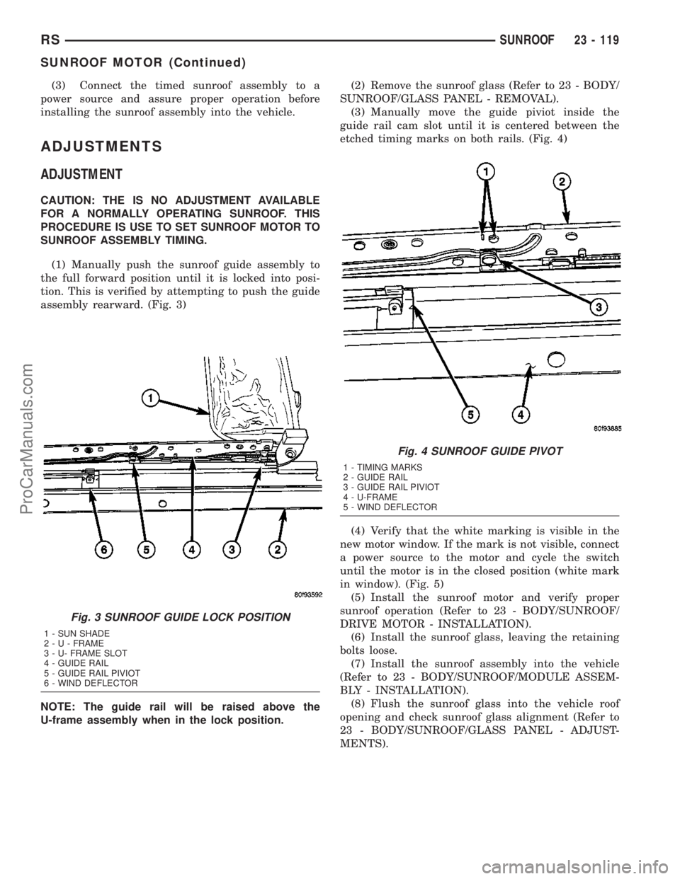
(1) Manually push the sunroof guide assembly to
the full forward position until it is locked into posi-
tion. This is verified by attempting to push the guide
assembly rearward. (Fig. 3)
NOTE: The guide rail will be raised above the
U-frame assembly when in the lock position.(2) Remove the sunroof glass (Refer to 23 - BODY/
SUNROOF/GLASS PANEL - REMOVAL).
(3) Manually move the guide piviot inside the
guide rail cam slot until it is centered between the
etched timing marks on both rails. (Fig. 4)
(4) Verify that the white marking is visible in the
new motor window. If the mark is not visible, connect
a power source to the motor and cycle the switch
until the motor is in the closed position (white mark
in window). (Fig. 5)
(5) Install the sunroof motor and verify proper
sunroof operation (Refer to 23 - BODY/SUNROOF/
DRIVE MOTOR - INSTALLATION).
(6) Install the sunroof glass, leaving the retaining
bolts loose.
(7) Install the sunroof assembly into the vehicle
(Refer to 23 - BODY/SUNROOF/MODULE ASSEM-
BLY - INSTALLATION).
(8) Flush the sunroof glass into the vehicle roof
opening and check sunroof glass alignment (Refer to
23 - BODY/SUNROOF/GLASS PANEL - ADJUST-
MENTS).
Fig. 3 SUNROOF GUIDE LOCK POSITION
1 - SUN SHADE
2-U-FRAME
3 - U- FRAME SLOT
4 - GUIDE RAIL
5 - GUIDE RAIL PIVIOT
6 - WIND DEFLECTOR
Fig. 4 SUNROOF GUIDE PIVOT
1 - TIMING MARKS
2 - GUIDE RAIL
3 - GUIDE RAIL PIVIOT
4 - U-FRAME
5 - WIND DEFLECTOR
RSSUNROOF23 - 119
SUNROOF MOTOR (Continued)
ProCarManuals.com
Page 1853 of 2177
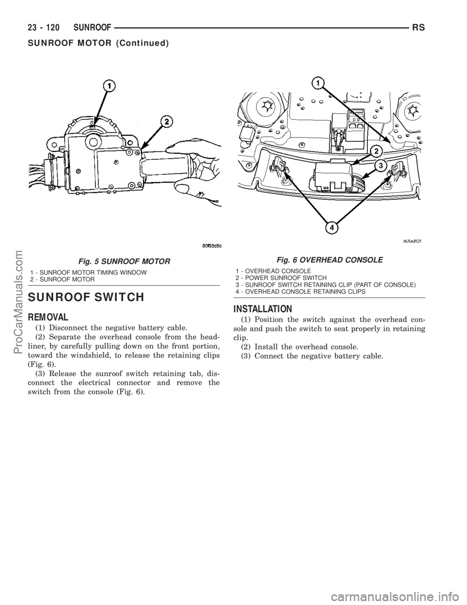
SUNROOF SWITCH
REMOVAL
(1) Disconnect the negative battery cable.
(2) Separate the overhead console from the head-
liner, by carefully pulling down on the front portion,
toward the windshield, to release the retaining clips
(Fig. 6).
(3) Release the sunroof switch retaining tab, dis-
connect the electrical connector and remove the
switch from the console (Fig. 6).
INSTALLATION
(1) Position the switch against the overhead con-
sole and push the switch to seat properly in retaining
clip.
(2) Install the overhead console.
(3) Connect the negative battery cable.
Fig. 5 SUNROOF MOTOR
1 - SUNROOF MOTOR TIMING WINDOW
2 - SUNROOF MOTOR
Fig. 6 OVERHEAD CONSOLE
1 - OVERHEAD CONSOLE
2 - POWER SUNROOF SWITCH
3 - SUNROOF SWITCH RETAINING CLIP (PART OF CONSOLE)
4 - OVERHEAD CONSOLE RETAINING CLIPS
23 - 120 SUNROOFRS
SUNROOF MOTOR (Continued)
ProCarManuals.com
Page 1856 of 2177
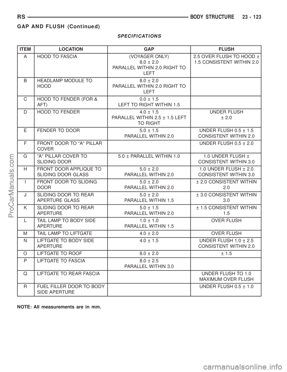
SPECIFICATIONS
ITEM LOCATION GAP FLUSH
A HOOD TO FASCIA (VOYAGER ONLY)
8.0 2.0
PARALLEL WITHIN 2.0 RIGHT TO
LEFT2.5 OVER FLUSH TO HOOD
1.5 CONSISTENT WITHIN 2.0
B HEADLAMP MODULE TO
HOOD8.0 2.0
PARALLEL WITHIN 2.0 RIGHT TO
LEFT
C HOOD TO FENDER (FOR &
AFT)0.0 1.5
LEFT TO RIGHT WITHIN 1.5
D HOOD TO FENDER 4.0 1.5
PARALLEL WITHIN 2.5 1.5 LEFT
TO RIGHTUNDER FLUSH
2.0
E FENDER TO DOOR 5.0 1.5
PARALLEL WITHIN 2.0UNDER FLUSH 0.5 1.5
CONSISTENT WITHIN 2.0
F FRONT DOOR TO9A9PILLAR
COVERUNDER FLUSH 0.5 2.0
G9A9PILLAR COVER TO
SLIDING DOOR5.0 PARALLEL WITHIN 1.0 1.0 UNDER FLUSH
CONSISTENT WITHIN 3.0
H FRONT DOOR APPLIQUE TO
SLIDING DOOR GLASS5.0 2.0
PARALLEL WITHIN 2.01.0 UNDER FLUSH 2.0
CONSISTENT WITHIN 3.0
I FRONT DOOR TO SLIDING
DOOR5.0 2.0
PARALLEL WITHIN 2.0 2.0 CONSISTENT WITHIN
2.0
J SLIDING DOOR TO REAR
APERTURE GLASS5.0 2.0
PARALLEL WITHIN 1.5 3.0 CONSISTENT WITHIN
3.0
K SLIDING DOOR TO REAR
APERTURE5.0 1.5
PARALLEL WITHIN 2.0 1.5 CONSISTENT WITHIN
1.5
L TAIL LAMP TO BODY SIDE
APERTURE1.0 1.0
PARALLEL WITHIN 1.5OVER FLUSH
M TAIL LAMP TO LIFTGATE 4.0 2.0 OVER FLUSH
N LIFTGATE TO BODY SIDE
APERTURE4.0 1.5 UNDER FLUSH 1.0 2.5
CONSISTENT WITHIN 2.0
O LIFTGATE TO ROOF 8.0 2.0 1.5
P LIFTGATE TO FASCIA 8.0 2.5
PARALLEL WITHIN 3.0
Q LIFTGATE TO REAR FASCIA UNDER FLUSH TO 1.0
MAXIMUM OVER FLUSH
R FUEL FILLER DOOR TO BODY
SIDE APERTUREUNDER FLUSH 0.5 1.0
NOTE: All measurements are in mm.
RSBODY STRUCTURE23 - 123
GAP AND FLUSH (Continued)
ProCarManuals.com
Page 1860 of 2177
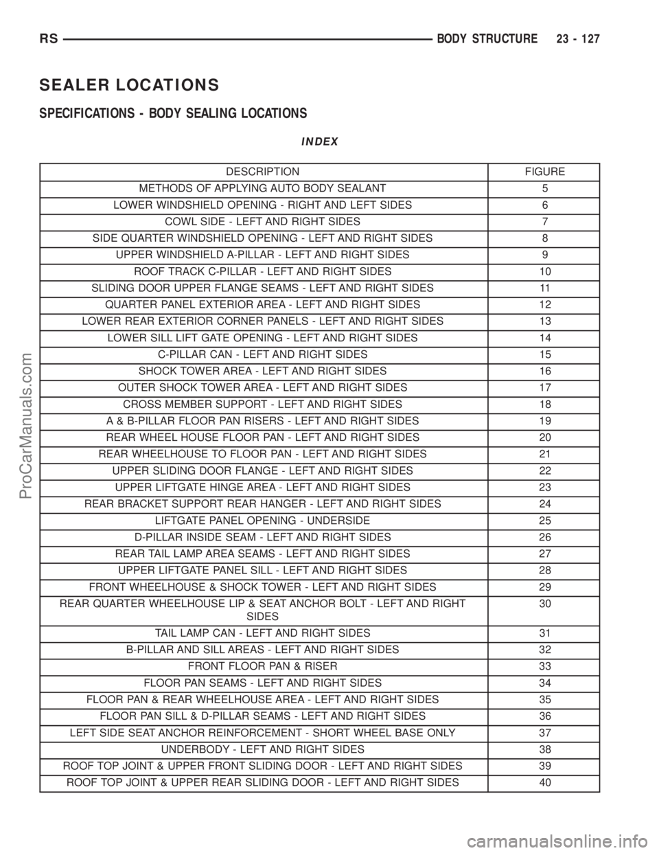
SEALER LOCATIONS
SPECIFICATIONS - BODY SEALING LOCATIONS
INDEX
DESCRIPTION FIGURE
METHODS OF APPLYING AUTO BODY SEALANT 5
LOWER WINDSHIELD OPENING - RIGHT AND LEFT SIDES 6
COWL SIDE - LEFT AND RIGHT SIDES 7
SIDE QUARTER WINDSHIELD OPENING - LEFT AND RIGHT SIDES 8
UPPER WINDSHIELD A-PILLAR - LEFT AND RIGHT SIDES 9
ROOF TRACK C-PILLAR - LEFT AND RIGHT SIDES 10
SLIDING DOOR UPPER FLANGE SEAMS - LEFT AND RIGHT SIDES 11
QUARTER PANEL EXTERIOR AREA - LEFT AND RIGHT SIDES 12
LOWER REAR EXTERIOR CORNER PANELS - LEFT AND RIGHT SIDES 13
LOWER SILL LIFT GATE OPENING - LEFT AND RIGHT SIDES 14
C-PILLAR CAN - LEFT AND RIGHT SIDES 15
SHOCK TOWER AREA - LEFT AND RIGHT SIDES 16
OUTER SHOCK TOWER AREA - LEFT AND RIGHT SIDES 17
CROSS MEMBER SUPPORT - LEFT AND RIGHT SIDES 18
A & B-PILLAR FLOOR PAN RISERS - LEFT AND RIGHT SIDES 19
REAR WHEEL HOUSE FLOOR PAN - LEFT AND RIGHT SIDES 20
REAR WHEELHOUSE TO FLOOR PAN - LEFT AND RIGHT SIDES 21
UPPER SLIDING DOOR FLANGE - LEFT AND RIGHT SIDES 22
UPPER LIFTGATE HINGE AREA - LEFT AND RIGHT SIDES 23
REAR BRACKET SUPPORT REAR HANGER - LEFT AND RIGHT SIDES 24
LIFTGATE PANEL OPENING - UNDERSIDE 25
D-PILLAR INSIDE SEAM - LEFT AND RIGHT SIDES 26
REAR TAIL LAMP AREA SEAMS - LEFT AND RIGHT SIDES 27
UPPER LIFTGATE PANEL SILL - LEFT AND RIGHT SIDES 28
FRONT WHEELHOUSE & SHOCK TOWER - LEFT AND RIGHT SIDES 29
REAR QUARTER WHEELHOUSE LIP & SEAT ANCHOR BOLT - LEFT AND RIGHT
SIDES30
TAIL LAMP CAN - LEFT AND RIGHT SIDES 31
B-PILLAR AND SILL AREAS - LEFT AND RIGHT SIDES 32
FRONT FLOOR PAN & RISER 33
FLOOR PAN SEAMS - LEFT AND RIGHT SIDES 34
FLOOR PAN & REAR WHEELHOUSE AREA - LEFT AND RIGHT SIDES 35
FLOOR PAN SILL & D-PILLAR SEAMS - LEFT AND RIGHT SIDES 36
LEFT SIDE SEAT ANCHOR REINFORCEMENT - SHORT WHEEL BASE ONLY 37
UNDERBODY - LEFT AND RIGHT SIDES 38
ROOF TOP JOINT & UPPER FRONT SLIDING DOOR - LEFT AND RIGHT SIDES 39
ROOF TOP JOINT & UPPER REAR SLIDING DOOR - LEFT AND RIGHT SIDES 40
RSBODY STRUCTURE23 - 127
ProCarManuals.com