2003 CHRYSLER CARAVAN instrument cluster
[x] Cancel search: instrument clusterPage 1320 of 2177
(7) Lower vehicle and install oil dipstick.
(8) Connect negative cable to battery.
(9) Fill crankcase with oil to proper level.
OIL PRESSURE RELIEF VALVE
REMOVAL
(1) Remove oil pan (Refer to 9 - ENGINE/LUBRI-
CATION/OIL PAN - REMOVAL).
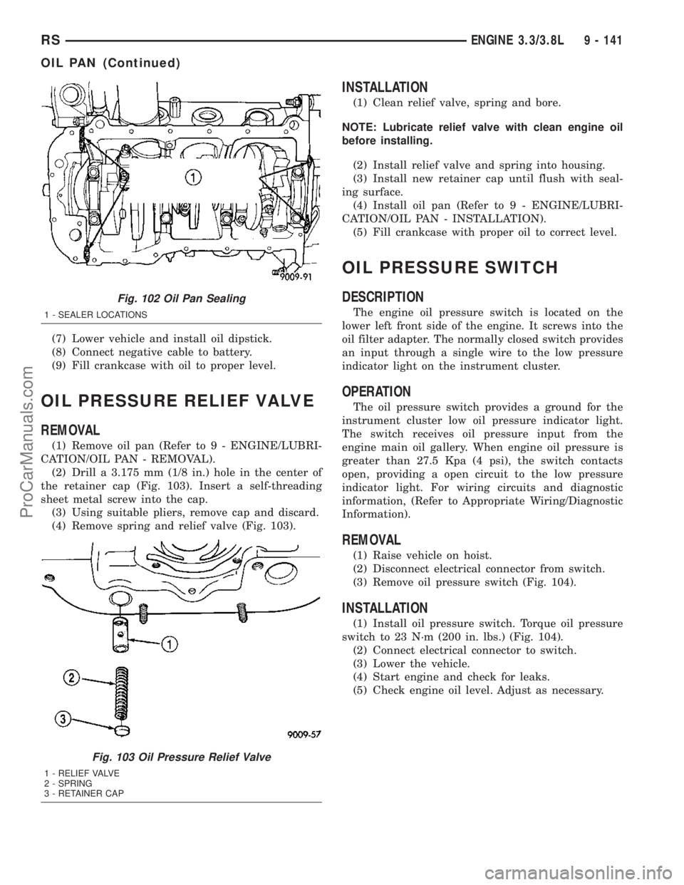
(2) Drill a 3.175 mm (1/8 in.) hole in the center of
the retainer cap (Fig. 103). Insert a self-threading
sheet metal screw into the cap.
(3) Using suitable pliers, remove cap and discard.
(4) Remove spring and relief valve (Fig. 103).
INSTALLATION
(1) Clean relief valve, spring and bore.
NOTE: Lubricate relief valve with clean engine oil
before installing.
(2) Install relief valve and spring into housing.
(3) Install new retainer cap until flush with seal-
ing surface.
(4) Install oil pan (Refer to 9 - ENGINE/LUBRI-
CATION/OIL PAN - INSTALLATION).
(5) Fill crankcase with proper oil to correct level.
OIL PRESSURE SWITCH
DESCRIPTION
The engine oil pressure switch is located on the
lower left front side of the engine. It screws into the
oil filter adapter. The normally closed switch provides
an input through a single wire to the low pressure
indicator light on the instrument cluster.
OPERATION
The oil pressure switch provides a ground for the
instrument cluster low oil pressure indicator light.
The switch receives oil pressure input from the
engine main oil gallery. When engine oil pressure is
greater than 27.5 Kpa (4 psi), the switch contacts
open, providing a open circuit to the low pressure
indicator light. For wiring circuits and diagnostic
information, (Refer to Appropriate Wiring/Diagnostic
Information).
REMOVAL
(1) Raise vehicle on hoist.
(2) Disconnect electrical connector from switch.
(3) Remove oil pressure switch (Fig. 104).
INSTALLATION
(1) Install oil pressure switch. Torque oil pressure
switch to 23 N´m (200 in. lbs.) (Fig. 104).
(2) Connect electrical connector to switch.
(3) Lower the vehicle.
(4) Start engine and check for leaks.
(5) Check engine oil level. Adjust as necessary.
Fig. 102 Oil Pan Sealing
1 - SEALER LOCATIONS
Fig. 103 Oil Pressure Relief Valve
1 - RELIEF VALVE
2 - SPRING
3 - RETAINER CAP
RSENGINE 3.3/3.8L9 - 141
OIL PAN (Continued)
ProCarManuals.com
Page 1407 of 2177
WARNING: THE AIR BAG SYSTEM IS A SENSITIVE,
COMPLEX ELECTRO-MECHANICAL UNIT. BEFORE
ATTEMPTING TO DIAGNOSE, REMOVE OR INSTALL
THE AIR BAG SYSTEM COMPONENTS YOU MUST
FIRST DISCONNECT AND ISOLATE THE BATTERY
NEGATIVE (GROUND) CABLE. THEN WAIT TWO
MINUTES FOR THE SYSTEM CAPACITOR TO DIS-
CHARGE. FAILURE TO DO SO COULD RESULT IN
ACCIDENTAL DEPLOYMENT OF THE AIR BAG AND
POSSIBLE PERSONAL INJURY. THE FASTENERS,
SCREWS, AND BOLTS, ORIGINALLY USED FOR
THE AIR BAG COMPONENTS, HAVE SPECIAL
COATINGS AND ARE SPECIFICALLY DESIGNED
FOR THE AIR BAG SYSTEM. THEY MUST NEVER
BE REPLACED WITH ANY SUBSTITUTES. ANYTIME
A NEW FASTENER IS NEEDED, REPLACE WITH
THE CORRECT FASTENERS PROVIDED IN THE
SERVICE PACKAGE OR FASTENERS LISTED IN
THE PARTS BOOKS.
WARNING: SAFETY GOGGLES SHOULD BE WORN
AT ALL TIMES WHEN WORKING ON STEERING
COLUMNS.
CAUTION: Disconnect negative (ground) cable from
the battery before servicing any column compo-
nent.
CAUTION: Do not attempt to remove the pivot pins
to disassemble the tilting mechanism. Damage will
occur.
DIAGNOSIS AND TESTING - STEERING
COLUMN
For diagnosis of conditions relating to the steering
column (Refer to 19 - STEERING - DIAGNOSIS AND
TESTING) and (Refer to 19 - STEERING - DIAGNO-
SIS AND TESTING).
REMOVAL
NOTE: Before proceeding, (Refer to 19 - STEERING/
COLUMN - WARNING).
(1) Make sure the front wheels of the vehicle are
in the STRAIGHT AHEAD position before beginning
the column removal procedure.
(2) Disconnect negative (ground) cable from the
battery and isolate cable from battery terminal.
(3) Remove the lower shroud (Refer to 19 -
STEERING/COLUMN/LOWER SHROUD - REMOV-
AL).
(4) Remove the traction off switch.
(5) Remove the upper shroud.
(6) Remove the cluster trim bezel (Refer to 23 -
BODY/INSTRUMENT PANEL/CLUSTER BEZEL -
REMOVAL).
(7) Remove the knee blocker (Refer to 23 - BODY/
INSTRUMENT PANEL/STEERING COLUMN
OPENING COVER - REMOVAL).
(8) Remove the parking brake handle link.
(9) Remove the knee blocker reinforcement (Refer
to 23 - BODY/INSTRUMENT PANEL/KNEE
BLOCKER - REMOVAL).
(10) Remove the airbag (Refer to 8 - ELECTRI-
CAL/RESTRAINTS/DRIVER AIRBAG - REMOVAL).
(11) Remove the steering wheel retaining nut.
(12) Remove the vibration damper weight.
(13) Remove the steering wheel (Refer to 19 -
STEERING/COLUMN/STEERING WHEEL -
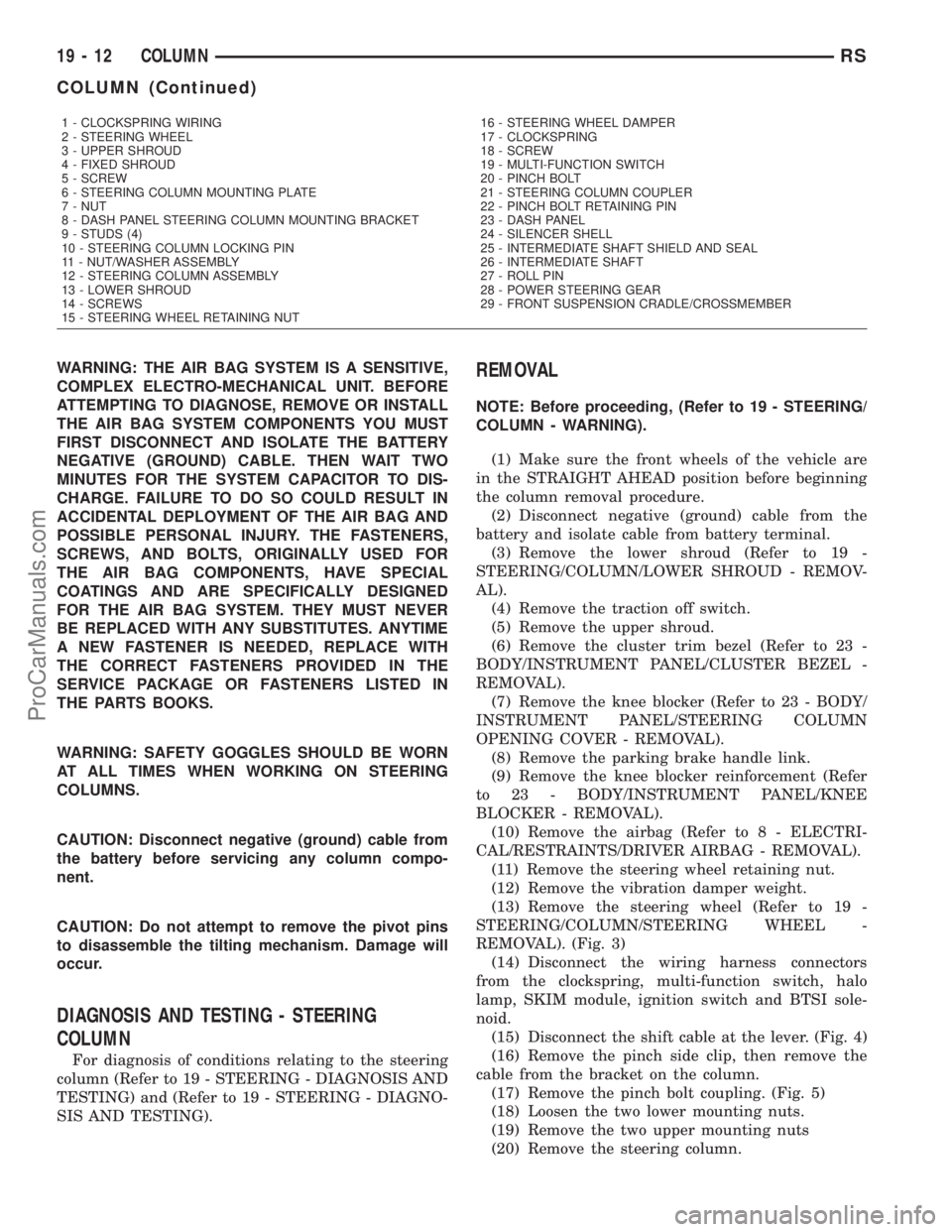
REMOVAL). (Fig. 3)
(14) Disconnect the wiring harness connectors
from the clockspring, multi-function switch, halo
lamp, SKIM module, ignition switch and BTSI sole-
noid.
(15) Disconnect the shift cable at the lever. (Fig. 4)
(16) Remove the pinch side clip, then remove the
cable from the bracket on the column.
(17) Remove the pinch bolt coupling. (Fig. 5)
(18) Loosen the two lower mounting nuts.
(19) Remove the two upper mounting nuts
(20) Remove the steering column.
1 - CLOCKSPRING WIRING
2 - STEERING WHEEL
3 - UPPER SHROUD
4 - FIXED SHROUD
5 - SCREW
6 - STEERING COLUMN MOUNTING PLATE
7 - NUT
8 - DASH PANEL STEERING COLUMN MOUNTING BRACKET
9 - STUDS (4)
10 - STEERING COLUMN LOCKING PIN
11 - NUT/WASHER ASSEMBLY
12 - STEERING COLUMN ASSEMBLY
13 - LOWER SHROUD
14 - SCREWS
15 - STEERING WHEEL RETAINING NUT16 - STEERING WHEEL DAMPER
17 - CLOCKSPRING
18 - SCREW
19 - MULTI-FUNCTION SWITCH
20 - PINCH BOLT
21 - STEERING COLUMN COUPLER
22 - PINCH BOLT RETAINING PIN
23 - DASH PANEL
24 - SILENCER SHELL
25 - INTERMEDIATE SHAFT SHIELD AND SEAL
26 - INTERMEDIATE SHAFT
27 - ROLL PIN
28 - POWER STEERING GEAR
29 - FRONT SUSPENSION CRADLE/CROSSMEMBER
19 - 12 COLUMNRS
COLUMN (Continued)
ProCarManuals.com
Page 1409 of 2177
(10) Install the coupling onto the intermediate
shaft and install the pinch bolt. Tighten the pinch
bolt to 28 N´m (250 in. lbs.).
(11) Install the cable from the bracket on the col-
umn, then install the pinch side clips.
(12) Reconnect the shift cable at the lever.
(13) Reconnect the wiring harness connectors to
the clockspring, multi-function switch, halo lamp,
SKIM module, ignition switch and BTSI solenoid.
(14) Install the steering wheel (Refer to 19 -
STEERING/COLUMN/STEERING WHEEL -
INSTALLATION).
(15) Install the vibration damper weight.
(16) Install the steering wheel retaining nut.
Tighten the nut to 61 N´m (45 ft. lbs.)
(17) Install the airbag (Refer to 8 - ELECTRICAL/
RESTRAINTS/DRIVER AIRBAG - INSTALLATION).
(18) Install the knee blocker reinforcement (Refer
to 23 - BODY/INSTRUMENT PANEL/KNEE
BLOCKER - INSTALLATION).
(19) Install the parking brake handle link.
(20) Install the knee blocker (Refer to 23 - BODY/
INSTRUMENT PANEL/STEERING COLUMN
OPENING COVER - INSTALLATION).
(21) Install the cluster trim bezel (Refer to 23 -
BODY/INSTRUMENT PANEL/CLUSTER BEZEL -
INSTALLATION).
(22) Install the upper shroud (Refer to 19 -
STEERING/COLUMN/LOWER SHROUD - INSTAL-
LATION).
(23) Install the traction off switch.
(24) Install the lower shroud.
SPECIFICATIONS
COLUMN TORQUE
DESCRIPTION N´mFt.
Lbs.In.
Lbs.
Driver Airbag Attaching Bolts 10 Ð 90
Steering Column Coupling
Pinch Bolt28 Ð 250
Steering Column Mounting
Nuts12 Ð 105
Steering Wheel Retaining
Nut61 45 Ð
IGNITION SWITCH
REMOVAL
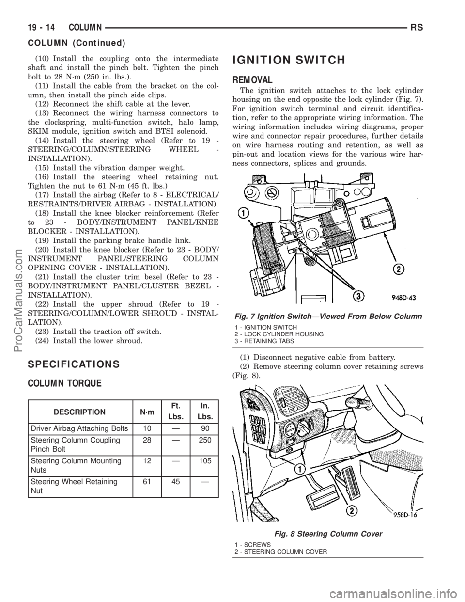
The ignition switch attaches to the lock cylinder
housing on the end opposite the lock cylinder (Fig. 7).
For ignition switch terminal and circuit identifica-
tion, refer to the appropriate wiring information. The
wiring information includes wiring diagrams, proper
wire and connector repair procedures, further details
on wire harness routing and retention, as well as
pin-out and location views for the various wire har-
ness connectors, splices and grounds.
(1) Disconnect negative cable from battery.
(2) Remove steering column cover retaining screws
(Fig. 8).
Fig. 7 Ignition SwitchÐViewed From Below Column
1 - IGNITION SWITCH
2 - LOCK CYLINDER HOUSING
3 - RETAINING TABS
Fig. 8 Steering Column Cover
1 - SCREWS
2 - STEERING COLUMN COVER
19 - 14 COLUMNRS
COLUMN (Continued)
ProCarManuals.com
Page 1412 of 2177
LOCK CYLINDER HOUSING
DESCRIPTION - IGNITION INTERLOCK
All vehicles equipped with automatic transaxles
have an interlock system. The system prevents shift-
ing the vehicle out of Park unless the ignition lock
cylinder is in the Unlock, Run or Start position. In
addition, the operator cannot rotate the key to the
lock position unless the shifter is in the park posi-
tion. On vehicles equipped with floor shift refer to
the - Transaxle for Automatic Transmission Shifter/
Ignition Interlock.
REMOVAL
NOTE: Before proceeding, review all Steering Col-
umn and Airbag Warnings and Cautions. (Refer to
19 - STEERING/COLUMN - WARNING)(Refer to 8 -
ELECTRICAL/RESTRAINTS - WARNING)
(1) Remove battery ground cable terminal from
battery negative post and isolate.
(2) Under instrument panel, remove silencer panel
below lower steering column cover.
(3) Remove screws securing lower steering column
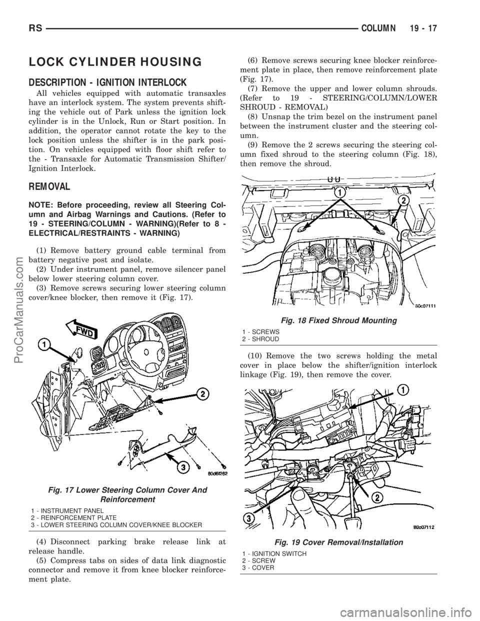
cover/knee blocker, then remove it (Fig. 17).
(4) Disconnect parking brake release link at
release handle.
(5) Compress tabs on sides of data link diagnostic
connector and remove it from knee blocker reinforce-
ment plate.(6) Remove screws securing knee blocker reinforce-
ment plate in place, then remove reinforcement plate
(Fig. 17).
(7) Remove the upper and lower column shrouds.
(Refer to 19 - STEERING/COLUMN/LOWER
SHROUD - REMOVAL)
(8) Unsnap the trim bezel on the instrument panel
between the instrument cluster and the steering col-
umn.
(9) Remove the 2 screws securing the steering col-
umn fixed shroud to the steering column (Fig. 18),
then remove the shroud.
(10) Remove the two screws holding the metal
cover in place below the shifter/ignition interlock
linkage (Fig. 19), then remove the cover.
Fig. 17 Lower Steering Column Cover And
Reinforcement
1 - INSTRUMENT PANEL
2 - REINFORCEMENT PLATE
3 - LOWER STEERING COLUMN COVER/KNEE BLOCKER
Fig. 18 Fixed Shroud Mounting
1 - SCREWS
2 - SHROUD
Fig. 19 Cover Removal/Installation
1 - IGNITION SWITCH
2 - SCREW
3 - COVER
RSCOLUMN19-17
ProCarManuals.com
Page 1416 of 2177
GEAR SHIFT LEVER
REMOVAL
(1) Remove the knee blocker (Refer to 23 - BODY/
INSTRUMENT PANEL/STEERING COLUMN
OPENING COVER - REMOVAL).
(2) Remove the knee blocker reinforcement (Refer
to 23 - BODY/INSTRUMENT PANEL/KNEE
BLOCKER - REMOVAL).
(3) Remove the upper and lower shrouds (Refer to
19 - STEERING/COLUMN/LOWER SHROUD -
REMOVAL).
(4) Remove the cluster trim bezel (Refer to 23 -
BODY/INSTRUMENT PANEL/CLUSTER BEZEL -
REMOVAL).
(5) Remove the fixed shroud from the column.
(6) Disconnect the electrical connector to the BTSI.
(7) Remove the two screws securing the BTSI to
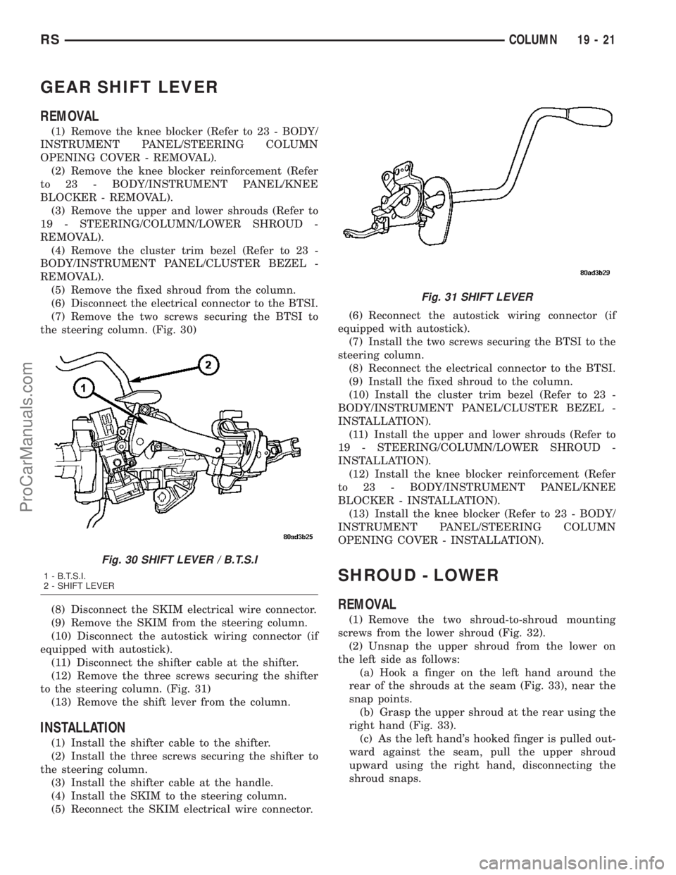
the steering column. (Fig. 30)
(8) Disconnect the SKIM electrical wire connector.
(9) Remove the SKIM from the steering column.
(10) Disconnect the autostick wiring connector (if
equipped with autostick).
(11) Disconnect the shifter cable at the shifter.
(12) Remove the three screws securing the shifter
to the steering column. (Fig. 31)
(13) Remove the shift lever from the column.
INSTALLATION
(1) Install the shifter cable to the shifter.
(2) Install the three screws securing the shifter to
the steering column.
(3) Install the shifter cable at the handle.
(4) Install the SKIM to the steering column.
(5) Reconnect the SKIM electrical wire connector.(6) Reconnect the autostick wiring connector (if
equipped with autostick).
(7) Install the two screws securing the BTSI to the
steering column.
(8) Reconnect the electrical connector to the BTSI.
(9) Install the fixed shroud to the column.
(10) Install the cluster trim bezel (Refer to 23 -
BODY/INSTRUMENT PANEL/CLUSTER BEZEL -
INSTALLATION).
(11) Install the upper and lower shrouds (Refer to
19 - STEERING/COLUMN/LOWER SHROUD -
INSTALLATION).
(12) Install the knee blocker reinforcement (Refer
to 23 - BODY/INSTRUMENT PANEL/KNEE
BLOCKER - INSTALLATION).
(13) Install the knee blocker (Refer to 23 - BODY/
INSTRUMENT PANEL/STEERING COLUMN
OPENING COVER - INSTALLATION).
SHROUD - LOWER
REMOVAL
(1) Remove the two shroud-to-shroud mounting
screws from the lower shroud (Fig. 32).
(2) Unsnap the upper shroud from the lower on
the left side as follows:
(a) Hook a finger on the left hand around the
rear of the shrouds at the seam (Fig. 33), near the
snap points.
(b) Grasp the upper shroud at the rear using the
right hand (Fig. 33).
(c) As the left hand's hooked finger is pulled out-
ward against the seam, pull the upper shroud
upward using the right hand, disconnecting the
shroud snaps.
Fig. 30 SHIFT LEVER / B.T.S.I
1 - B.T.S.I.
2 - SHIFT LEVER
Fig. 31 SHIFT LEVER
RSCOLUMN19-21
ProCarManuals.com
Page 1637 of 2177
Moving the switch up causes an upshift and moving
the switch down causes a downshift. The instrument
cluster will illuminate the selected gear. The vehicle
can be launched in 1st, 2nd, or 3rd gear while in the
Autostick mode. The speed control is operable in 3rd
and 4th gear Autostick mode. Speed control will be
deactivated if the transaxle is shifted to 2nd gear.
Shifting into OD position cancels the Autostick mode,
and the transaxle resumes the OD shift schedule.
DRIVING CLUTCHES
DESCRIPTION
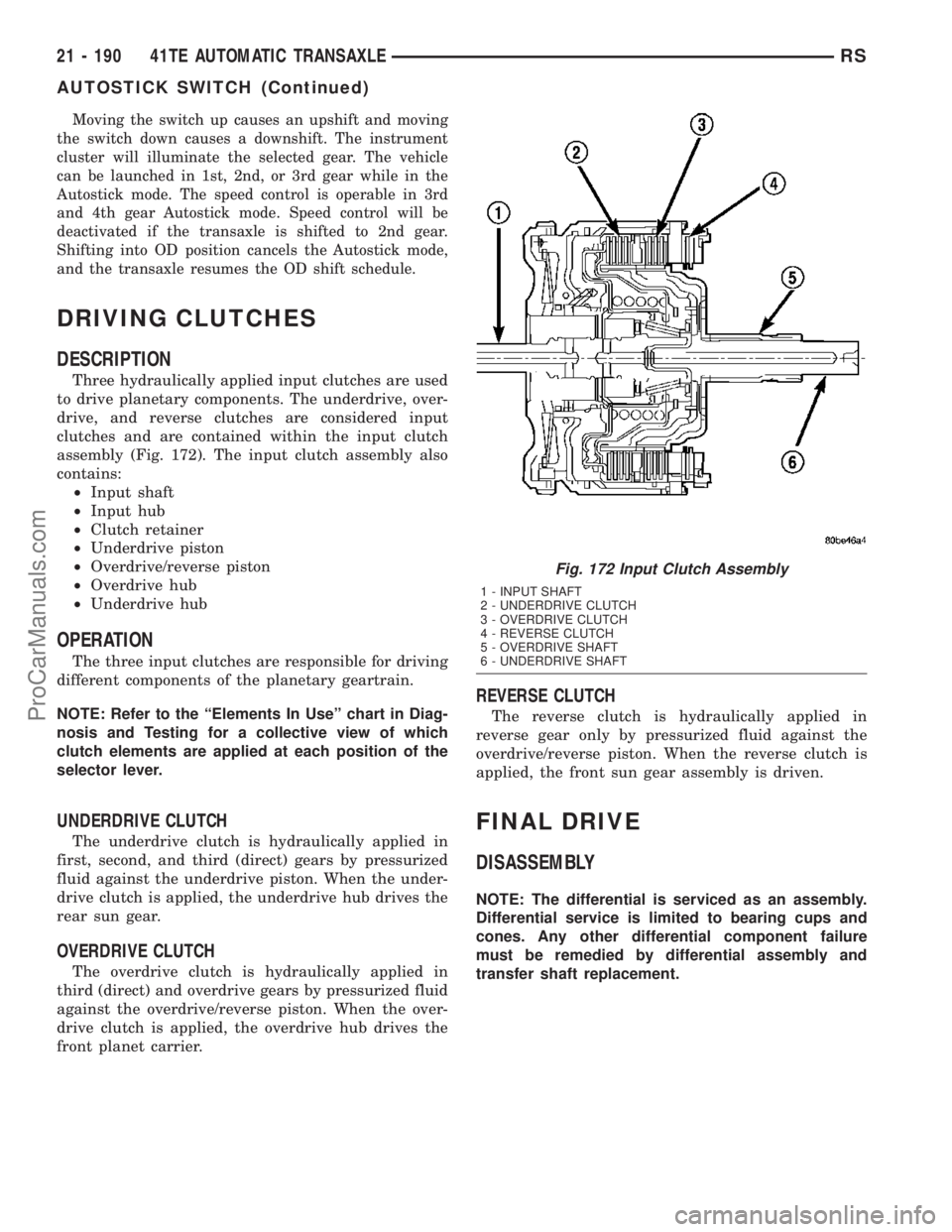
Three hydraulically applied input clutches are used
to drive planetary components. The underdrive, over-
drive, and reverse clutches are considered input
clutches and are contained within the input clutch
assembly (Fig. 172). The input clutch assembly also
contains:
²Input shaft
²Input hub
²Clutch retainer
²Underdrive piston
²Overdrive/reverse piston
²Overdrive hub
²Underdrive hub
OPERATION
The three input clutches are responsible for driving
different components of the planetary geartrain.
NOTE: Refer to the ªElements In Useº chart in Diag-
nosis and Testing for a collective view of which
clutch elements are applied at each position of the
selector lever.
UNDERDRIVE CLUTCH
The underdrive clutch is hydraulically applied in
first, second, and third (direct) gears by pressurized
fluid against the underdrive piston. When the under-
drive clutch is applied, the underdrive hub drives the
rear sun gear.
OVERDRIVE CLUTCH
The overdrive clutch is hydraulically applied in
third (direct) and overdrive gears by pressurized fluid
against the overdrive/reverse piston. When the over-
drive clutch is applied, the overdrive hub drives the
front planet carrier.
REVERSE CLUTCH
The reverse clutch is hydraulically applied in
reverse gear only by pressurized fluid against the
overdrive/reverse piston. When the reverse clutch is
applied, the front sun gear assembly is driven.
FINAL DRIVE
DISASSEMBLY
NOTE: The differential is serviced as an assembly.
Differential service is limited to bearing cups and
cones. Any other differential component failure
must be remedied by differential assembly and
transfer shaft replacement.
Fig. 172 Input Clutch Assembly
1 - INPUT SHAFT
2 - UNDERDRIVE CLUTCH
3 - OVERDRIVE CLUTCH
4 - REVERSE CLUTCH
5 - OVERDRIVE SHAFT
6 - UNDERDRIVE SHAFT
21 - 190 41TE AUTOMATIC TRANSAXLERS
AUTOSTICK SWITCH (Continued)
ProCarManuals.com
Page 1688 of 2177
SPEED SENSOR - OUTPUT
DESCRIPTION
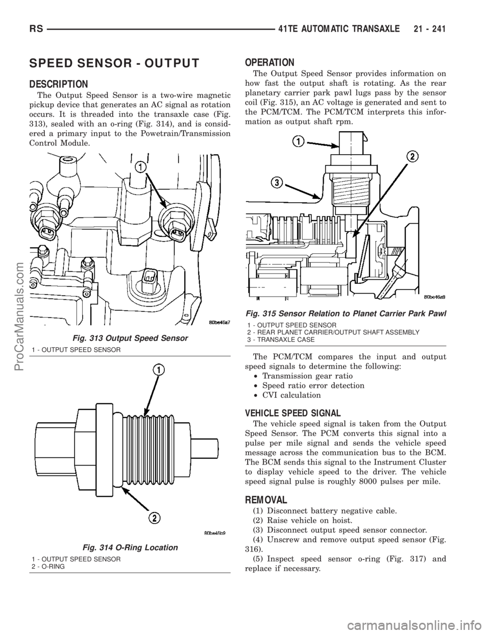
The Output Speed Sensor is a two-wire magnetic
pickup device that generates an AC signal as rotation
occurs. It is threaded into the transaxle case (Fig.
313), sealed with an o-ring (Fig. 314), and is consid-
ered a primary input to the Powetrain/Transmission
Control Module.
OPERATION
The Output Speed Sensor provides information on
how fast the output shaft is rotating. As the rear
planetary carrier park pawl lugs pass by the sensor
coil (Fig. 315), an AC voltage is generated and sent to
the PCM/TCM. The PCM/TCM interprets this infor-
mation as output shaft rpm.
The PCM/TCM compares the input and output
speed signals to determine the following:
²Transmission gear ratio
²Speed ratio error detection
²CVI calculation
VEHICLE SPEED SIGNAL
The vehicle speed signal is taken from the Output
Speed Sensor. The PCM converts this signal into a
pulse per mile signal and sends the vehicle speed
message across the communication bus to the BCM.
The BCM sends this signal to the Instrument Cluster
to display vehicle speed to the driver. The vehicle
speed signal pulse is roughly 8000 pulses per mile.
REMOVAL
(1) Disconnect battery negative cable.
(2) Raise vehicle on hoist.
(3) Disconnect output speed sensor connector.
(4) Unscrew and remove output speed sensor (Fig.
316).
(5) Inspect speed sensor o-ring (Fig. 317) and
replace if necessary.
Fig. 313 Output Speed Sensor
1 - OUTPUT SPEED SENSOR
Fig. 314 O-Ring Location
1 - OUTPUT SPEED SENSOR
2 - O-RING
Fig. 315 Sensor Relation to Planet Carrier Park Pawl
1 - OUTPUT SPEED SENSOR
2 - REAR PLANET CARRIER/OUTPUT SHAFT ASSEMBLY
3 - TRANSAXLE CASE
RS41TE AUTOMATIC TRANSAXLE21 - 241
ProCarManuals.com
Page 1795 of 2177
INSTRUMENT PANEL
TABLE OF CONTENTS
page page
CLUSTER BEZEL
REMOVAL.............................62
INSTALLATION.........................62
CUP HOLDER
REMOVAL.............................63
INSTALLATION.........................63
GLOVE BOX
REMOVAL.............................63
INSTALLATION.........................63
GLOVE BOX LATCH
REMOVAL.............................63
INSTALLATION.........................63
GLOVE BOX LATCH STRIKER
REMOVAL.............................64
INSTALLATION.........................64
INSTRUMENT PANEL ASSEMBLY
REMOVAL.............................64
INSTALLATION.........................65
INSTRUMENT PANEL CENTER BEZEL
REMOVAL.............................67
INSTALLATION.........................67
INSTRUMENT PANEL END CAP
REMOVAL.............................67INSTALLATION.........................67
INSTRUMENT PANEL TOP COVER
REMOVAL.............................67
INSTALLATION.........................67
LOWER CONSOLE
REMOVAL.............................68
INSTALLATION.........................68
LOWER INSTRUMENT PANEL
REMOVAL.............................68
INSTALLATION.........................68
LOWER STEERING COLUMN COVER
REMOVAL.............................69
INSTALLATION.........................69
STEERING COLUMN COVER BACKING PLATE
REMOVAL.............................69
INSTALLATION.........................69
OVER STEERING COLUMN COVER
REMOVAL.............................69
INSTALLATION.........................69
INSTRUMENT PANEL TOP PAD ASSEMBLY
REMOVAL.............................70
INSTALLATION.........................70
CLUSTER BEZEL
REMOVAL
(1) Disconnect and isolate the battery negative
cable.
(2) Remove Over Steering Column Bezel by lifting
it straight up with a firm pull.
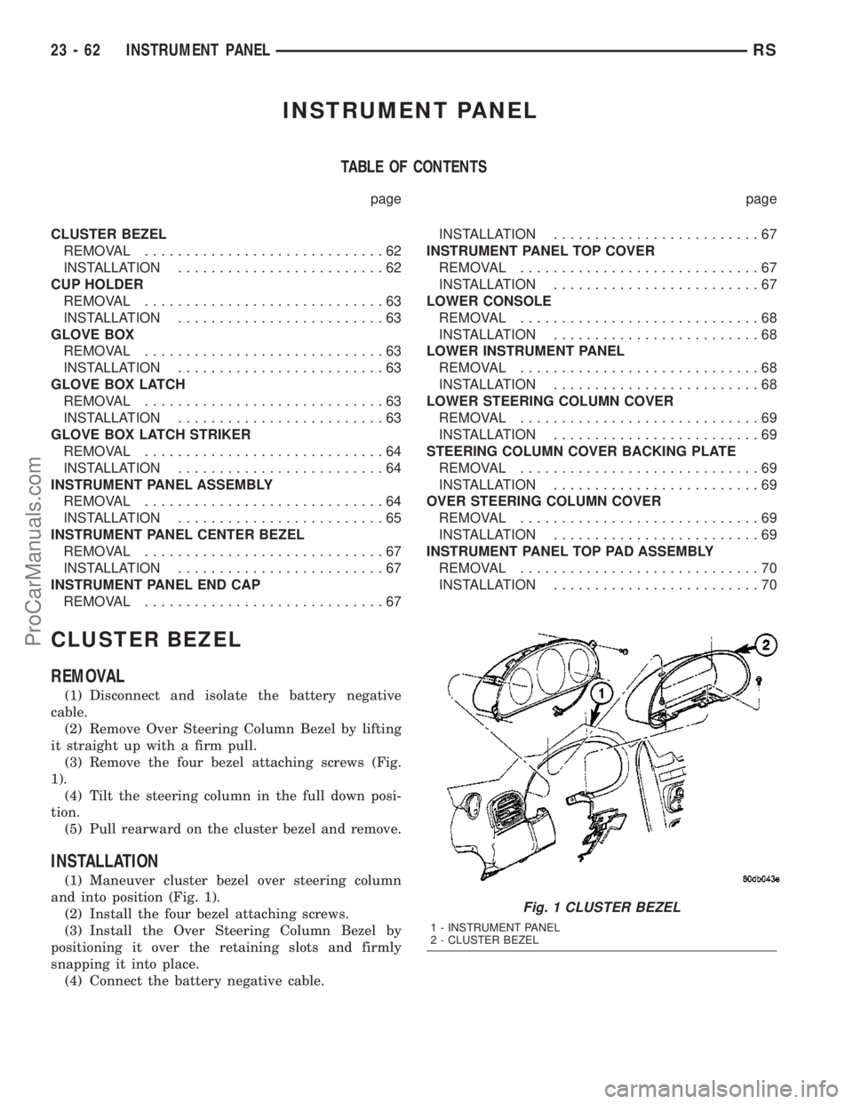
(3) Remove the four bezel attaching screws (Fig.
1).
(4) Tilt the steering column in the full down posi-
tion.
(5) Pull rearward on the cluster bezel and remove.
INSTALLATION
(1) Maneuver cluster bezel over steering column
and into position (Fig. 1).
(2) Install the four bezel attaching screws.
(3) Install the Over Steering Column Bezel by
positioning it over the retaining slots and firmly
snapping it into place.
(4) Connect the battery negative cable.
Fig. 1 CLUSTER BEZEL
1 - INSTRUMENT PANEL
2 - CLUSTER BEZEL
23 - 62 INSTRUMENT PANELRS
ProCarManuals.com